

Paper Menu >>
Journal Menu >>
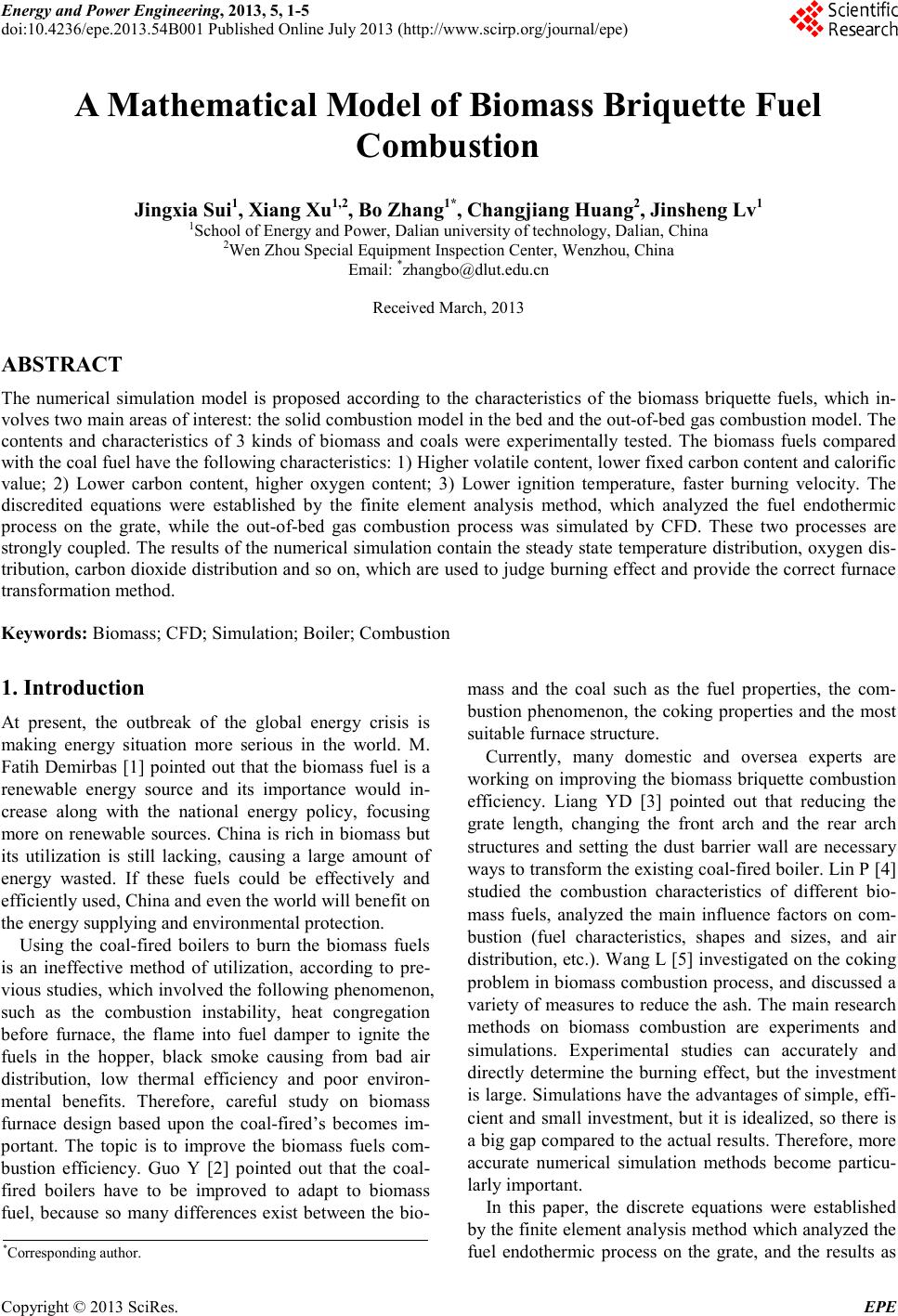 Energy and Power E ngineering, 2013, 5, 1-5 doi:10.4236/epe.2013.54B001 Published Online July 2013 (http://www.scirp .o rg/journal/epe) Copyright © 2013 SciRes. EPE A Mathematical Model of Biomass Briquette Fuel Combustion Jingxia Sui1, Xiang Xu1,2, Bo Zhang1*, Changjiang Huang2, Jinsheng Lv1 1School of Energy and Power, Dalian university of technology, Dalian, China 2Wen Zhou Speci al Equipment Inspection Center, Wenzhou, China Email: *[email protected] Received March, 2013 ABSTRACT The numerical simulation model is proposed according to the characteristics of the biomass briquette fuels, which in- volves two main areas o f i nterest: t he solid combustion mod e l in the bed and the out-of-bed gas c o mb ust ion mod el . The contents and characteristics of 3 kinds of biomass and coals were experimentally tested. The biomass fuels compared with the coal fuel have the following characteristics: 1) Higher volatile content, lower fixe d c ar bo n co nte nt and calorific value; 2) Lower carbon content, higher oxygen content; 3) Lower ignition temperature, faster burning velocity. The discredited equations were established by the finite element analysis method, which analyzed the fuel endothermic process on the grate, while the out-of-bed gas combustion process was simulated by CFD. These two processes are strongly coupled . The results of the numerical simula tion contain the stead y state temper ature distribution, oxyge n dis- tribution, carb on dioxide distr ibution and so on, which are used to judge bur ning e ffec t and p rovide the correct furnace transformat i on me th o d. Keywords: Biomass; CFD; Simulation; Boiler; Combustion 1. Introduction At present, the outbreak of the global energy crisis is making energy situation more serious in the world. M. Fatih Demirbas [1] pointed out that the biomass fuel is a renewable energy source and its importance would in- crease along with the national energy policy, focusing more on renewable sources. China is rich in bio mass but its utilization is still lacking, causing a large amount of energy wasted. If these fuels could be effectively and efficientl y used, China and even the world will benefit on the energy supplyin g and environmental prote c tio n. Using the coal-fired boilers to burn the biomass fuels is an ineffective method of utilization, according to pre- viou s studie s, whic h invol ved the follo wing phe no menon, such as the combustion instability, heat congregation before furnace, the flame into fuel damper to ignite the fuels in the hopper, black smoke causing from bad air distribution, low thermal efficiency and poor environ- mental benefits. Therefore, careful study on biomass furnace design based upon the coal-fired’s becomes im- portant. The topic is to improve the biomass fuels com- bustion efficiency. Guo Y [2] pointed out that the coal- fired boilers have to be improved to adapt to biomass fuel, because so many differences exist between the bio- mass and the coal such as the fuel properties, the com- bustion phenomenon, the coking properties and the most suitable furnace structure. Currently, many domestic and oversea experts are working on improving the biomass briquette combustion efficiency. Liang YD [3] pointed out that reducing the grate length, changing the front arch and the rear arch structures and setting the dust barrier wall are necessary way s t o transform the existing coal-fired bo iler . Li n P [4] studied the combustion characteristics of different bio- mass fuels, analyzed the main influence factors on com- bustion (fuel characteristics, shapes and sizes, and air distribution, etc.). Wan g L [5] inve sti gated o n the coking problem in bio mass c ombustio n process, and discussed a variety of measures to reduce the ash. The main research methods on biomass combustion are experiments and simulations. Experimental studies can accurately and directly determine the burning effect, but the investment is large. Simulations have the advantages of s imple, effi- cient and s mall inves tment, b ut it is idealized, so there is a big gap compared to the actual res ults. Therefore, more accurate numerical simulation methods become particu- larly importan t. In this paper, the discrete equations were established by t he fi nite e le ment ana l ysis metho d whic h anal yzed the fuel endothermic process on the grate, and the results as *Corresponding author. 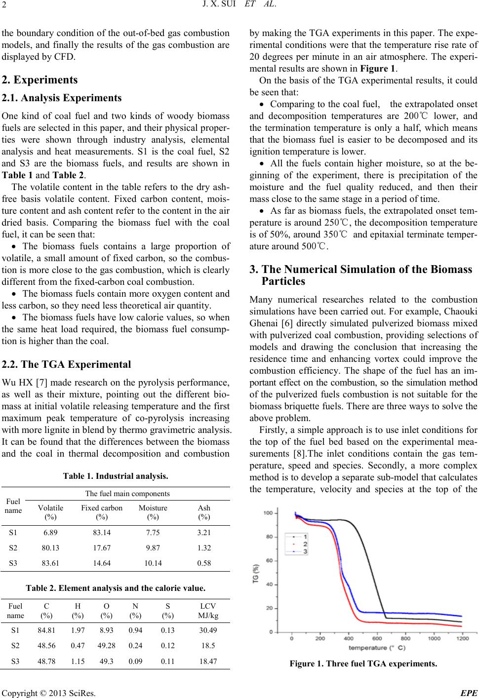 J. X. SUI ET AL. Copyright © 2013 SciRes. EPE 2 the boundary condition of the out-of-bed gas combustion models, and finally the results of the gas combustion are displayed by CFD. 2. Experiments 2.1. Analysis Experiments One kind of coal fuel and two kinds of woody biomass fuels are selected in this paper, and their physical proper- ties were shown through industry analysis, elemental analysis and heat measurements. S1 is the coal fuel, S2 and S3 are the biomass fuels, and results are shown in Table 1 and Table 2. The volatile content in the table refers to the dry ash- free basis volatile content. Fixed carbon content, mois- ture content and ash content refer to the content in the air dried basis. Comparing the biomass fuel with the coal fuel, it can be seen that: • The biomass fuels contains a large proportion of volatile, a small amount of fixed carbon, so the combus- tion is more close to the gas combustion, which is clea rl y different from the fixed-carbon coal combustion. • The b iomass fuel s co ntai n mo re oxyge n co ntent and less carbon, so they need less theoretical air quantity. • The b iomass fue ls have l ow calorie values, so when the same heat load required, the biomass fuel consump- tion i s highe r tha n the coal. 2.2. The TGA Experimental Wu HX [7] made research on the pyrolysis performance, as well as their mixture, pointing out the different bio- mass at initial volatile releasing temperature and the first maximum peak temperature of co-pyrolysis increasing with more lignite in blend by t he r mo gr avi me tr ic analysis. It can be found that the differences between the biomass and the coal in thermal decomposition and combustion Table 1. Industrial analysi s. Fuel name The fuel main components Volat ile (%) Fixed carbon (%) Moisture (%) Ash (%) S1 6.89 83.14 7.75 3.21 S2 80.13 17.67 9.87 1.32 S3 83.61 14.64 10.14 0.58 Table 2. Element analysis and the calorie value. Fuel name C (%) H (%) O (%) N (%) S (%) LCV MJ/kg S1 84.81 1.97 8.93 0.94 0.13 30.49 S2 48.56 0.47 49.28 0.24 0.12 18.5 S3 48.78 1.15 49.3 0.09 0.11 18.47 by ma king t he T GA exp er ime nts i n thi s pap er . The expe- rimental conditio ns wer e that the temperature rise rate of 20 degrees per minute in an air atmosphere. The experi- mental results are shown in Figure 1. On the basis of the TGA experimental results, it co uld be seen that: • Comparing to the coal fuel, the extrapola ted onset and decomposition temperatures are 200℃ lower, and the termination temperature is only a half, which means that the biomass fuel is easier to be decomposed and its ignition temper a ture is lower. • All the fuels contain higher moisture, so at the be- ginning of the experiment, there is precipitation of the moisture and the fuel quality reduced, and then their mass close to the same stage in a period of time. • As far as bio mass fuels, the extrapolated onset tem- perature is around 250℃, the dec omposition temper ature is of 50%, around 350℃ and ep ita xial ter minate temper- ature around 500℃. 3. The Numerical Simulation of the Biomass Particles Many numerical researches related to the combustion simulations have been carried out. For example, Chaouki Ghenai [6] directly simulated pulverized biomass mixed with pulverized coal combustion, providing select ions of models and drawing the conclusion that increasing the residence time and enhancing vortex could improve the combustion efficiency. The shape of the fuel has an im- portant effect on the combustion, so the simulation met ho d of the pulverized fuels combustion is not suitable for the biomass briquette fuels. T here are three ways to solve the above problem. Firstly, a simple approach is to use inlet conditions for the top of the fuel bed based on the experimental mea- surements [8].The inlet conditions contain the gas tem- perature, speed and species. Secondly, a more complex method is to develop a separate sub-mode l that ca lcula tes the temperature, velocity and species at the top of the Figure 1. Three fuel TGA experiments. 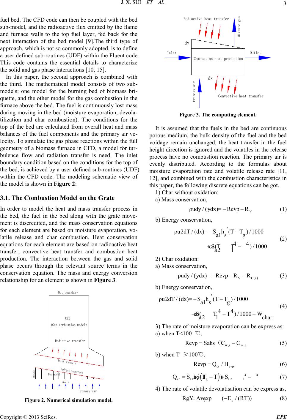 J. X. SUI ET AL. Copyright © 2013 SciRes. EPE 3 fuel bed. The CFD code can then be coupled with the bed sub-model, and the radioactive flux emi tted by the flame and furnace walls to the top fuel layer, fed back for the next interaction of the bed model [9].The third type of approach, which is not so commonly adopted, is to define a user defined sub-ro utine s (U DF) withi n the F luent cod e. This code contains the essential details to characterize the solid and gas phase interactions [10, 15]. In this paper, the second app roach is combined with the third. The mathematical model consists of two sub- models: one model for the burning bed of biomass bri- quette, and the other model for the gas co mbustion in the furnace above the bed. The fue l is continuously lost mass during moving in the bed ( moisture evaporation, devola- tilization and char combustion). The conditions for the top of the bed are calculated from overall heat and mass balances of the fuel components and the primary air ve- locity. To simulate the gas ph ase reactio ns within the full geometry of a biomass furnace in CFD, a model for tur- bulence flow and radiation transfer is need. The inlet boundary condition based on the conditions for the top of the bed, is achieved by a user defined sub-routines (UD F) within the CFD code. The modeling schematic view of the model is shown in Figure 2: 3.1. The Combustion Model on the Grate In order to model the heat and mass transfer process in the bed, the fuel in the bed along with the grate move- ment is discredited, and the mass conservation equations for each element are based on moisture evaporation, vo- latile release and char combustion. Heat conservation equations for each element are based on radioactive heat transfer, convective heat transfer and combustion heat production. The interaction between the gas and solid phase occurs through the relevant source terms in the conservation equation. The mass and energy conversion relationship for an element is shown in Figure 3. CFD Inlet boundary Grate Primary air Bed model Bed-gas interface Radiative transfer Height Out boundary (Gas combustion model) Figure 2. Numerical simulation model. Inlet Outlet dy dx Radiactive heat transfer Convective heat transfer Combustion heat production Primary air Mixture gas Figure 3. The computing element. It is assumed that the fuels in the bed are continuous porous medium, the bulk density of the fuel and the bed voidage remain unchanged; the heat transfer in the fuel height direction is i gnored and the volatiles in t he release process have no combustion reaction. The primary air is evenly distributed. According to the formulas about moisture evaporation rate and volatile release rate [11, 12], and combi ned wit h the combustion characteristics in this paper, the followin g d iscrete equations can b e got. 1) Char without oxidatio n: a) Mass conservation, V ρudy / (ydx)=RevpR−− (1) b) Energy conservatio n, ' ρu2dT / (dx)=Sh(TT) /1000 a1 sg 44 Sεσ(T T a) 2/10 0 l0 −− +− (2) 2) Char oxidatio n: a) Mass conservation, V C(s) ρudy / (ydx)=RevpRR− −− (3) b) Energy conservatio n, ' ρu2dT / (dx)=Sh(TT) /1000 a1 sg 44 Sεσ() /10T0TW a2 lchar 0 −− ++− (4) 3) The rate of moisture evaporation can be express as: a) when T<100 ℃, w,s w,g Revp Sahs CC= −() (5) b) when T ≥100℃, cr evp RevpQ/H= (6) ( ) ' 44 cra1 sga2l QSh TTSεσ(TT )= −+ − (7) 4) The rate of volatile devolati satio n can be express as, VV v RρY Avexp/(E )(RT )= − (8) 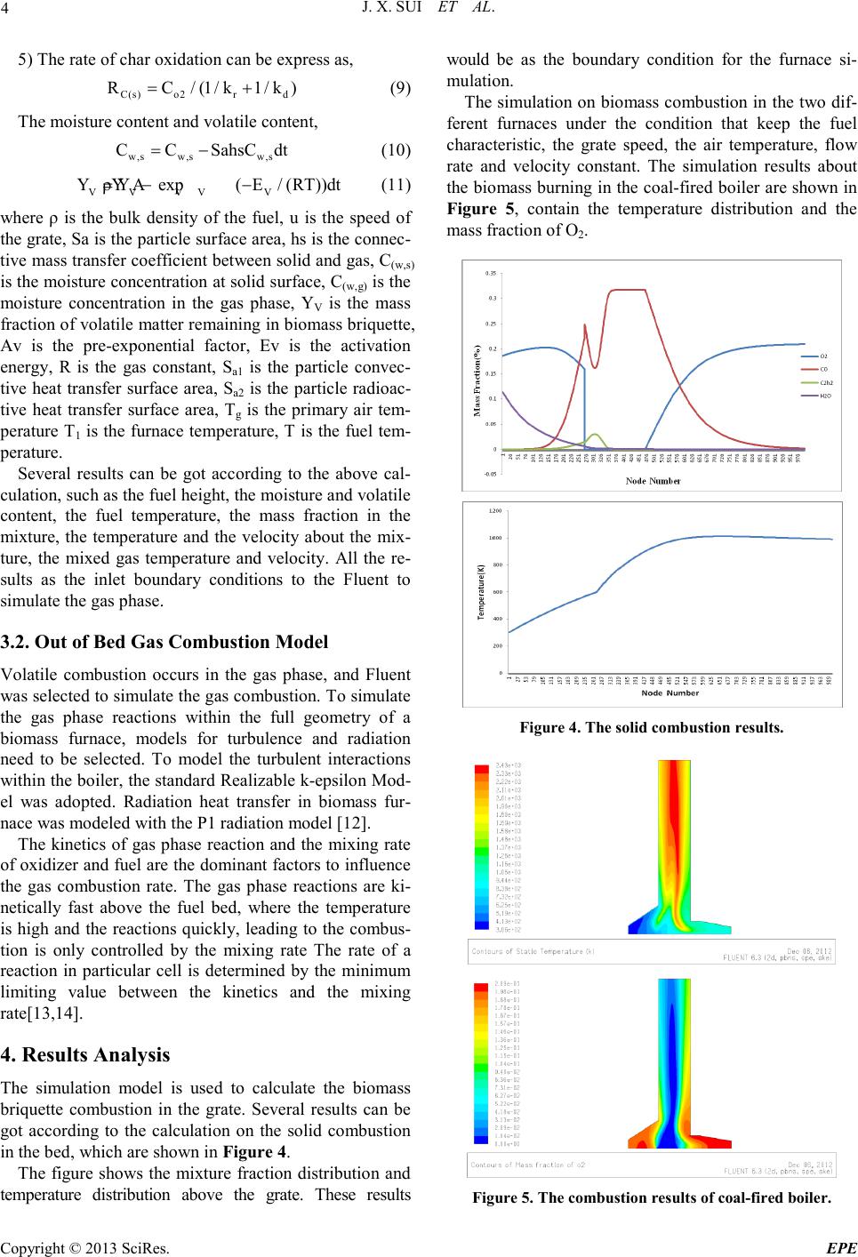 J. X. SUI ET AL. Copyright © 2013 SciRes. EPE 4 5) The rate of char oxidation can be express as, C(s) o2rd RC/(1/k1/k)= + (9) The moisture cont ent and volatile content, w,s w,sw,s CCSahsC dt= − (10) V VVVV YYρY Aexp/(( ERT))dt =−− (11) where ρ is the bulk density of the fuel, u is the speed of the grate, Sa is the particle surface area, hs is the co nnec- tive mass transfer coefficient bet ween solid and gas, C(w,s) is the moisture concentration at solid surface, C(w,g) is the moisture concentration in the gas phase, YV is the mass fraction of volati le matter remaining in biomass briquette, Av is the pre-exponential factor, Ev is the activation energy, R is the gas constant, Sa1 is the particle convec- tive heat transfer surface area, Sa2 is the particle radioac- tive heat transfer surface area, Tg is the primary air tem- perature T1 is the furnace temperature, T is the fuel tem- perature. Several results can be got according to the above cal- culat io n, such as the f ue l hei g ht, the moi s tur e a nd volat il e content, the fuel temperature, the mass fraction in the mixture, the temperature and the velocity about the mix- ture, the mixed gas temperature and velocity. All the re- sults as the inlet boundary conditions to the Fluent to simulate the gas phas e. 3.2. Out of Bed Gas Combustion Model Volatile combustion occurs in the gas phase, and Fluent was selected to simulate the gas combustion. To simulate the gas phase reactions within the full geometry of a biomass furnace, models for turbulence and radiation need to be selected. To model the turbulent interactions within the boiler, the standard Realizable k-epsilon Mod- el was adopted. Radiation heat transfer in biomass fur- nace was modeled with the P1 radiation model [12]. The kinetics of gas phase reaction and the mixing rate of oxidizer and fuel are the dominant factors to influence the gas combustion rate. The gas phase reactions are ki- netically fast above the fuel bed, where the temperature is high and the reactions quickly, leading to the combus- tion is only controlled by the mixing rate The rate of a reaction in particular cell is determined by the minimum limiting value between the kinetics and the mixing rate[13,14]. 4. Results Analysis The simulation model is used to calculate the biomass briquette combustion in the grate. Several results can be got according to the calculation on the solid combustion in the bed, which are shown in Figure 4. The figure shows t he mixture fraction distributio n and temperature distribution above the grate. These results wo u ld be as the boundary condition for the furnace si- mulation. The simulation on biomass combustion in the two dif- ferent furnaces under the condition that keep the fuel characteristic, the grate speed, the air temperature, flow rate and velocity constant. The simulation results about the bi omass b urning in the coal -fired b oiler are shown in Figure 5, contain the temperature distribution and the mass fraction of O2. Figure 4. The solid combus ti o n re sul ts. Figure 5. The combus t ion results of coal-fired boiler. 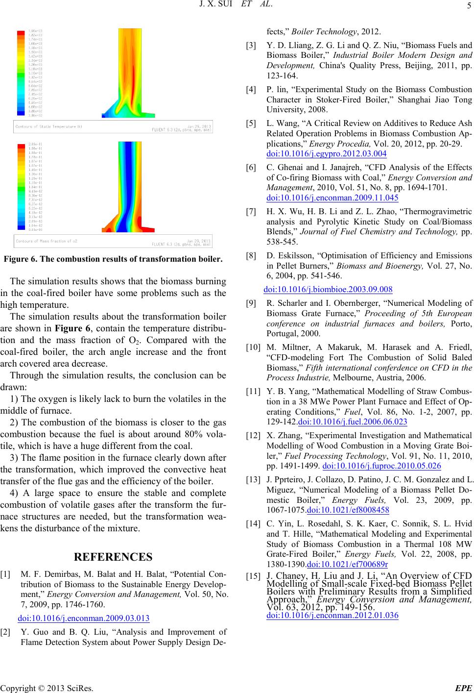 J. X. SUI ET AL. Copyright © 2013 SciRes. EPE 5 Figure 6. The combus t ion results of transformation boi ler. The simulatio n resul ts sho ws t hat the b iomass b urnin g in the coal-fired boiler have some problems such as the high temperature. The simulation results about the transformation boiler are shown in Figure 6, contain the temperature distribu- tion and the mass fraction of O2. Compared with the coal-fired boiler, the arch angle increase and the front arch covered area decrease. Through the simulation results, the conclusion can be drawn: 1) The o xyge n i s l i kely lack t o b ur n t he vo la ti le s in th e middle of furnace. 2) The combustion of the biomass is closer to the gas combustion because the fuel is about around 80% vola- tile, which is have a huge different from the coal. 3) The flame positio n in the furnace clearly down after the transformation, which improved the convective heat transfer of the flue gas and the efficienc y of the boil er. 4) A large space to ensure the stable and complete combustion of volatile gases after the transform the fur- nace structures are needed, but the transformation wea- kens t he disturbance of the mixture. REFERENCES [1] M. F. Demirbas, M. Balat and H. Balat, “Potential Con- tribution of Biomass to the Sustainable Energy Develop- ment,” Energy Conversion and Management, Vol. 50, No. 7, 2009, pp. 1746-1760. doi:10.1016/j.enconman.2009.03.013 [2] Y. Guo and B. Q. Liu, “Analysis and Improvement of Flame Detection System about Power Supply Design De- fects,” Boiler Technology, 2012. [3] Y. D. Lliang, Z. G. Li and Q. Z. Niu, “Biomass Fuels an d Biomass Boiler,” Industrial Boiler Modern Design and Development, China's Quality Press, Beijing, 2011, pp. 123-164. [4] P. lin, “Experimental Study on the Biomass Combustion Character in Stoker-Fired Boiler,” Shanghai Jiao Tong Universit y, 2008. [5] L. Wang, “A Critical Review on Additives to Reduce Ash Related Operation Problems in Biomass Combustion Ap- plications,” Energy Proced ia, Vol. 20, 2012, pp. 20-29. doi:10.1016/j.egypro.2012.03.004 [6] C. Ghenai and I. Janajreh, “CFD Analysis of the Effects of Co-firing Biomass with Coal,” Energy Conversion and Management, 2010, Vol. 51, No. 8, pp. 1694-1701. doi:10.1016/j.enconman.2009.11.045 [7] H. X. Wu, H. B. Li and Z. L. Zhao, “Thermogravimetric analysis and Pyrolytic Kinetic Study on Coal/Biomass Blends,” Journal of Fuel Chemistry and Technology, pp. 538-545. [8] D. Eskilsson, “Optimisation of Efficiency and Emissions in Pellet Burners,” Biomass and Bioenergy, Vol. 27, No. 6, 2004, pp. 541-546. doi:10.1016/j.biombioe.2003.09.008 [9] R. Scharler and I. Obernberger, “Numerical Modeling of Biomass Grate Furnace,” Proceeding of 5th European conference on industrial furnaces and boilers, Porto, Portug a l, 20 00 . [10] M. Miltner, A Makaruk, M. Harasek and A. Friedl, “CFD-modeling Fort The Combustion of Solid Baled Biomass,” Fifth international conferdence on CFD in the Process Ind ustrie, Melbourne, Austria, 2006. [11] Y. B. Yang, “Mathematical Modell ing of Straw Combus- tio n in a 38 MWe Power Plant Fur nace and Effec t of Op- erating Conditions,” Fuel, Vol. 86, No. 1-2, 2007, pp. 129-142.doi:10.1016/j.fuel.2006.06.023 [12] X. Zhang, “Experimental Investigation and Mathematical Modelling of Wood Combustion in a Moving Grate Boi- ler,” Fuel Processing Technology, Vol. 91, No. 11, 2010, pp. 1491 -1499. doi:10.1016/j.fuproc.2010.05.026 [13] J. Pprteiro, J. Collazo, D. Patino, J. C. M. Gonzalez and L. Miguez, “Numerical Modeling of a Biomass Pellet Do- mestic Boiler,” Energy Fuels, Vol. 23, 2009, pp. 1067-1075.doi:10.1021/ef8008458 [14] C. Yin, L. Rosedahl, S. K. Kaer, C. Sonnik, S. L. Hvid and T. Hille, “Mathematical Modeling and Experimental Study of Biomass Combustion in a Thermal 108 MW Grate-Fired Boiler,” Energy Fuels, Vol. 22, 2008, pp. 1380-1390.doi:10.1021/ef700689r [15] J. Chaney, H. Liu and J. Li, “An Overview of CFD Modelling of Small-scale Fixed-bed Biomass Pellet Boilers with Preliminary Results from a Simplified Approach,” Energy Conversion and Management, Vol. 63, 2012, pp. 149-156. doi:10.1016/j.enconman.2012.01.036 |