

Paper Menu >>
Journal Menu >>
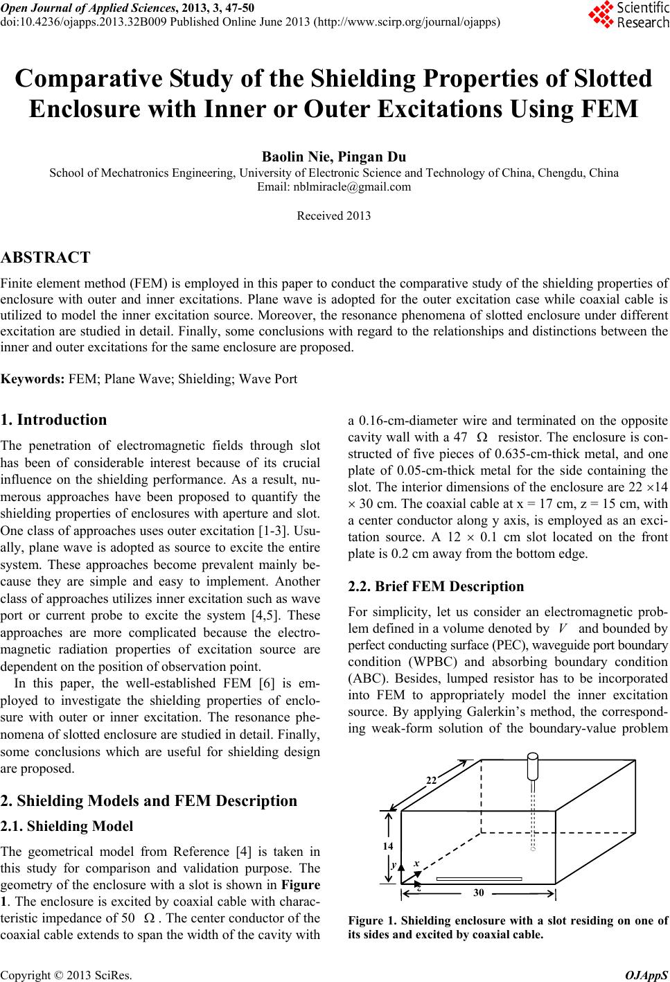 Open Journal of Applied Sciences, 2013, 3, 47-50 doi:10.4236/ojapps.2013.32B009 Published Online June 2013 (http://www.scirp.org/journal/ojapps) Comparative Study of the Shielding Properties of Slotted Enclosure with Inner or Outer Excitations Using FEM Baolin Nie, Pingan Du School of Mechatronics Engineering, University of Electronic Science and Technology of China, Chengdu, China Email: [email protected] Received 2013 ABSTRACT Finite element method (FEM) is employed in this paper to conduct the comparative study of the shielding properties of enclosure with outer and inner excitations. Plane wave is adopted for the outer excitation case while coaxial cable is utilized to model the inner excitation source. Moreover, the resonance phenomena of slotted enclosure under different excitation are studied in detail. Finally, some conclusions with regard to the relationships and distinctions between the inner and outer excitations for the same enclosure are proposed. Keywords: FEM; Plane Wave; Shielding; Wave Port 1. Introduction The penetration of electromagnetic fields through slot has been of considerable interest because of its crucial influence on the shielding performance. As a result, nu- merous approaches have been proposed to quantify the shielding properties of enclosures with aperture and slot. One class of approaches uses outer excitation [1-3]. Usu- ally, plane wave is adopted as source to excite the entire system. These approaches become prevalent mainly be- cause they are simple and easy to implement. Another class of approaches utilizes inner excitation such as wave port or current probe to excite the system [4,5]. These approaches are more complicated because the electro- magnetic radiation properties of excitation source are dependent on the position of observation point. In this paper, the well-established FEM [6] is em- ployed to investigate the shielding properties of enclo- sure with outer or inner excitation. The resonance phe- nomena of slotted enclosure are studied in detail. Finally, some conclusions which are useful for shielding design are proposed. 2. Shielding Models and FEM Description 2.1. Shielding Model The geometrical model from Reference [4] is taken in this study for comparison and validation purpose. The geometry of the enclosure with a slot is shown in Figure 1. The enclosure is excited by coaxial cable with charac- teristic impedance of 50 . The center conductor of the coaxial cable extends to span the width of the cavity with a 0.16-cm-diameter wire and terminated on the opposite cavity wall with a 47 resistor. The enclosure is con- structed of five pieces of 0.635-cm-thick metal, and one plate of 0.05-cm-thick metal for the side containing the slot. The interior dimensions of the enclosure are 22 14 30 cm. The coaxial cable at x = 17 cm, z = 15 cm, with a center conductor along y axis, is employed as an exci- tation source. A 12 0.1 cm slot located on the front plate is 0.2 cm away from the bottom edge. 2.2. Brief FEM Description For simplicity, let us consider an electromagnetic prob- lem defined in a volume denoted by and bounded by perfect conducting surface (PEC), waveguide port boundary condition (WPBC) and absorbing boundary condition (ABC). Besides, lumped resistor has to be incorporated into FEM to appropriately model the inner excitation source. By applying Galerkin’s method, the correspond- ing weak-form solution of the boundary-value problem V 22 x y z 14 30 Figure 1. Shielding enclosure with a slot residing on one of its sides and excited by coaxial cable. Copyright © 2013 SciRes. OJAppS 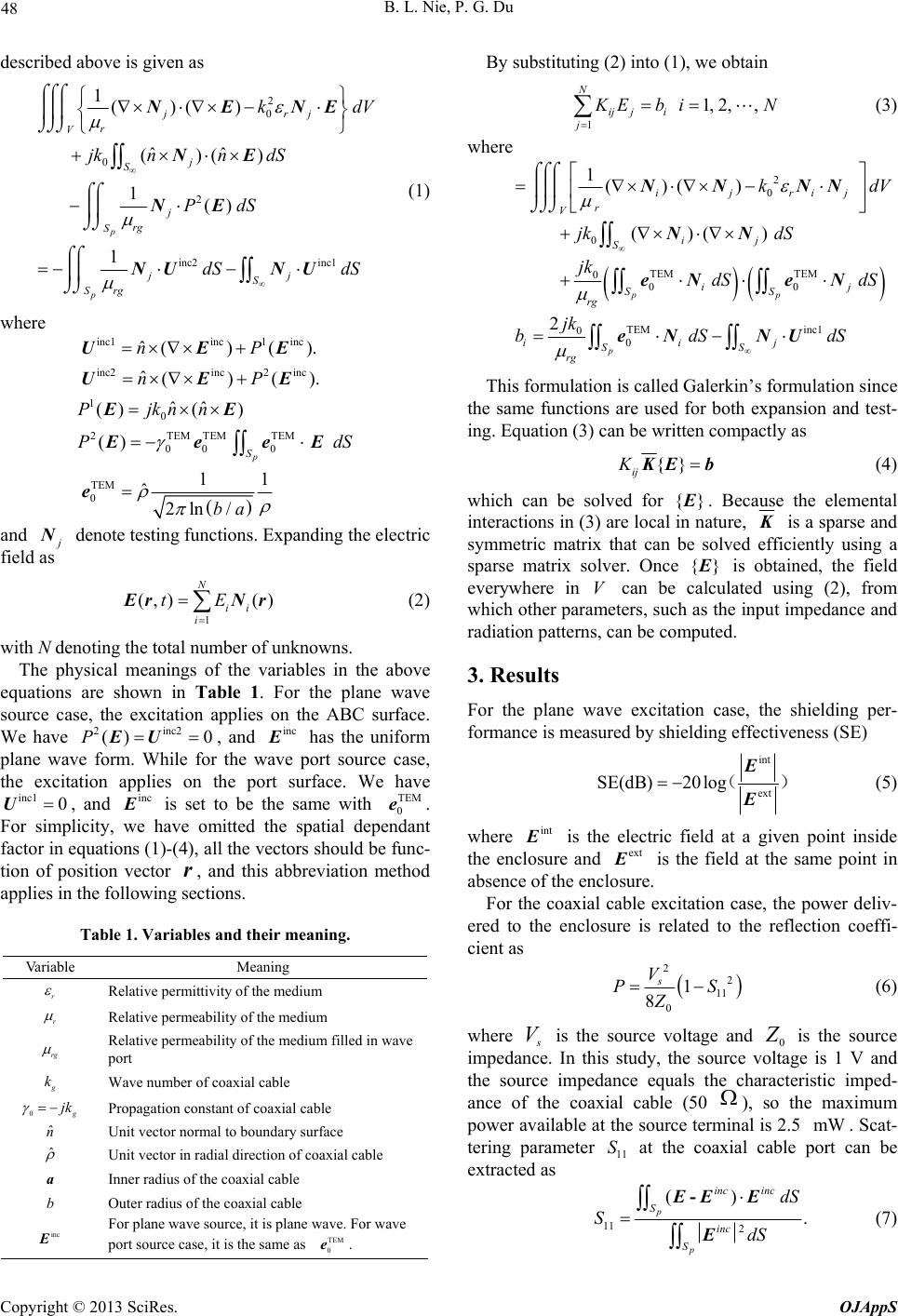 B. L. Nie, P. G. Du 48 described above is given as 2 0 0 2 inc2 inc1 1()() ˆˆ ()() 1() 1 p p jrj r V j S j rg S jj S rg S kd jknn dS PdS dS dS NENE NE NE NU NU V (1) where inc1inc1 inc inc2inc2 inc 1 0 2TEM TEMTEM 00 0 TEM 0 ˆ()(). ˆ()(). ˆˆ ()( ) () 11 ˆ 2ln / p S nP nP Pjknn P ba UEE UEE EE EeeE e d S and j N denote testing functions. Expanding the electric field as 1 (,) () N ii i tE E rNr (2) with N denoting the total number of unknowns. The physical meanings of the variables in the above equations are shown in Table 1. For the plane wave source case, the excitation applies on the ABC surface. We have , and 2inc2 () 0PE Uinc E has the uniform plane wave form. While for the wave port source case, the excitation applies on the port surface. We have , and inc1 0Uinc E is set to be the same with . For simplicity, we have omitted the spatial dependant factor in equations (1)-(4), all the vectors should be func- tion of position vector , and this abbreviation method applies in the following sections. TEM 0 e r Table 1. Variables and their meaning. Variable Meaning r Relative permittivity of the medium r Relative permeability of the medium rg Relative permeability of the medium filled in wave port g k Wave number of coaxial cable 0g jk Propagation constant of coaxial cable ˆ n Unit vector normal to boundary surface ˆ Unit vector in radial direction of coaxial cable a Inner radius of the coaxial cable b Outer radius of the coaxial cable inc E For plane wave source, it is plane wave. For wave port source case, it is the same as . TEM 0 e By substituting (2) into (1), we obtain 1 1, 2,, N ij ji j K Ebi N (3) where 2 0 0 TEM TEM 0 00 TEM inc1 0 0 1()( ) ()( ) 2 pp p ijrij r V ij S ij SS rg iij SS rg kd jk dS jk dS dS jk bdS NN NN NN eN eN eN NU V dS This formulation is called Galerkin’s formulation since the same functions are used for both expansion and test- ing. Equation (3) can be written compactly as {} ij K K Eb (4) which can be solved for {} E . Because the elemental interactions in (3) are local in nature, K is a sparse and symmetric matrix that can be solved efficiently using a sparse matrix solver. Once {} E is obtained, the field everywhere in V can be calculated using (2), from which other parameters, such as the input impedance and radiation patterns, can be computed. 3. Results For the plane wave excitation case, the shielding per- formance is measured by shielding effectiveness (SE) int ext SE(dB)20 log ( E E ) (5) where int E is the electric field at a given point inside the enclosure and ext E is the field at the same point in absence of the enclosure. For the coaxial cable excitation case, the power deliv- ered to the enclosure is related to the reflection coeffi- cient as 2 2 11 0 1 8 s V P Z S (6) where s V is the source voltage and 0 Z is the source impedance. In this study, the source voltage is 1 V and the source impedance equals the characteristic imped- ance of the coaxial cable (50 ), so the maximum power available at the source terminal is 2.5 . Scat- tering parameter at the coaxial cable port can be extracted as mW 11 S 11 2 () . p p inc inc S inc S dS SdS -EE E E (7) Copyright © 2013 SciRes. OJAppS 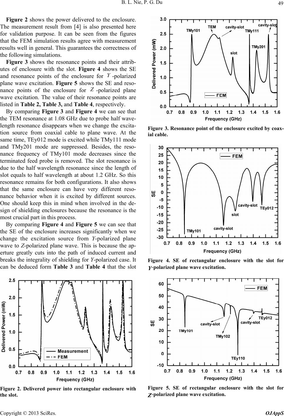 B. L. Nie, P. G. Du 49 Figure 2 shows the power delivered to the enclosure. The measurement result from [4] is also presented here for validation purpose. It can be seen from the figures that the FEM simulation results agree with measurement results well in general. This guarantees the correctness of the following simulations. Figure 3 shows the resonance points and their attrib- utes of enclosure with the slot. Figure 4 shows the SE and resonance points of the enclosure for -polarized plane wave excitation. Figure 5 shows the SE and reso- nance points of the enclosure for Y Z -polarized plane wave excitation. The value of their resonance points are listed in Table 2, Table 3, and Table 4, respectively. By comparing Figure 3 and Figure 4 we can see that the TEM resonance at 1.08 GHz due to probe half wave- length resonance disappears when we change the excita- tion source from coaxial cable to plane wave. At the same time, TEy012 mode is excited while TMy111 mode and TMy201 mode are suppressed. Besides, the reso- nance frequency of TMy101 mode decreases since the terminated feed probe is removed. The slot resonance is due to the half wavelength resonance since the length of slot equals to half wavelength at about 1.2 GHz. So this resonance remains for both configurations. It also shows that the same enclosure can have very different reso- nance behavior when it is excited by different sources. One should keep this in mind when involved in the de- sign of shielding enclosures because the resonance is the most crucial part in this process. By comparing Figure 4 and Figure 5 we can see that the SE of the enclosure increases significantly when we change the excitation source from Y-polarized plane wave to Z-polarized plane wave. This is because the ap- erture greatly cuts into the path of induced current and breaks the integrality of shielding for Y-polarized case. It can be deduced form Table 3 and Table 4 that the slot Figure 2. Delivered power into rectangular enclosure with the slot. Figure 3. Resonance point of the enclosure excited by coax- ial cable. Figure 4. SE of rectangular enclosure with the slot for Y-polarized plane wave excitation. Figure 5. SE of rectangular enclosure with the slot for Z-polarized plane wave excitation. Copyright © 2013 SciRes. OJAppS 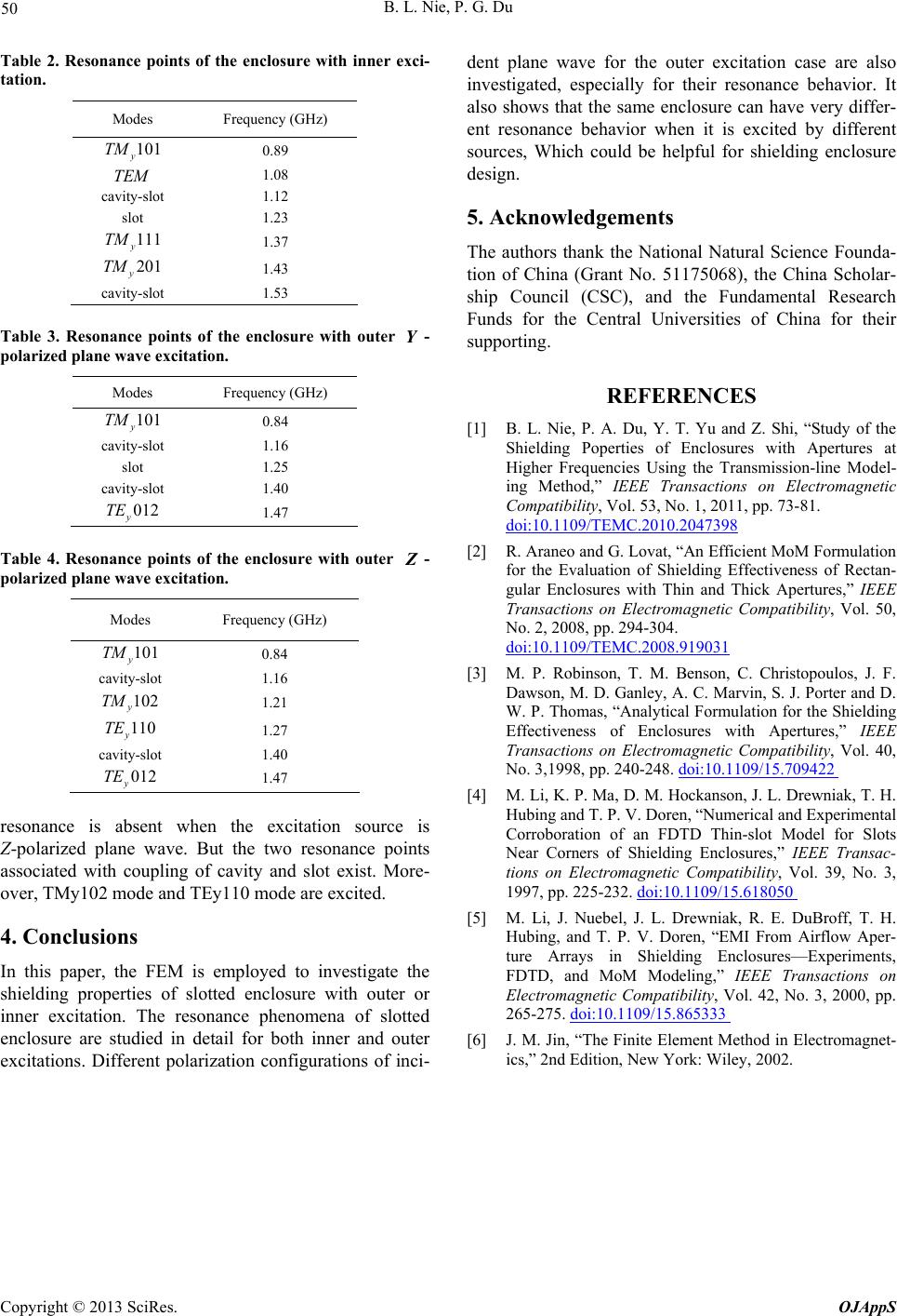 B. L. Nie, P. G. Du Copyright © 2013 SciRes. OJAppS 50 Table 2. Resonance points of the enclosure with inner exci- tation. Modes Frequency (GHz) 101 y TM 0.89 TEM 1.08 cavity-slot 1.12 slot 1.23 111 y TM 1.37 201 y TM 1.43 cavity-slot 1.53 Table 3. Resonance points of the enclosure with outer - polarized plane wave excitation. Y Modes Frequency (GHz) 101 y TM 0.84 cavity-slot 1.16 slot 1.25 cavity-slot 1.40 012 y TE 1.47 Table 4. Resonance points of the enclosure with outer - polarized plane wave excitation. Z Modes Frequency (GHz) 101 y TM 0.84 cavity-slot 1.16 102 y TM 1.21 110 y TE 1.27 cavity-slot 1.40 012 y TE 1.47 resonance is absent when the excitation source is Z-polarized plane wave. But the two resonance points associated with coupling of cavity and slot exist. More- over, TMy102 mode and TEy110 mode are excited. 4. Conclusions In this paper, the FEM is employed to investigate the shielding properties of slotted enclosure with outer or inner excitation. The resonance phenomena of slotted enclosure are studied in detail for both inner and outer excitations. Different polarization configurations of inci- dent plane wave for the outer excitation case are also investigated, especially for their resonance behavior. It also shows that the same enclosure can have very differ- ent resonance behavior when it is excited by different sources, Which could be helpful for shielding enclosure design. 5. Acknowledgements The authors thank the National Natural Science Founda- tion of China (Grant No. 51175068), the China Scholar- ship Council (CSC), and the Fundamental Research Funds for the Central Universities of China for their supporting. REFERENCES [1] B. L. Nie, P. A. Du, Y. T. Yu and Z. Shi, “Study of the Shielding Poperties of Enclosures with Apertures at Higher Frequencies Using the Transmission-line Model- ing Method,” IEEE Transactions on Electromagnetic Compatibility, Vol. 53, No. 1, 2011, pp. 73-81. doi:10.1109/TEMC.2010.2047398 [2] R. Araneo and G. Lovat, “An Efficient MoM Formulation for the Evaluation of Shielding Effectiveness of Rectan- gular Enclosures with Thin and Thick Apertures,” IEEE Transactions on Electromagnetic Compatibility, Vol. 50, No. 2, 2008, pp. 294-304. doi:10.1109/TEMC.2008.919031 [3] M. P. Robinson, T. M. Benson, C. Christopoulos, J. F. Dawson, M. D. Ganley, A. C. Marvin, S. J. Porter and D. W. P. Thomas, “Analytical Formulation for the Shielding Effectiveness of Enclosures with Apertures,” IEEE Transactions on Electromagnetic Compatibility, Vol. 40, No. 3,1998, pp. 240-248. doi:10.1109/15.709422 [4] M. Li, K. P. Ma, D. M. Hockanson, J. L. Drewniak, T. H. Hubing and T. P. V. Doren, “Numerical and Experimental Corroboration of an FDTD Thin-slot Model for Slots Near Corners of Shielding Enclosures,” IEEE Transac- tions on Electromagnetic Compatibility, Vol. 39, No. 3, 1997, pp. 225-232. doi:10.1109/15.618050 [5] M. Li, J. Nuebel, J. L. Drewniak, R. E. DuBroff, T. H. Hubing, and T. P. V. Doren, “EMI From Airflow Aper- ture Arrays in Shielding Enclosures—Experiments, FDTD, and MoM Modeling,” IEEE Transactions on Electromagnetic Compatibility, Vol. 42, No. 3, 2000, pp. 265-275. doi:10.1109/15.865333 [6] J. M. Jin, “The Finite Element Method in Electromagnet- ics,” 2nd Edition, New York: Wiley, 2002. |