

Paper Menu >>
Journal Menu >>
 Open Journal of Applied Sciences, 2013, 3, 30-34 doi:10.4236/ojapps.2013.32B006 Published Online June 2013 (http://www.scirp.org/journal/ojapps) Fault Ride-Through Capability Enhancement of PV System with Voltage Support Control Strategy* Dehui Zeng, Gang Wang, Guoqing Pan, Haifeng Li School of Electric Power, South China University of Technology, Guangzhou, China Email: [email protected], [email protected] Received 2013 ABSTRACT With continuously increasing of photovoltaic (PV) plant’s penetration, it has become a critical issue to improve the fault ride-through capability of PV plant. This paper refers to the German grid code, and the PV system is controlled to keep grid connected, as well as inject reactive current to grid when fault occurs. The mathematical model of PV system is established and the fault characteristic is studied with respect to the control strategy. By analyzing the effect of reactive power supplied by the PV system to the point of common coupling (PCC) voltage, this paper proposes an adaptive voltage support control strategy to enhance the fault ride-through capability of PV system. The control strategy fully utilizes the PV system’s capability of voltage support and takes the safety of equipment into account as well. At last, the proposed control strategy is verified by simulation. Keywords: PV System; Fault Ride-Through; Voltage Support; Control Strategy 1. Introduction Under the pressures of environment pollution and energy shortages, power generation from renewable energy sources has been increasing significantly. Photovoltaic (PV) power generation can be used conveniently and gives no pollution, and has become one of the most widely used distributed generation technologies in recent years[1]. With the increasing of PV penetration, the grid codes from German[2,3], Japan[4] and China[5] have required the PV system to have the low voltage ride-through ca- pability, which defines as the PV inverters’ capability of remaining grid-connected in the event of grid failures. What’s more, in the German grid code, the PV inverter is required to supply reactive power when voltage drops, so as to support the voltage. This requirement can make full use of the auxiliary functions of PV plant, which would take benefit to the participation of the PV plant[6]. On the other hand, the reactive power supplied by the PV plant can support the voltage effectively with high pene- tration of PV plant[7]. Therefore, when voltage drops, making full use of the voltage support capability of the PV plant will lead the trend of grid code in the future. But at the moment, there is no theoretical research on the effect of the reactive power from PV plant to voltage support, which would limit the enhancement of fault ride-through capability of PV system. This paper refers to the German grid code, and the PV inverter is controlled to supply reactive power when voltage drops. The fault characteristic of the PV system is studied with respect to the control strategy. Based on this, the effect of the reactive power from PV inverter to the point of common coupling (PCC) voltage is analyzed and an adaptive voltage support control strategy is pro- posed to enhance the fault ride-through capability of PV system. At last, the proposed control strategy is verified by simulation. 2. PV Inverter Mathematical Model and Fault Characteristic PV array produces dc current by photovoltaic effect. The maximum power point tracking (MPPT) control strategy is generally used to control the dc voltage to stay at the maximum power point as the volt-ampere characteristic shows serious nonlinearity[8]. With the synchronous reference frame control, the output power of the PV in- verter can be written as: This work is supported by the National Basic Research Program o f China (973 Program) (2009CB219704), the Crucial Field and Key Breakthrough Project in “Guangdong-Hongkong” (No. 2009A0913 00011), Guangdong Special Fund Project of Industry, University and Research Institute Collaboration (2011A090200127,2011A090200074), Guangdong Nature Science Foundation(S2012010008355). outP CCd outP CCq PUI QU I (1) where is magnitude of PCC voltage, and PCC Ud I , q I Copyright © 2013 SciRes. OJAppS 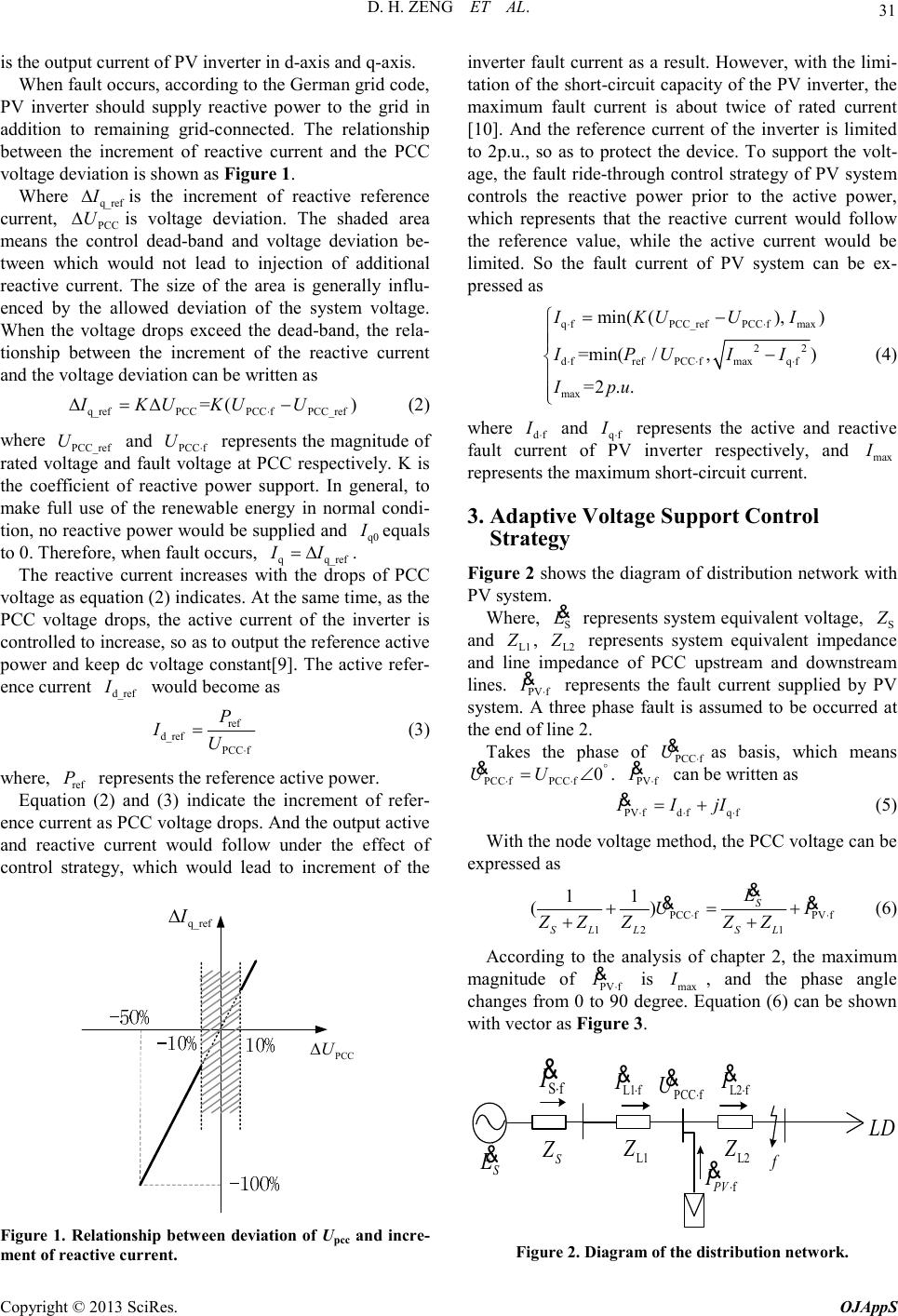 D. H. ZENG ET AL. Copyright © 2013 SciRes. OJAppS 31 is the output current of PV inverter in d-axis and q-axis. When fault occurs, according to the German grid code, PV inverter should supply reactive power to the grid in addition to remaining grid-connected. The relationship between the increment of reactive current and the PCC voltage deviation is shown as Figure 1 . Where q_ref I ∆is the increment of reactive reference current, PCC U∆is voltage deviation. The shaded area means the control dead-band and voltage deviation be- tween which would not lead to injection of additional reactive current. The size of the area is generally influ- enced by the allowed deviation of the system voltage. When the voltage drops exceed the dead-band, the rela- tionship between the increment of the reactive current and the voltage deviation can be written as q_refPCCPCCfPCC_ref =() IKUKUU ⋅ ∆=∆− (2) where PCC_ref U and PCCf U ⋅ represents the magnitude of rated voltage and fault voltage at PCC respectively. K is the coefficient of reactive power support. In general, to make full use of the renewable energy in normal condi- tion, no reactive power would be supplied and q0 I equals to 0. Therefore, when fault occurs, qq_ref II =∆ . The reactive current increases with the drops of PCC voltage as equation (2) indicates. At the same time, as the PCC voltage drops, the active current of the inverter is controlled to increase, so as to output the reference active power and keep dc voltage constant[9]. The active refer- ence current d_ref I would become as ref d_ref PCCf P IU ⋅ = (3) where, ref P represents the reference active power. Equation (2) and (3) indicate the increment of refer- ence current as PCC voltage drops. And the output active and reactive current would follow under the effect of control strategy, which would lead to increment of the PCC U ∆ q_ref I ∆ Figure 1. Relationship between deviation of Upcc and incre- ment of reactive current. inverter fault current as a result. However, with the limi- tation of the short-circuit capacity of the PV inverter, the maximum fault current is about twice of rated current [10]. And the reference current of the inverter is limited to 2p.u., so as to protect the device. To support the volt- age, the fault ride-through control strategy of PV system controls the reactive power prior to the active power, which represents that the reactive current would follow the reference value, while the active current would be limited. So the fault current of PV system can be ex- pressed as qfPCC_refPCCfmax 22 dfrefPCCfmaxqf max min((), ) =min(/,) =2.. IKUUI IPUII Ipu ⋅⋅ ⋅⋅⋅ =− − (4) where df I ⋅ and qf I ⋅ represents the active and reactive fault current of PV inverter respectively, and max I represents the maximum short-circuit current. 3. Adaptive Voltage Support Control Strategy Figure 2 shows the diagram of distribution network with PV system. Where, S E & represents system equivalent voltage, S Z and L1 Z , L2 Z represents system equivalent impedance and line impedance of PCC upstream and downstream lines. PVf I ⋅ & represents the fault current supplied by PV system. A three phase fault is assumed to be occurred at the end of line 2. Takes the phase of PCCf U ⋅ & as basis, which means PCCfPCCf 0 UU ° ⋅⋅ =∠ & . PVf I ⋅ & can be written as PVfdfqf IIjI ⋅⋅⋅ =+ & (5) With the node voltage method, the PCC voltage can be expressed as PCCfPVf 121 11 () S SLLSL E UI ZZZZZ ⋅⋅ +=+ ++ & && (6) According to the analysis of chapter 2, the maximum magnitude of PVf I ⋅ & is max I , and the phase angle changes from 0 to 90 degree. Equation (6) can be shown with vector as Figure 3. L1f I ⋅ & L2f I ⋅ & L1 Z L2 Z PCCf U ⋅ & Sf I ⋅ & f PV I ⋅ & LD f S Z S E & Figure 2. Diagram of the distribution network. 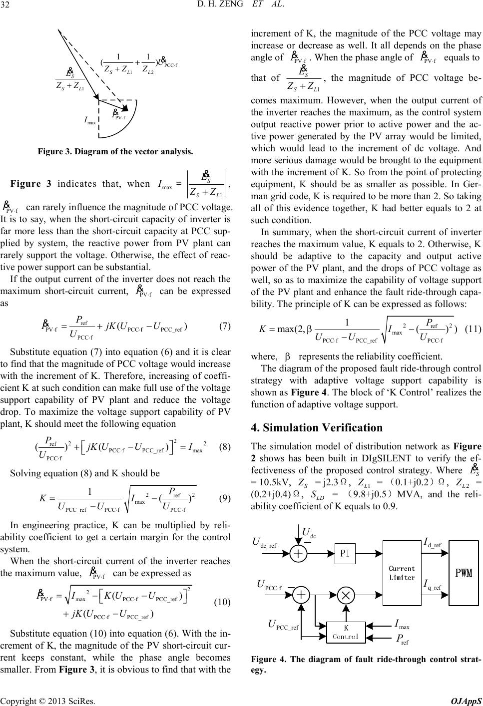 D. H. ZENG ET AL. Copyright © 2013 SciRes. OJAppS 32 1 S SL E ZZ + & PCCf 12 11 () SLL U ZZZ ⋅ + + & PVf I ⋅ & max I Figure 3. Diagram of the vector analysis. Figure 3 indicates that, when max 1 S SL E I ZZ + & =, PVf I ⋅ & can rarely influence the magnitude of PCC voltage. It is to say, when the short-circuit capacity of inverter is far more less than the short-circuit capacity at PCC sup- plied by system, the reactive power from PV plant can rarely support the voltage. Otherwise, the effect of reac- tive power support can be substantial. If the output current of the inverter does not reach the maximum short-circuit current, PVf I ⋅ & can be expressed as ref PVfPCCfPCC_ref PCCf () P IjKUU U ⋅⋅ ⋅ =+− & (7) Substitute equation (7) into equation (6) and it is clear to find that the magnitude of PCC voltage would increase with the increment of K. Therefore, increasing of coeffi- cient K at such condition can make full use of the voltage support capability of PV plant and reduce the voltage drop. To maximize the voltage support capability of PV plant, K should meet the following equation 2 22 ref PCCfPCC_refmax PCCf ()() P jKUUI U⋅ ⋅ +−= (8) Solving equation (8) and K should be 22 ref max PCC_refPCCfPCCf 1 () P KI UUU ⋅⋅ =− − (9) In engineering practice, K can be multiplied by reli- ability coefficient to get a certain margin for the control system. When the short-circuit current of the inverter reaches the maximum value, PVf I ⋅ & can be expressed as 2 2 PVfmaxPCCfPCC_ref PCCfPCC_ref () () IIKUU jKUU ⋅⋅ ⋅ =−− +− & (10) Substitute equation (10) into equation (6). With the in- crement of K, the magnitude of the PV short-circuit cur- rent keeps constant, while the phase angle becomes smaller. From Figure 3, it is obvious to find that with the increment of K, the magnitude of the PCC voltage may increase or decrease as well. It all depends on the phase angle of PVf I ⋅ & . When the phase angle of PVf I ⋅ & equals to that of 1 S SL E ZZ + & , the magnitude of PCC voltage be- comes maximum. However, when the output current of the inverter reaches the maximum, as the control system output reactive power prior to active power and the ac- tive power generated by the PV array would be limited, which would lead to the increment of dc voltage. And more serious damage would be brought to the equipment with the increment of K. So from the point of protecting equipment, K should be as smaller as possible. In Ger- man grid code, K is required to be more than 2. So taking all of this evidence together, K had better equals to 2 at such condition. In summary, when the short-circuit current of inverter reaches the maximum value, K equals to 2. Otherwise, K should be adaptive to the capacity and output active power of the PV plant, and the drops of PCC voltage as well, so as to maximize the capability of voltage support of the PV plant and enhance the fault ride-through capa- bility. The principle of K can be expressed as follows: 22 ref max PCCfPCC_refPCCf 1 max(2,()) P KI UUU β ⋅⋅ =− − (11) where, β represents the reliability coefficient. The diagram of the proposed fault ride-through control strategy with adaptive voltage support capability is shown as Figure 4. The block of ‘K Control’ realizes the function of adaptive voltage support. 4. Simulation Verification The simulation model of distribution network as Figure 2 shows has been built in DIgSILENT to verify the ef- fectiveness of the proposed control strategy. Where S E & = 10.5kV, S Z = j2.3Ω, 1 L Z = (0.1+j0.2)Ω , 2 L Z = (0.2+j0.4)Ω, LD S = (9.8+j0.5)MVA, and the reli- ability coefficient of K equals to 0.9. dc_ref U dc U PCC_ref U PCCf U ⋅ d_ref I q_ref I × max I ref P + + Figure 4. The diagram of fault ride-through control strat- egy. 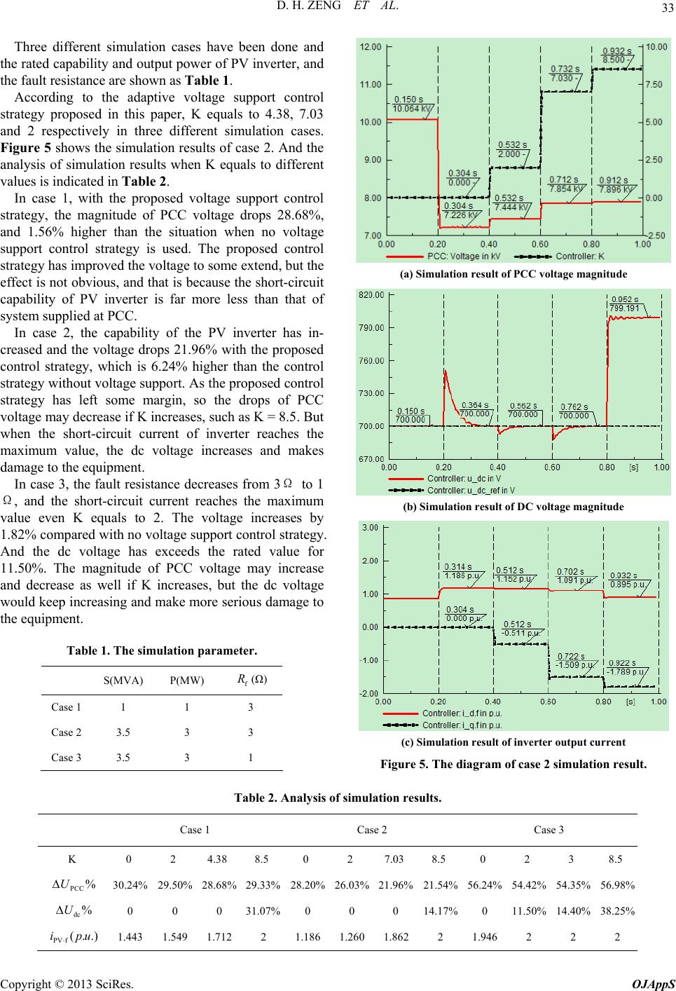 D. H. ZENG ET AL. Copyright © 2013 SciRes. OJAppS 33 Three different simulation cases have been done and the rated capability and output power of PV inverter, and the fault resistance are shown as Table 1. According to the adaptive voltage support control strategy proposed in this paper, K equals to 4.38, 7.03 and 2 respectively in three different simulation cases. Figure 5 shows the simulation results of case 2. And the analysis of simulation results when K equals to different values is indicated in Table 2. In case 1, with the proposed voltage support control strategy, the magnitude of PCC voltage drops 28.68%, and 1.56% higher than the situation when no voltage support control strategy is used. The proposed control strategy has improved the voltage to some extend, but the effect is not obvious, and that is because the short-circuit capability of PV inverter is far more less than that of system supplied at PCC. (a) Simulation result of PCC voltage magnitude In case 2, the capability of the PV inverter has in- creased and the voltage drops 21.96% with the proposed control strategy, which is 6.24% higher than the control strategy without voltage support. As the proposed control strategy has left some margin, so the drops of PCC voltage may decrease if K increases, such as K = 8.5. But when the short-circuit current of inverter reaches the maximum value, the dc voltage increases and makes damage to the equipment. In case 3, the fault resistance decreases from 3Ω to 1 Ω, and the short-circuit current reaches the maximum value even K equals to 2. The voltage increases by 1.82% compared with no voltage support control strategy. And the dc voltage has exceeds the rated value for 11.50%. The magnitude of PCC voltage may increase and decrease as well if K increases, but the dc voltage would keep increasing and make more serious damage to the equipment. (b) Simulation result of DC voltage magnitude Table 1. The simulation parameter. S(MVA) P(MW) f R (Ω) Case 1 1 1 3 Case 2 3.5 3 3 Case 3 3.5 3 1 (c) Simulation result of inverter output current Figure 5. The diagram of case 2 simulation result. Table 2. Analysis of simulation results. Case 1 Case 2 Case 3 K 0 2 4.38 8.5 0 2 7.03 8.5 0 2 3 8.5 PCC %U 30.24% 29.50% 28.68% 29.33%28.20% 26.03%21.96%21.54% 56.24% 54.42% 54.35% 56.98% dc %U 0 0 0 31.07%0 0 0 14.17%0 11.50% 14.40% 38.25% PV f(..)ipu 1.443 1.549 1.712 2 1.1861.2601.862 2 1.946 2 2 2  D. H. ZENG ET AL. Copyright © 2013 SciRes. OJAppS 34 The adaptability of the proposed control strategy has been proved from the simulations, as K equals to different values when the condition changes. With the proposed control strategy, the PV plant’s capability of voltage support can be made full used and the safety of the equipment has been taken into consideration as well. 5. Conclusions This paper refers to the German grid code and control the PV inverter to inject reactive current when the voltage drops. The influence of reactive power from PV system to the PCC voltage is analyzed and an adaptive voltage support control strategy is proposed to improve the fault ride-through capability of PV inverter. The study indi- cates that when the difference between PV inverter short-circuit capacity and the short-circuit capacity at PCC supplied by system is not so large, with the pro- posed control strategy, the voltage can be improved ef- fectively. The proposed control strategy can maximize the voltage support capability of PV plant while takes the safety of equipment into consideration as well. REFERENCES [1] “Trends in Photovoltaic Applications,” IEA Report IEA-PVPS T1-20:2011, 2011. [2] Transmission Code 2007- “Network and System Rules of the German Transmission System Operators,” Verband der Netzbetreiber VDN e.V.beim VDEW, Belin, 2007 [3] E. Troester, “New German Grid Codes for Connecting PV Systems to the Medium Voltage Power Grid,” 2008. http://www.concentrating-pv.org. [4] H. Yamauchi, A. Yona and T. Senjyu, “Design of FRT Capability and Distributed Voltage Control of PV Gen- eration System, ” IEEE Ninth International Conference on Power Electronics and Drive Systems (PEDS) Sinapore, IEEE, December 5-8, 2011, pp. 867- 872. [5] Chinese Enterprise Standards – “Technical Rule for PV Power Station Connected to Power Grid,” Q/GDW 617-2011, SGCC, 2011. [6] R. K. Varma, S. S. Rangarajan, I. Axente and V. Sharma, “Novel Application of A PV Solar Plant as STATCOM during Night and Day in A Distribution Utility Network,” Power Systems Conference and Exposition (PSCE), Phoenix, America, March 20-23, 2011, pp. 1-8. [7] A. Marinopoulos, F. Papandrea, M. Reza, S. Norrga, F. Spertino and R. Napoli, “Grid Integration Aspects of Large Solar PV Installations: LVRT Capability and Reac- tive Power/Voltage Support Requirements,” Power Tech, 2011 IEEE Trondheim, Trondheim, Norway, June 19-23, 2011, pp. 1-8 [8] C. Rodriguez and G. A. J. Amaratunga, “Analytic Solu- tion to the Photovoltaic Maximum Power Point Problem, ” IEEE Transactions on Circuits and Systems I: Regular Papers, Vol. 54, No.9, 2007, pp. 2054-2060. [9] G. Md, S. Islam, A. Al-Durra, S. M. Muyeen and J. Ta- mura, “Low Voltage Ride through Capability Enhance- ment of Grid Connected Large Scale Photovoltaic Sys- tem, ” IECON 2011 - 37th Annual Conference on IEEE Industrial Electronics Society, Melbourne, Australia, November 7-10, 2011, pp. 884-889. [10] H. Nikkhajoei and R. H. Lasseter, “Microgrid Protec- tion,” Power Engineering Society General Meeting, Tampa, USA:IEEE,2007, pp.1-6. |