

Paper Menu >>
Journal Menu >>
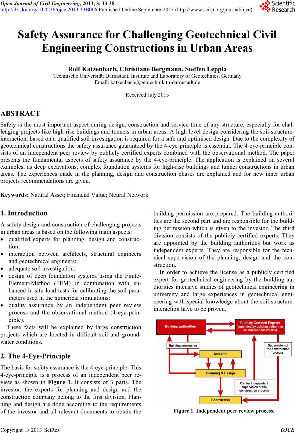 Open Journal of Civil Engineering, 2013, 3, 33-38 http://dx.doi.org/10.4236/ojce.2013.33B006 Published Online September 2013 (http://www.scirp.org/journal/ojce) Copyright © 2013 SciRes. OJCE Safety Assurance for Challenging Geotechnical Civil Engineering Constructions in Urban Areas Rolf Katzenbach, Christiane Bergmann, Steffen Leppla Technische Univers ität Darmstadt, Institute and Laboratory of Geotechnics, German y Email: [email protected] -darmstadt.de Received July 2013 ABSTRACT Safety is the most important aspect during design, construction and service time of any structure, especially for chal- lenging projects like high-rise buildings and tunnels in urban areas. A hi gh level design considering the soil -structure- interaction, based on a qualified soil investigation is required for a safe and optimised design. Due to the complexity of geotechnical co nstructions the safety assurance guaranteed by the 4-eye-principle is essential. The 4-eye-principle con- sists of an independent peer review by publicly certified experts combined with the observational method. The paper presents the fundamental aspects of safety assurance by the 4-eye-principle. The application is explained on several examples, as deep excavations, complex foundation systems for high-rise buildings and tunnel constructions in urban areas. The experiences made in the planning, design and construction phases are explained and for new inner urban projects recommendations are given. Keywords: Natural Asset; Financial Value; Neural Network 1. Introduction A safety design and construction of challenging projects in urban areas is based on the following main aspects: • qualified experts for planning, design and construc- tion; • interaction between architects, structural engineers and geotechnical engineers; • adequate soil investigation; • design of deep foundation systems using the Finite- Element-Method (FEM) in combination with en- hanced in-situ load tests for calibrating the soil para- meters used in the numerical simulations; • quality assurance by an independent peer review process and the observational method (4-eye-prin- ciple). These facts will be explained by large construction projects which are located in difficult soil and ground- water conditions. 2. The 4-Eye-Principle The basis for safety assurance is the 4-eye-principle. T his 4-eye-principle is a process of an independent peer re- view as shown in Figure 1. It consists of 3 parts. The investor, the experts for planning and design and the construction company belong to the first division. Plan- ning and design are done according to the requirements of the investor and all relevant documents to obtain the building permission are prepared. The building authori- ties are the second part and are responsible for the build- ing permission which is given to the investor. The third division consists of the publicly certified experts. They are appointed by the building authorities but work as independent experts. They are responsible for the tech- nical supervision of the planning, design and the con- struction. In order to achieve the license as a publicly certified expert for geotechnical engineering by the building au- thorities intensive studies of geotechnical engineering in university and large experiences in geotechnical engi- neering with special knowledge about the soil-structur e- inter acti on have to b e proven. Figure 1 . Inde pendent peer review proces s . 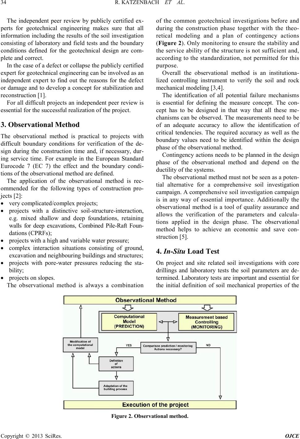 R. KATZENBACH ET AL. Copyright © 2013 SciRes. OJCE 34 The independent peer review by publicly certified ex- perts for geotechnical engineering makes sure that all info rmation includi ng the re sults o f the s oil inve stigation consisting of laboratory and field tests and the boundary conditions defined for the geotechnical design are com- plete and correct. In the case of a defect or collapse the publicly certified expert for geotechnical engineering can be involved as an independent expert to find out the reasons for the defect or damage and to develop a concept for stabilization and reconstruction [1]. For all difficult pr ojects an independ ent peer review is essential for the successful realization of the project. 3. Observational Method The observational method is practical to projects with difficult boundary conditions for verification of the de- sign during the construction time and, if necessary, dur- ing service time. For example in the European Standard Eurocode 7 (EC 7) the effect and the boundary condi- tions of the observational method are defined. The application of the observational method is rec- ommended for the following types of construction pro- jects [2]: • very complicated/complex projects; • projects with a distinctive soil-structure-interaction, e.g. mixed shallow and deep foundations, retaining walls for deep excavations, Combined Pile-Raft Foun- dations (CP RFs); • projects with a high and variable water pressure; • complex interaction situations consisting of ground, excavation and neighbouring bui l dings a nd str uctures; • projects with pore-water pressures reducing the sta- bility; • projects on slopes. The observational method is always a combination of the common geotechnical investigations before and during the construction phase together with the theo- retical modeling and a plan of contingency actions (Fig ure 2). Only monitoring to ensure the stability and the servi ce ability of the structure is not sufficient and, according to the standardization, not permitted for this purpose. Overall the observational method is an institutiona- lized controlling instrument to verify the soil and rock mechanical modeling [3,4]. The identification of all potential failure mechanisms is essential for defining the measure concept. The con- cept has to be designed in that way that all these me- chanisms can be observed. The measurements need to be of an adequate accuracy to allow the identification of critical tendencies. The required accuracy as well as the boundary values need to be identified within the design phase of the observational method. Conti ngency a ctions needs to be planned in the design phase of the observational method and depend on the ductility of the systems. The observational method must not be seen as a poten- tial alternative for a comprehensive soil investigation campaign. A comprehensive soil investigation campaign is in any way of essential importance. Additionally the observational method is a tool of quality assurance and allows the verification of the parameters and calcula- tions applied in the design phase. The observational method helps to achieve an economic and save con- struction [5]. 4. In-Situ Load Test On project and site related soil investigations with core drillings and laboratory tests the soil parameters are de- termined. Laboratory tests are i mportant and essentia l for the initial definition of soil mechanical properties of the Figure 2 . Observat io n al met ho d.  R. KATZENBACH ET AL. Copyright © 2013 SciRes. OJCE 35 soil layer, but usuall y not su fficient for an e ntire and re a- listic capture of the complex conditions, caused by the interaction of subsoil and construction [6]. In order to reliably determine the ultimate bearing ca- pacity of piles, load tests need to be carried out [7]. For pile load tests often very high counter weights or strong anchor systems are necessary. By using the Osterberg method high loads can be reached without installing anchors or counter weights. Hydraulic jacks induce the load in the pile using the pile itself partly as abutment. The results of the field tests allow a calibration of the numerical simulations. The principle scheme of pile load tests is shown in Figure 3. 5. Examples for Engineering Practice 5.1. Classic Pile Foundation for a High-Rise Building in Frankfurt Clay and Limestone In the downtown of Frankfurt am Main, Germany, on a construction site of 17,400 m2 the high-rise building project “PalaisQuartier” has been realized (Figure 4). The cons truct ion was f i nishe d in 20 10. The complex consists of several structures with a total of 180,000 m2 floor space, thereof 60,000 m2 under- ground (Figure 5). The project includes the historic building “Thurn-und Taxis-Palais” whose façade has bee n preser ved (Unit A). The o ffice buildi ng (Unit B) , which is the highest building of the project with a height of 136 m has 34 floors each with a floor space of 1 340 m2. The hotel build ing (Unit C) has a height of 99 m with 24 upper floors. The retail area (Unit D) runs along the total length of the eastern part of the site and consists of eight upper floors with a total height of 43 m. The und er gro und p ar ki ng gar a ge wit h fi ve fl oo r s sp a ns across the complete project area. With an 8 m high first sublevel, partially with mezzanine floor, and four more Figure 3 . Principle sche me of pile load tests. Figure 4 . “Palai sQuartier”, Frankfurt am Main, Germany. Figure 5. “PalaisQuartier”, Frankfurt am Main, Germany: plan v iew ( top) and cr oss section A-A (bottom). sub-levels the foundation depth results to 22 m below ground level. Thereby excavation bottom is at 80 m above sea level (msl). A total of 302 foundation piles (diameter up to 1.86 m, length up to 27 m) reach down to  R. KATZENBACH ET AL. Copyright © 2013 SciRes. OJCE 36 depths of 53.2 m to 70.1 m. above sea level depending on the structural requireme nts. The pile head of the 543 r etaining wall piles (dia meter 1.5 m, length up to 38 m) were located between 94.1 m and 99.6 m above sea level, the pile base was between 59.8 m and 73.4 m above sea level depending on the structural requirements. As shown in the sectional view (Figure 6), the upper part of the piles is in the Frankfurt Clay and the base of the piles is set in the rocky Frank- furt Li me s t o ne. Regarding the large number of piles and the high pile loads a pile load test has been carried out for optimiza- tion of the classic pile foundation. Osterb erg -Cells (O-Cells) have been installed in two levels in order to assess the influence of pile shaft grouting on the limit skin friction of the piles in the Frankfurt Limestone (Figure 6). The test pile with a to tal length of 12.9 m and a diameter of 1.68 m consist of three segments and has been installed in the Frankfurt Limestone layer 31.7 m below ground level. The upper pile segment above the upper cell level and the middle pile segment between the two cell levels can be tested independently. In the first Figure 6 . Pile l oad test setup. phase of the test the upper part was loaded by using the middle and the lo wer part as abutment. A limit of 24 MN could be reached (Figure 7). The upper segment was lifted about 1.5 cm, the settlement of the middle and lower part was 1.0 cm. The mobilized shaft friction was about 830 kN/m2. Subsequently the upper pile segment was uncoupled by discharging the upper cell level. In the second test phase the middle pile segment was loaded by using the lower segment as abutment. The li mit load of the middle segment with shaft grouting was 27.5 MN (Figure 7). The skin fric tion was 1040 kN/m2, this means 2 4% high- er tha n wit ho ut s haf t gr o ut in g. B a se d o n the r esul t s o f t he pile load test using O-Cells th e majority of the 290 foun- dation piles were made by applying shaft grouting. Due to pile load test the total length of was reduced signifi- cantly. 5.2. CPRF for a High-Ris e Bu ilding in Clay Marl In the scope of the project Mirax Plaza in Kiev, Ukraine, 2 high-rise buildings, each of them 192 m (46 storeys) high, a shopping and entertainment mall and an under- ground parking are under construction (Figure 8). The Fig ure 7. Load di splace ment curve of tes t phas e 1 (t op) and test phase 2 (bottom). 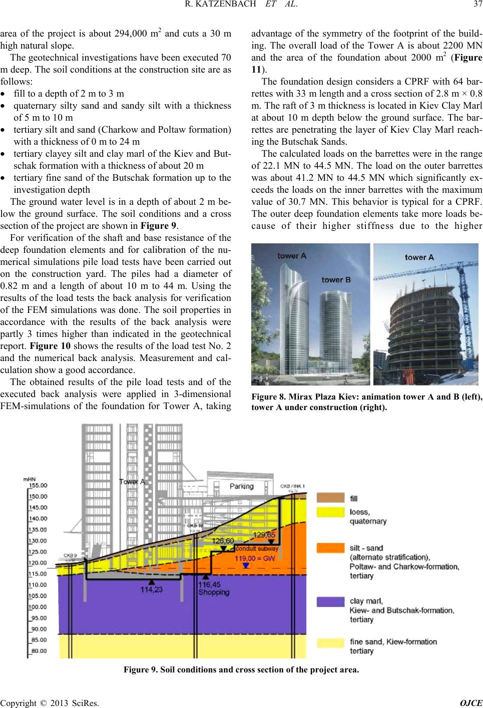 R. KATZENBACH ET AL. Copyright © 2013 SciRes. OJCE 37 area of the project is about 294,000 m2 and cuts a 30 m high nat ura l s lo pe . The geotechnical investigations have been executed 70 m deep. The soil conditions at the construction site are as follows: • fill to a depth of 2 m to 3 m • quaternary silty sand and sandy silt with a thickness of 5 m to 10 m • tertiar y silt and sand ( Charko w a nd P olta w formatio n) with a thickness of 0 m to 24 m • tertiar y clayey silt and cla y marl of the Kiev and B ut- schak formation with a thickness of about 20 m • tertiary fine sand of the Butschak formation up to the investigation depth The ground water level is in a depth of about 2 m be- low the ground surface. The soil conditions and a cross section of the project are shown in Figure 9. For verification of the shaft and base resistance of the deep foundation elements and for calibration of the nu- merical simulations pile load tests have been carried out on the construction yard. The piles had a diameter of 0.82 m and a length of about 10 m to 44 m. Using the results of the load tests t he back analysis for verification of the FEM simulations was done. The soil properties in accordance with the results of the back analysis were partly 3 times higher than indicated in the geotechnical report. Figure 10 sho ws the r esults o f the load test No. 2 and the numerical back analysis. Measurement and cal- culation show a good accordance. The obtained results of the pile load tests and of the executed back analysis were applied in 3-dimensional FEM-simulations of the foundation for Tower A, taking advantage of the symmetry of the footprint of the build- ing. The overall load of the Tower A is about 2200 MN and the area of the foundation about 2000 m2 (Figure 11). The foundation design considers a CPRF with 64 bar- rettes with 33 m length and a cross section of 2.8 m × 0.8 m. T he raft of 3 m thick ness i s loca ted in K iev Clay Mar l at about 10 m depth below the ground surface. The bar- rettes are penetrating the layer of Kiev Clay Marl reach- ing the Butschak Sand s. The calculated loads on the barrettes were in the range of 22.1 MN to 44.5 MN. The load on the outer barrettes was about 41.2 MN to 44.5 MN which significantly ex- ceeds the loads on the inner barrettes with the maximum value of 30.7 MN. This behavior is typical for a CPRF. The outer deep foundation elements take more loads be- cause of their higher stiffness due to the higher Figure 8 . Mi rax Plaza Ki ev: ani matio n tower A a nd B (l eft), tower A under construc tion (right). Figure 9 . Soil conditions and cross secti on of the proj ect area. 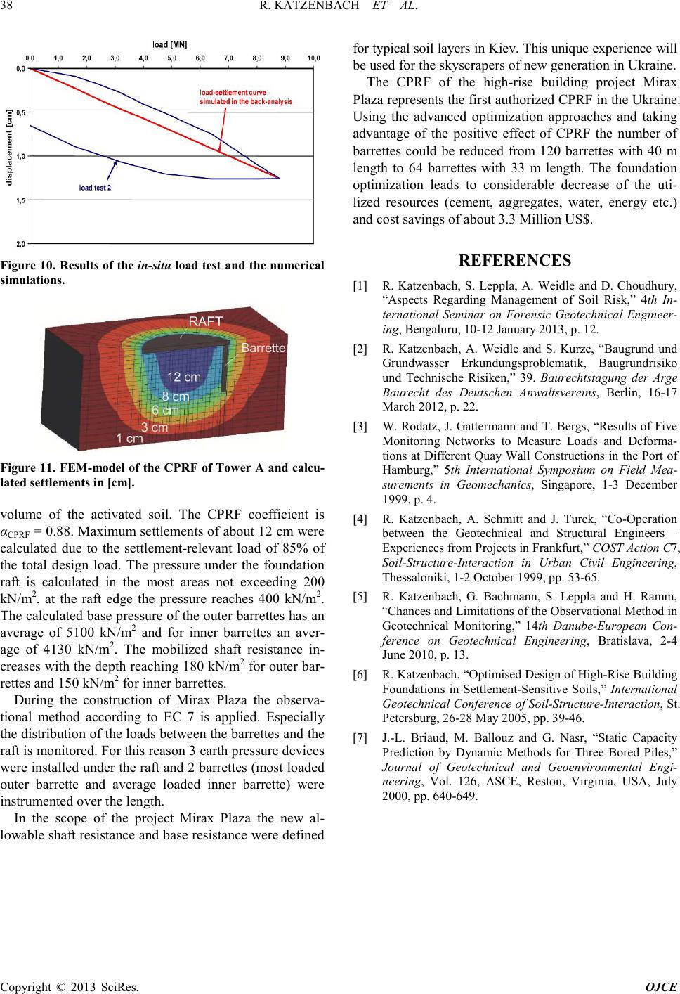 R. KATZENBACH ET AL. Copyright © 2013 SciRes. OJCE 38 Figure 10. Results of the in-situ load test and the nu merical si mulati ons. Figure 11. FEM-model of the CPRF of Tow er A and calcu- lated settlements in [cm]. volume of the activated soil. The CPRF coefficient is αCPRF = 0.88. Maximum settlements of about 12 cm were calculated due to the settlement-relevant load of 85% of the total design load. The pressure under the foundation raft is calculated in the most areas not exceeding 200 kN/m2, at the raft edge the pressure reaches 400 kN/m2. The calculated base pressure of the outer barrettes has an average of 5100 kN/m2 and for inner barrettes an aver- age of 4130 kN/m2. The mobilized shaft resistance in- creases with the depth reaching 180 kN/m2 for outer bar- rettes and 150 kN/m2 for inner barrettes. During the construction of Mirax Plaza the observa- tional method according to EC 7 is applied. Especially the distributio n of the loads bet ween the barrettes and the raft is monitored. For this reason 3 earth pressure devices were installed under the raft and 2 barrettes (most loaded outer barrette and average loaded inner barrette) were instrume nted over the length. In the scope of the project Mirax Plaza the new al- lowable shaft resistance and base resistance were defined for t ypic al soi l layer s in K iev. T his uni que e xper ienc e wil l be used fo r the skyscra per s of new generation in Ukraine. The CPRF of the high-rise building project Mirax Plaza represents the first authorized CPRF in the Ukraine. Using the advanced optimization approaches and taking advantage of the positive effect of CPRF the number of barrettes could be reduced from 120 barrettes with 40 m length to 64 barrettes with 33 m length. The foundation optimization leads to considerable decrease of the uti- lized resources (cement, aggregates, water, energy etc.) and cost savings of about 3.3 Million US$. REFERENCES [1] R. Katzenbach, S. Leppla, A. Weidle and D. Choudhury, “Aspects Regarding Management of Soil Risk,” 4th In- ternational Seminar on Forensic Geotechnical Engineer- ing, Bengaluru, 10-12 Januar y 2013, p. 12 . [2] R. Katzenbach, A. Weidle and S. Kurze, “Baugrund und Grundwasser Erkundungsproblematik, Baugrundrisiko und Technische Risiken,” 39. Baurechtstagung der Arge Baurecht des Deutschen Anwaltsvereins, Berlin, 16-17 March 2012, p. 22. [3] W. Rodatz, J. Gattermann and T. Bergs, “Results of Five Monitoring Networks to Measure Loads and Deforma- tions at Different Quay Wall Constructions in the Port of Hamburg,” 5th International Symposium on Field Mea- surements in Geomech anics, Singapore, 1-3 December 1999, p. 4. [4] R. Katzenbach, A. Schmitt and J. Turek, “Co-Operation between the Geotechnical and Structural Engineers— Experien ces fro m P rojects in Frankfurt ,” COST Action C7, Soil-Structure-Interaction in Urban Civil Engineering, Thessaloniki, 1-2 Octobe r 19 99, pp. 53 -65. [5] R. Katzenbach, G. Bachmann, S. Leppla and H. Ramm, “Chances and Limitations of the Observational Method in Geotechnical Monitoring,” 14th Danube-European Con- ference on Geotechnical Engineering, Bratislava, 2-4 June 201 0, p. 13. [6] R. K atzen bach , “Opt imised Desi gn of High-Rise Building Foundations in Settlement-Sensitive Soils,” International Geotechnical Conference of Soil-Structure-Interaction, St. Petersburg, 26-28 May 2005, pp. 39-46. [7] J.-L. Briaud, M. Ballouz and G. Nasr, “Static Capacity Prediction by Dynamic Methods for Three Bored Piles,” Journal of Geotechnical and Geoenvironmental Engi- neerin g, Vol. 126, ASCE, Reston, Virginia, USA, July 2000, pp . 640-649. |