

Paper Menu >>
Journal Menu >>
 Journal of Signal and Information Processing, 2013, 4, 364-369 Published Online November 2013 (http://www.scirp.org/journal/jsip) http://dx.doi.org/10.4236/jsip.2013.44046 Open Access JSIP Compression of MR Images Using DWT by Comparing RGB and YCbCr Color Spaces Agrawal Jayprkash1*, Ritu Vijay2 1Department of Electronics and Communication Engineering, Jagnnath Gupta Institute of Engineering and Technology, Jaipur, India; 2AIM & ACT, Banasthali University, Vanasthali, India. Email: *[email protected] Received August 6th, 2013; revised September 6th, 2013; accepted September 16th, 2013 Copyright © 2013 Agrawal Jayprkash, Ritu Vijay. This is an open access article distributed under the Creative Commons Attribution License, which permits unrestricted use, distribution, and reproduction in any medium, provided the original work is properly cited. ABSTRACT This paper consists of a lossy image compression algorithm dedicated to the medical images doing comparison of RGB and YCbCr color space. Several lossy/lossless transform coding techniques are used for medical image compression. Discrete Wavelet Transform (DWT) is one such widely used technique. After a preprocessing step (remove the mean and RGB to YCbCr transformation), the DWT is applied and followed by the bisection method including thresholding, the quantization, dequantization, the Inverse Discrete Wavelet Transform (IDWT), YCbCr to RGB transform of mean recovering. To obtain the best compression ratio (CR), the next step encoding algorithm is used for compressing the input medical image into three matrices and forward to DWT block a corresponding containing the maximum possible of run of zeros at its end. The last step decoding algorithm is used to decompress the image using IDWT that is applied to get three matrices of medical image. Keywords: Magnetic Resonance Image (MRI); RGB; YCbCr Transform; Block-Based DWT; Transform Coding 1. Introduction The basic objective of image compression is to reduce the size of image data for transmission or store in an effi- cient manner, while maintaining the suitable quality of reconstructed images [1-3]. The easy and reliable digital transmission and storage of biomedical images would be a tremendous boon to the medical practices. This can help in instant availability of earlier imaging studies when patients are re-admitted [4-6]. Both Medical and surgical teams indulging on patient care could have simultaneous access to imaging studies on monitors throughout the hospital. This long-term digital archiving or rapid transmission is prohibitive without the use of image compression to reduce the file sizes. There are two basic types of image compression schemes: The first lossless compression scheme encodes and decodes the data perfectly and the reconstructed image matches exactly with the original image, which means there is no loss of data with no degradation. In this scheme the coding techniques are Huffman encoding, entropy encoding, and run length ending. The second lossy compression scheme is used for the sake of using a minimum storage space. In this scheme there is a trade-off between compression and image qual- ity. In lossy compression, the final decompressed image must be visually lossless and consist of removing the redundant information in adjacent pixels to minimize the number of bits [7-9]. In preprocessing step, many decorrelating transforms like YCbCr, YUV, YIQ [10-12] are used to reduce the correlation between the R, G and B plane. We can pref- erably use one of these color space transforms before the application of wavelet transform. In this paper we are considering the YCbCr transform to reduce the correla- tion between the R, G and B space [13]. Block-based DWT [9,14] Shown in Figure 1, decom- poses a broadband signal into two subbands with smaller bandwidths and slower sample rates. A series of HP and LP FIR filters are used to repeatedly divide the input frequency range. The input signals are in the form of frames having a frame size as multiple of 2n, where n is the number of levels. Each unit consists of an LP and HP FIR filter pair. The halfband filters with a cutoff fre- *Corresponding author. 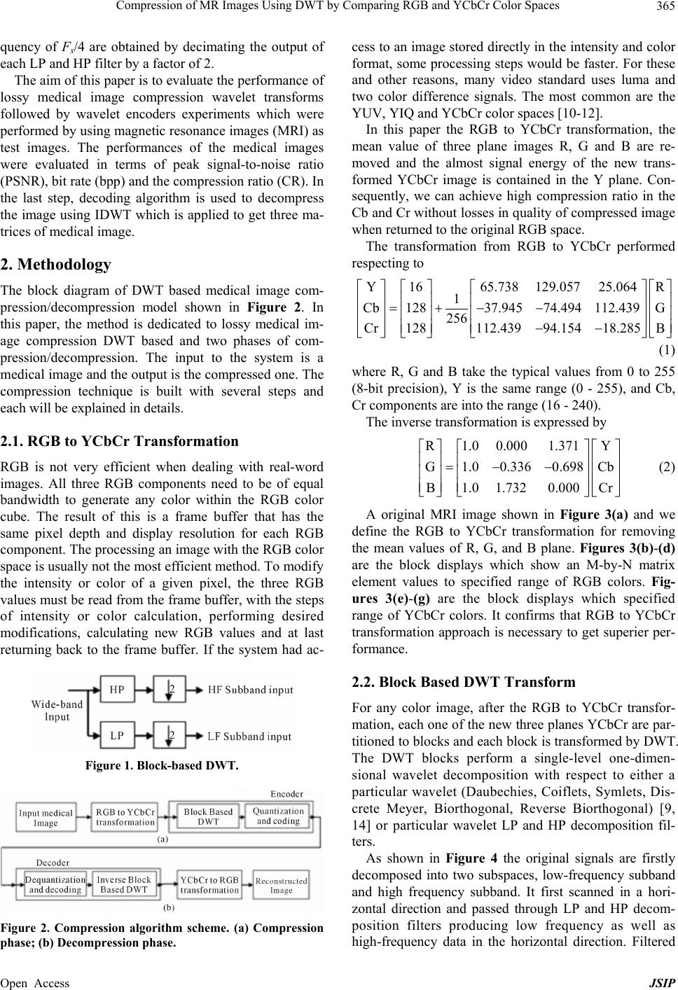 Compression of MR Images Using DWT by Comparing RGB and YCbCr Color Spaces 365 quency of Fs/4 are obtained by decimating the output of each LP and HP filter by a factor of 2. The aim of this paper is to evaluate the performance of lossy medical image compression wavelet transforms followed by wavelet encoders experiments which were performed by using magnetic resonance images (MRI) as test images. The performances of the medical images were evaluated in terms of peak signal-to-noise ratio (PSNR), bit rate (bpp) and the compression ratio (CR). In the last step, decoding algorithm is used to decompress the image using IDWT which is applied to get three ma- trices of medical image. 2. Methodology The block diagram of DWT based medical image com- pression/decompression model shown in Figure 2. In this paper, the method is dedicated to lossy medical im- age compression DWT based and two phases of com- pression/decompression. The input to the system is a medical image and the output is the compressed one. The compression technique is built with several steps and each will be explained in details. 2.1. RGB to YCbCr Transformation RGB is not very efficient when dealing with real-word images. All three RGB components need to be of equal bandwidth to generate any color within the RGB color cube. The result of this is a frame buffer that has the same pixel depth and display resolution for each RGB component. The processing an image with the RGB color space is usually not the most efficient method. To modify the intensity or color of a given pixel, the three RGB values must be read from the frame buffer, with the steps of intensity or color calculation, performing desired modifications, calculating new RGB values and at last returning back to the frame buffer. If the system had ac- Figure 1. Block-based DWT. Figure 2. Compression algorithm scheme. (a) Compression phase; (b) Decompression phase. cess to an image stored directly in the intensity and color format, some processing steps would be faster. For these and other reasons, many video standard uses luma and two color difference signals. The most common are the YUV, YIQ and YCbCr color spaces [10-12]. In this paper the RGB to YCbCr transformation, the mean value of three plane images R, G and B are re- moved and the almost signal energy of the new trans- formed YCbCr image is contained in the Y plane. Con- sequently, we can achieve high compression ratio in the Cb and Cr without losses in quality of compressed image when returned to the original RGB space. The transformation from RGB to YCbCr performed respecting to Y1665.738 129.05725.064R 1 Cb12837.94574.494 112.439G 256 Cr128112.43994.15418.285 B (1) where R, G and B take the typical values from 0 to 255 (8-bit precision), Y is the same range (0 - 255), and Cb, Cr components are into the range (16 - 240). The inverse transformation is expressed by R1.0 0.0001.371Y G1.00.3360.698 Cb B1.0 1.7320.000Cr (2) A original MRI image shown in Figure 3(a) and we define the RGB to YCbCr transformation for removing the mean values of R, G, and B plane. Figures 3(b)-(d) are the block displays which show an M-by-N matrix element values to specified range of RGB colors. Fig- ures 3(e)-(g) are the block displays which specified range of YCbCr colors. It confirms that RGB to YCbCr transformation approach is necessary to get superier per- formance. 2.2. Block Based DWT Transform For any color image, after the RGB to YCbCr transfor- mation, each one of the new three planes YCbCr are par- titioned to blocks and each block is transformed by DWT. The DWT blocks perform a single-level one-dimen- sional wavelet decomposition with respect to either a particular wavelet (Daubechies, Coiflets, Symlets, Dis- crete Meyer, Biorthogonal, Reverse Biorthogonal) [9, 14] or particular wavelet LP and HP decomposition fil- ters. As shown in Figure 4 the original signals are firstly decomposed into two subspaces, low-frequency subband and high frequency subband. It first scanned in a hori- zontal direction and passed through LP and HP decom- position filters producing low frequency as well as high-frequency data in the horizontal direction. Filtered Open Access JSIP  Compression of MR Images Using DWT by Comparing RGB and YCbCr Color Spaces Open Access JSIP 366 Figure 3. (a) Original test MRI image; (b)-(d) are the block displays an M × N matrix element values to specified range of RGB colors; (e)-(g) are the block displays specified range of YCbCr colors. Figure 4. Pyramidal algorithm of one-level forward DWT decomposition. output data are then scanned in a vertical direction and again these filters are applied separately to generate dif- ferent frequency subbands. The transform generates sub- bands LL, LH, HL and HH each with one-fourth the size of the original image. Most of the energy is concentrated in low-frequency subband LL, whereas higher-frequency subbands LH, HL and HH contain detailed information of the image in vertical, horizontal and diagonal direc- tions, respectively. For higher level decomposition, DWT can be applied again to the LL subband recursively in a similar way to further compact energy into fewer low- frequency coefficients. The appropriate choice of filters for the transform is very important to achieve high cod- ing efficiency. 2.3. Quantization and Transform Coding A transform coder decomposes a signal in an orthogonal basis and quantizes the decomposition coefficients [15]. The distortion of the restored signal is minimized by op- timizing the quantization, the basis, and the bit allocation. It is desirable to perform quantization by dividing the transformed coefficients by quantization value. For low frequency, coefficients are divided by smaller values while the high frequency coefficients are divided by lar- ger values In this paper, we code the data using transform coding scheme of following steps: Source coding is to represent information in bits, with the natural aim of using a small number of bits. The “in- formation” is denoted by a real column vector or a sequence of such vectors. A vector might be formed from pixel values in an image; K. N pixels can be ar- ranged as a sequence of K vectors of length N. The vec- tor length N is defined such that each vector in a se- quence is encoded independently. 2 x Transform codes are the most used source codes be- cause they are easy to apply at any rate and even with very large values of N. The essence of transform coding is the modularization shown in the Figure 5 first, an in- vertible linear transform of the source vector x is com- puted, producing y = Tx. Each component of y is called a transform coefficient. The N transform coefficients are then quantized independently of each other by N scalar quantizers. A quantizer q is a mapping from a source alphabet to a reproduction code. It can be decomposed into two operations N q . The lossy encoder is specified by a partition of into partition cells N N 2,xii t Sx and the reproduction de- coder is . If N = 1, the quantizer is called a scalar quantizer and if N ˃ 1, it is vector quantizer. :N Several quality measures can be found in open litera- ture of the field. The mean square error (MSE) and the Peak signal to noise ratio (PSNR) are the most used  Compression of MR Images Using DWT by Comparing RGB and YCbCr Color Spaces 367 Figure 5. Transform coding scheme: A source code can be decomposed so that the encoder is a linear transform T and a set of N scalar quantizer encoders. In decoder are N sca- lar quantizer decoders and another linear transform U. Usually U = T−1. measures. Mean square error (MSE) is the some sort of average or sum of the squares of the error between two images. For M × N images u(m, n) and û(m, n), the least square error (LSE) is, 2 11 1ˆ LSE, , MN mn umn umn MN (3) and average LSE is called the Mean square error (MSE), 2 11 1ˆ MSE, , MN mn Eumn umn MN (4) where u(m, n) and û(m, n) are the original and recon- structed intensities belonging to R, G and B plane. The PSNR is defined in decibels (dB) as, 2 10 PSNR10log MSE (5) where 2 is the variance of the original image. For medical image we used the relation given as 2 10 3 PSNR 10logMSE RMSE GMSE B (6) The size of the compressed image is evaluated with the CR or Bit-rate per pixel (BPP), defined by Original image size in bits CR compressed image in bits (7) The various steps during compression and decompres- sion algorithms are summarized as follows: Compression algorithm: 1) Input: Medical image I(RGB); 2) Break the input image into three matrices I(R), I(G) and I(B); 3) Transformation of the I(R), I(G) and I(B) matrices into I(Y), I(Cb) and I(Cr); 4) Perform DWT transform of sub-band I(Y), I(Cb) and I(Cr) separately; 5) Transform coder decomposes and quantizes the de- composition coefficients; 6) Output: Compressed medical image I(YCbCr). Decompression algorithm: 1) Input: Compressed medical image I(YCbCr); 2) Inverse sub-band transform and dequantization of reproduction code; 3) IDWT is applied and get Î(Y), Î(Cb) and Î(Cr); 4) Transformation of the Î(Y), Î(Cb) and Î(Cr) into Î(R), Î (G) and Î (B); 5) Convert Î(R), Î(G) and Î(B) to Î(RGB); 6) Output: Decompressed medical image Î(RGB). 3. Results Various results got hold of and summarized after per- forming different experiment with YCbCr color space on standard medical MR images (Figure 6). The YCbCr transform applied in RGB color space and the respective reconstructed images are shown in Figure 7. Different size images were tested on the different color images both in the RGB space and in the YCbCr color space. Table 1 shows the results demonstrating, the superior- ity of performance of the proposed technique when working in the YCbCr domain. From the Table, it ob- serve that PSNR in YCbCr color space increased and the percentage of increased PSNR in Cb and Cr color space is high. Similarly it is observed that, bpp is high in YCbCr color space as compare to RGB color space. 4. Discussion The major objective of image compression is to reduce the size of the image data for transmission or to obtain the best visual quality with minimum bit utilization. The (a) (b) (c) (d) (e) (f) (i) (j) (h) (g) Figure 6. Original test medical MR images. (a) MR1; (b) MR2; (c) MR3; (d) MR4; (e) MR5; (f) MR6; (g) MR7; (h) MR8; (i) MR9 and (j) MR10. (a) (b) (c) (d) (e) (f) (g) (h) (i) (j) Figure 7. Reconstructed medical MR images. (a) MR1; (b) MR2; (c) MR3; (d) MR4; (e) MR5; (f) MR6; (g) MR7; (h) MR8; (i) MR9 and (j) MR10. Open Access JSIP 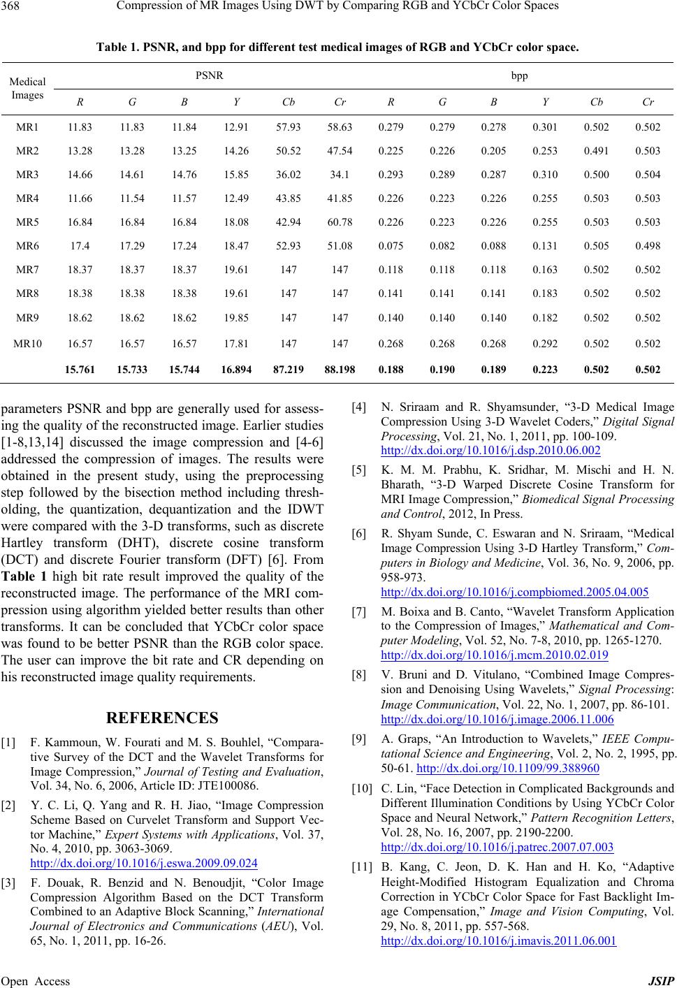 Compression of MR Images Using DWT by Comparing RGB and YCbCr Color Spaces Open Access JSIP 368 Table 1. PSNR, and bpp for different test medical images of RGB and YCbCr color space. PSNR bpp Medical Images R G B Y Cb Cr R G B Y Cb Cr MR1 11.83 11. 83 11. 84 12.91 57.93 58.63 0.279 0.279 0.278 0.301 0.502 0.502 MR2 13.28 13.28 13.25 14.26 50.52 47.54 0.225 0.226 0.205 0.253 0.491 0.503 MR3 14.66 14.61 14.76 15.85 36.02 34.1 0.293 0.289 0.287 0.310 0.500 0.504 MR4 11.66 11. 54 11. 57 12.49 43.85 41.85 0.226 0.223 0.226 0.255 0.503 0.503 MR5 16.84 16.84 16.84 18.08 42.94 60.78 0.226 0.223 0.226 0.255 0.503 0.503 MR6 17.4 17.29 17.24 18.47 52.93 51.08 0.075 0.082 0.088 0.131 0.505 0.498 MR7 18.37 18.37 18.37 19.61 147 147 0.118 0.118 0.118 0.163 0.502 0.502 MR8 18.38 18.38 18.38 19.61 147 147 0.141 0.141 0.141 0.183 0.502 0.502 MR9 18.62 18.62 18.62 19.85 147 147 0.140 0.140 0.140 0.182 0.502 0.502 MR10 16.57 16.57 16.57 17.81 147 147 0.268 0.268 0.268 0.292 0.502 0.502 15.761 15.733 15.744 16.894 87.21988.1980.188 0.190 0.189 0.223 0.502 0.502 parameters PSNR and bpp are generally used for assess- ing the quality of the reconstructed image. Earlier studies [1-8,13,14] discussed the image compression and [4-6] addressed the compression of images. The results were obtained in the present study, using the preprocessing step followed by the bisection method including thresh- olding, the quantization, dequantization and the IDWT were compared with the 3-D transforms, such as discrete Hartley transform (DHT), discrete cosine transform (DCT) and discrete Fourier transform (DFT) [6]. From Table 1 high bit rate result improved the quality of the reconstructed image. The performance of the MRI com- pression using algorithm yielded better results than other transforms. It can be concluded that YCbCr color space was found to be better PSNR than the RGB color space. The user can improve the bit rate and CR depending on his reconstructed image quality requirements. REFERENCES [1] F. Kammoun, W. Fourati and M. S. Bouhlel, “Compara- tive Survey of the DCT and the Wavelet Transforms for Image Compression,” Journal of Testing and Evaluation, Vol. 34, No. 6, 2006, Article ID: JTE100086. [2] Y. C. Li, Q. Yang and R. H. Jiao, “Image Compression Scheme Based on Curvelet Transform and Support Vec- tor Machine,” Expert Systems with Applications, Vol. 37, No. 4, 2010, pp. 3063-3069. http://dx.doi.org/10.1016/j.eswa.2009.09.024 [3] F. Douak, R. Benzid and N. Benoudjit, “Color Image Compression Algorithm Based on the DCT Transform Combined to an Adaptive Block Scanning,” International Journal of Electronics and Communications (AEU), Vol. 65, No. 1, 2011, pp. 16-26. [4] N. Sriraam and R. Shyamsunder, “3-D Medical Image Compression Using 3-D Wavelet Coders,” Digital Signal Processing, Vol. 21, No. 1, 2011, pp. 100-109. http://dx.doi.org/10.1016/j.dsp.2010.06.002 [5] K. M. M. Prabhu, K. Sridhar, M. Mischi and H. N. Bharath, “3-D Warped Discrete Cosine Transform for MRI Image Compression,” Biomedical Signal Processing and Control, 2012, In Press. [6] R. Shyam Sunde, C. Eswaran and N. Sriraam, “Medical Image Compression Using 3-D Hartley Transform,” Com- puters in Biology and Medicine, Vol. 36, No. 9, 2006, pp. 958-973. http://dx.doi.org/10.1016/j.compbiomed.2005.04.005 [7] M. Boixa and B. Canto, “Wavelet Transform Application to the Compression of Images,” Mathematical and Com- puter Modeling, Vol. 52, No. 7-8, 2010, pp. 1265-1270. http://dx.doi.org/10.1016/j.mcm.2010.02.019 [8] V. Bruni and D. Vitulano, “Combined Image Compres- sion and Denoising Using Wavelets,” Signal Processing: Image Communication, Vol. 22, No. 1, 2007, pp. 86-101. http://dx.doi.org/10.1016/j.image.2006.11.006 [9] A. Graps, “An Introduction to Wavelets,” IEEE Compu- tational Science and Engineering, Vol. 2, No. 2, 1995, pp. 50-61. http://dx.doi.org/10.1109/99.388960 [10] C. Lin, “Face Detection in Complicated Backgrounds and Different Illumination Conditions by Using YCbCr Color Space and Neural Network,” Pattern Recognition Letters, Vol. 28, No. 16, 2007, pp. 2190-2200. http://dx.doi.org/10.1016/j.patrec.2007.07.003 [11] B. Kang, C. Jeon, D. K. Han and H. Ko, “Adaptive Height-Modified Histogram Equalization and Chroma Correction in YCbCr Color Space for Fast Backlight Im- age Compensation,” Image and Vision Computing, Vol. 29, No. 8, 2011, pp. 557-568. http://dx.doi.org/10.1016/j.imavis.2011.06.001  Compression of MR Images Using DWT by Comparing RGB and YCbCr Color Spaces 369 [12] J. M. Chaves-Gonzalez, M. A. Vega-Rodriguez, J. A. Gomez-Pulido and J. M. Sanchez-Perez, “Detecting Skin in Face Recognition Systems: A Colour Spaces Study,” Digital Signal Processing, Vol. 20, No. 3, 2010, pp. 806- 823. http://dx.doi.org/10.1016/j.dsp.2009.10.008 [13] S. Kumar Singh and S. Kumar, “Novel Adaptive Color Space Transform and Application to Image Compres- sion,” Signal Processing: Image Communication, Vol. 26, No. 10, 2011, pp. 662-672. http://dx.doi.org/10.1016/j.image.2011.08.001 [14] J. P. Agrawal and R. Vijay, “Wavelet Compression of CT Medical Images,” IJSRET, Vol. 1, No. 3, 2012, pp. 45-51. [15] J. D. Allen, “An Approach to Fast Transform Coding in Software Signal Processing,” Image Communication, Vol. 8, No. 1, 1996, pp. 3-11. http://dx.doi.org/10.1016/0923-5965(94)00047-6 Open Access JSIP |