

Paper Menu >>
Journal Menu >>
 Journal of Signal and Information Processing, 2013, 4, 359-363 Published Online November 2013 (http://www.scirp.org/journal/jsip) http://dx.doi.org/10.4236/jsip.2013.44045 Open Access JSIP 359 Adaptive Enhancement Techniques for Solar Images Mohammad A. A. Al-Rababah1, Abdusamad Al-Marghilani1, Mohammed M. Al-Shomrani2, Ibrahim A. Atoum3 1Northern Border University, Arar, KSA; 2King Abdulaziz University, Jeddah, KSA; 3Hail University, Hail, KSA. Email: [email protected] Received July 23rd, 2013; revised August 23rd, 2013; accepted August 31st, 2013 Copyright © 2013 Mohammad A. A. Al-Rababah et al. This is an open access article distributed under the Creative Commons Attri- bution License, which permits unrestricted use, distribution, and reproduction in any medium, provided the original work is properly cited. ABSTRACT Radio astronomy radio telescope plays the role of a linear operator, affecting the function that describes the object of research, formation of image of a monitored object. This paper presents methods for reconstruction and correction of solar radio images using the algorithm of rejections, the updated Weiner-filter, and the method CLEAN designed by Hëgbomom (Pseudonym, 2009) for point sources. It is the process of numerical convolution in signal handling, an al- gorithm for separating weak-contrast formations on the solar which represents most points of the actual limb by using the ellipse equation. Consequently, the filling algorithm is applied by moving from the center to the ellipse points and filling each point by solar image data. Finally, a linear limb-darkening expression is used to remove the limb darkening. Different examples of the intermediate and final results are presented in addition to the developed algorithm. Keywords: Image Processing; Solar Imaging; Image Enhancement; Linear Transformation Functions; Limb Darkening; Solar Disk; Limb Fitting 1. Introduction At the present day the problem of object detection on digital picture is very challenging due to rapid develop- ment of photo and video electronics. Despite the fact that physical reality contains a lot of different objects the de- velopment of detection algorithm for a narrower class of objects—human faces—is of considerable interest [1]. This is due to the increasing degree of automation of various processes and production systems. The particular application of the algorithm of human faces detection may be as follows: automatic registration of visitor’s number in the supermarkets and entertainment [2]. Centres crossing control systems in various institutions, airports, subway; automated systems to prevent accidents, they monitor the face of vehicle’s driver; man-machine intelligent interfaces, current demands in establishment of such systems impose strict limits on the speed of the algorithms executions, which shall operate in real time mode. Hence, the perspective problem to be solved is creation of fast and reliable algorithm of human faces detection. Available approaches are to face the detection prob- lem. In the last ten years, the dynamic elaborations are conducted in the field of images detection and there were offered a variety of detection methods: the method of principal components, methods with using of histograms, neural network, Bayesian networks, statistical methods, etc. Some of these detecting algorithms are invariant ones with respect to the object, while others use such a priori knowledge about the object, like the shape, colours, rela- tive position of parts [3]. In computer graphics, image enhancement is one class of five different classes of digital image processing op- erations. These classes represent the fundamental tech- niques of this field. An image enhancement operation seeks to improve the quality of a digitally stored image by manipulating the image with software. This opera- tion may be an end itself or could be used as a preproc- essing phase to ease the next-processing step or as post- processing steps to improve the visual perception of a processed image. Some images need an easy enhance- ment operation while other images need more sophis- ticated operations. One of these later images is solar images. These images have to be pre-processed in or- der to correct them for geometrical or photometric dis- tortions. One of the initial efforts in this area is the standardiza- tion techniques.  Adaptive Enhancement Techniques for Solar Images 360 2. Developed by Solar Images One of the most successful recovery procedures is clean- ing algorithm (CLEAN), developed for point sources. It is the process of numerical convolution in signal han- dling. Sizes, requiring many thousands of method of cleansing, to stabilize and reduce the distorting effects: cleaning, stabilized anti-aliasing and cleaning method of cleaning, stabilized intrude. Low value enhancing algo- rithm downward distortion is efficient for cleaning, stabi- lized anti-aliasing at the asymptotic behavior of the pro- cess. In addition, it is worth noting that the second methodology cleaning, stabilized intrude cannot be prac- tically used, because the process does not always con- verge [4]. For feature selection for each iteration of the loop method is used. Valuable qualities are especially notice- able when processing algorithm of extended areas, a brief look at a classical method. Look at the Equation (1) in the one-dimensional version: 1 d , ii k k i g xhxxfxx fxpkx x (1) where is a function of the coefficients the Equa- tion (2) pk 11 1 11 11 11 11 1 ii i ii ik N ii ki k k gxhxxf x hx xxpkxx pkhx xxx pkhx x k k (2) From here you can see that the function g x is visualized as a sum of an infinite number of functions- oriented diagrams. The function g x is called “Dirty” card, a function hx-“dirty beam”. From these consid- erations it should be purely empirical algorithm associ- ated with the subtract join dirty beam from a dirty cards distribution granularity the brightness on the replies from point sources, and then replacing each of them for the response of the “pure”. 1) The most vivid picture element (a) in a distorted image, such that the element of l, m j, k a l all > ≠ j and m ≠ k. 2) A new refined image is PD-l, the Equation (3) 1, , ,, ,, , , 1. mjkijmkim imjkijm kim him fc afc aa ha , (3) Refined image is collapsed with the perfect beam of hx, with the main lobe and strongly reduced side, the main advantage of the method is its simplicity. Negative. The quality of the algorithm is a small calculation speed and apparent distortions in the form of wrinkles and “flings” structure, which manifests itself in the ex- tended areas. It is worth mentioning that the algorithm does not contain clear criteria for selecting options in- crease [5]. 3. Material and Methods Geometrical model of thin layer matting model to pro- duce a quantitatively collation of the darkening of the Sun to the edge of the visible wavelength range is a thin layer of emitting model. According to this model, the entire visible spectrum of the Sun is emitted at a certain depth VIS H Therefore, Figure 1 model to produce a quantitative calculation. By known dependencies ,Tl B T radial tem- perature distribution and function respectively source can build the intensity of radiation output the Equation (4). 22 112 1 ,. VIS VIS VIS BTH Hr IrHBT H (4) Model of emitting layer final thickness. In this case the value normalized to 1 the intensity is determined by the integration of line of sight and an ex- pression s s of the beam the Equation (5) 0 0 ,, , d H H BT hlrhlrl IrH BT lll d (5) ,,BT Figure 1. Radial slices of sun-illustration to describe geo- metric models of the atmosphere. Open Access JSIP  Adaptive Enhancement Techniques for Solar Images 361 2 ,11 21hlrl lr 2 (6) In the assumption of equilibrium nature of the proc- esses 4 ~BTT involved. The possibility of such a deal may be justified, by calculating the Equation (7). 00 d JBChh d (7) The ratio of the radiant flux to the average number of a volume. For the Sun compared the value negligibly small. C Grey model of the atmosphere does not de- pend on the equation we obtain the integral equation of linear on the singular kernel the Equation (8). ( Bcq ) (8) 1 2 02 exp d 8π 0,1 Arth2 F qq I , (9) π2 23 0 61 31d π1ctg π q (10) 0 2 π2 222 0 d3 0, e1 4 sin ln 1ctg exp d πcos sin tt IBt F (11) 4. Erosion and Dilation Almost all types of solar activity very effective evident in the microwave the radiation of the Sun. Monitoring of solar active-Ness, including the faint-events systemati- cally runs from sunrise to sunset The Sun against the background of the solar disk in microwave-PTO radiation with high spatial and temporal resolution, the weakly contrasting formations contain valuable information needed to examine the conditions of emergence, peculiarities of evolution and prediction of solar-terrestrial interaction. When identifying physical properties of Coronal holes, prominences and filaments important identification of these entities on a solar disk. In the microwave radiation it is difficult. Proposed earlier identification tools require observation of the Sun with high spatial resolution on two or more wavelengths, which is not always possible. The Sun takes place in several stages. At the first pre- liminary processing phase noise filtering produced: 1) Filters, remove obstacles; That linked to the inaccuracy of the calibration coefficient gain and zero level channels; 2) Median filter for eliminating pulse noise; 3) Low fre- quency filter for removing noise outside the bandwidth to In general, a recursive filter was used. In the task of identification of fibers, which are typically an elongated East-West area, type of filter applied, obviously, the bigger the SE size is, the longer the time spent by the computer calculating all the values will be. This part of the detection is the most time consuming in the computa- tional process. Figure 2 summarizes the whole process [6,7]. Initially, the exponential function is expressed and computed for every intensity value that is less than an empirical value , otherwise express and calculate the logarithmic value for the underlying intensity value. Suppose we have any two positive real numbers a and b then calculates the value of m as in Equation (12) [8,9]. log 1ma mb (12) where is the maximum intensity value in the under- lying image (255). Then calculate b as in Equation (13): m 1expm a bm (13) Given a constant α, pixels in original image O (i, j) are Figure 2. Chart diagram of the sunspot detection proce- dure. Open Access JSIP  Adaptive Enhancement Techniques for Solar Images 362 modified as in Equation (3) to obtain the required en- hanced image E (i, j): If ,Oij , then ,log1 ,Eij abOij (14) else , ,exp 1 oij Eij b a (15) The value of beta (β) was empirically found to be 10, whereas the alpha (α) value is 100 and a =1000. The al- gorithm has the effect to remove the background and reside the foreground [9,10] the result of this is shown in Figure 3. 5. Discussion and Result Where the semi-major axis and b is is the semi-minor axis, as illustrated in Figure 4. (a) (b) Figure 3. Results of detecting the solar disk. (a) The original solar image observed at Meudon Observatory on 31/7/ 2001; (b) The solar disk detected. (a) (b) (c) Figure 4. (a) Semi major and minor axis; (b) The actual limb and the ellipse drawn; (c) The ellipse after removing the actual limb point. 6. Filling the Ellipse The filling step was designed to make a distinction be- tween the solar object region and the background region that to be positioned outside the solar object. It is applied by moving from the candidate center points toward the ellipse points and filling every point inside the ellipse and not related to the limb by the actual solar image pix- els. Figure 5 shows the ellipse after filling it with the solar disk data [10,11]. Limb Darkening Removal The sun is not equally bright all over, but it is darkened towards the limb, it is a phenomenon called limb dark- ening which should be calculated and removed. A sensi- ble empirical representation of the limb darkening is governed by the linear limb-darkening expression shown in Equation (5) [12]. 11 1 Iu I (16) I (1) is the specific intensity at the center of the disk, u is the LDC (Limb-arkening coefficient), it's empirically found to be equal 0.5, and cos , where θ is the angle between the line of sight and the emergent intensity. Figure 6(a) shows an original solar image and Figure 6(b) shows it after limb-darkening removed. These en- hanced images could be used then for the post-processing applications like detecting and tracking [13,14]. Solar features as shown in Figure 7. Figure 7(a) shows an enhanced image and Figure 7(b) shows the image after applying an adaptive thresholding technique for detecting solar filament. 7. Conclusions This presented work was to detect a cleaned solar disk as precisely as possible that could be used for different techniques of solar image analysis. Different tools were developed in this paper to achieve this goal initially by detecting the solar disk and removing the background spots by using linear exponential and logarithmic func- Figure 5. Filled solar disk for solar image observed at Meudon Observatory on 31/7/2001. Open Access JSIP 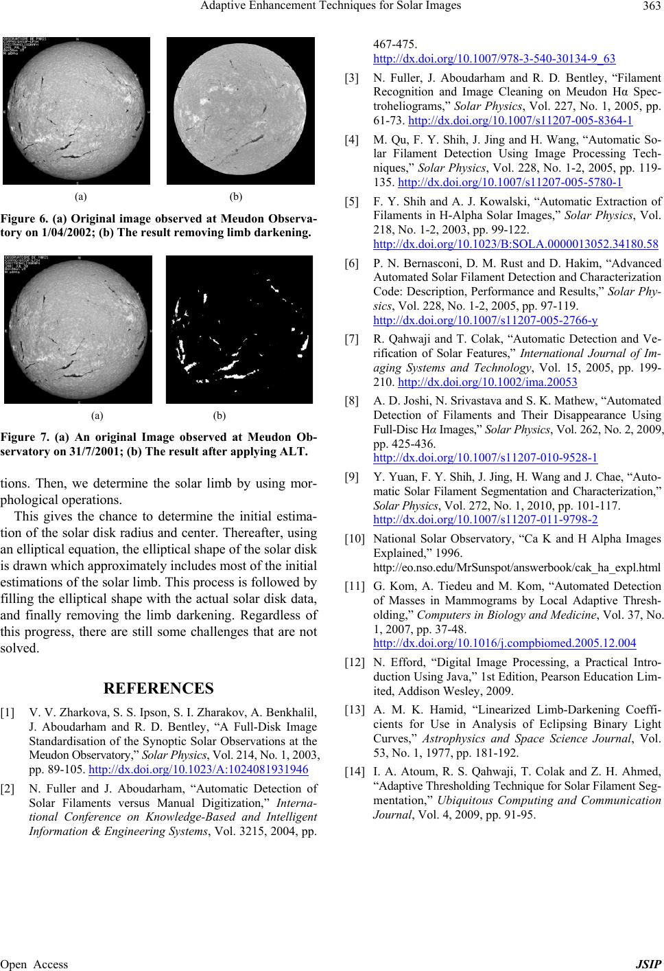 Adaptive Enhancement Techniques for Solar Images Open Access JSIP 363 (a) (b) Figure 6. (a) Original image observed at Meudon Observa- tory on 1/04/2002; (b) The result removing limb darkening. (a) (b) Figure 7. (a) An original Image observed at Meudon Ob- servatory on 31/7/2001; (b) The result after applying ALT. tions. Then, we determine the solar limb by using mor- phological operations. This gives the chance to determine the initial estima- tion of the solar disk radius and center. Thereafter, using an elliptical equation, the elliptical shape of the solar disk is drawn which approximately includes most of the initial estimations of the solar limb. This process is followed by filling the elliptical shape with the actual solar disk data, and finally removing the limb darkening. Regardless of this progress, there are still some challenges that are not solved. REFERENCES [1] V. V. Zharkova, S. S. Ipson, S. I. Zharakov, A. Benkhalil, J. Aboudarham and R. D. Bentley, “A Full-Disk Image Standardisation of the Synoptic Solar Observations at the Meudon Observatory,” Solar Physics, Vol. 214, No. 1, 2003, pp. 89-105. http://dx.doi.org/10.1023/A:1024081931946 [2] N. Fuller and J. Aboudarham, “Automatic Detection of Solar Filaments versus Manual Digitization,” Interna- tional Conference on Knowledge-Based and Intelligent Information & Engineering Systems, Vol. 3215, 2004, pp. 467-475. http://dx.doi.org/10.1007/978-3-540-30134-9_63 [3] N. Fuller, J. Aboudarham and R. D. Bentley, “Filament Recognition and Image Cleaning on Meudon Hα Spec- troheliograms,” Solar Physics, Vol. 227, No. 1, 2005, pp. 61-73. http://dx.doi.org/10.1007/s11207-005-8364-1 [4] M. Qu, F. Y. Shih, J. Jing and H. Wang, “Automatic So- lar Filament Detection Using Image Processing Tech- niques,” Solar Physics, Vol. 228, No. 1-2, 2005, pp. 119- 135. http://dx.doi.org/10.1007/s11207-005-5780-1 [5] F. Y. Shih and A. J. Kowalski, “Automatic Extraction of Filaments in H-Alpha Solar Images,” Solar Physics, Vol. 218, No. 1-2, 2003, pp. 99-122. http://dx.doi.org/10.1023/B:SOLA.0000013052.34180.58 [6] P. N. Bernasconi, D. M. Rust and D. Hakim, “Advanced Automated Solar Filament Detection and Characterization Code: Description, Performance and Results,” Solar Phy- sics, Vol. 228, No. 1-2, 2005, pp. 97-119. http://dx.doi.org/10.1007/s11207-005-2766-y [7] R. Qahwaji and T. Colak, “Automatic Detection and Ve- rification of Solar Features,” International Journal of Im- aging Systems and Technology, Vol. 15, 2005, pp. 199- 210. http://dx.doi.org/10.1002/ima.20053 [8] A. D. Joshi, N. Srivastava and S. K. Mathew, “Automated Detection of Filaments and Their Disappearance Using Full-Disc Hα Images,” Solar Physics, Vol. 262, No. 2, 2009, pp. 425-436. http://dx.doi.org/10.1007/s11207-010-9528-1 [9] Y. Yuan, F. Y. Shih, J. Jing, H. Wang and J. Chae, “Auto- matic Solar Filament Segmentation and Characterization,” Solar Physics, Vol. 272, No. 1, 2010, pp. 101-117. http://dx.doi.org/10.1007/s11207-011-9798-2 [10] National Solar Observatory, “Ca K and H Alpha Images Explained,” 1996. http://eo.nso.edu/MrSunspot/answerbook/cak_ha_expl.html [11] G. Kom, A. Tiedeu and M. Kom, “Automated Detection of Masses in Mammograms by Local Adaptive Thresh- olding,” Computers in Biology and Medicine, Vol. 37, No. 1, 2007, pp. 37-48. http://dx.doi.org/10.1016/j.compbiomed.2005.12.004 [12] N. Efford, “Digital Image Processing, a Practical Intro- duction Using Java,” 1st Edition, Pearson Education Lim- ited, Addison Wesley, 2009. [13] A. M. K. Hamid, “Linearized Limb-Darkening Coeffi- cients for Use in Analysis of Eclipsing Binary Light Curves,” Astrophysics and Space Science Journal, Vol. 53, No. 1, 1977, pp. 181-192. [14] I. A. Atoum, R. S. Qahwaji, T. Colak and Z. H. Ahmed, “Adaptive Thresholding Technique for Solar Filament Seg- mentation,” Ubiquitous Computing and Communication Journal, Vol. 4, 2009, pp. 91-95. |