

Paper Menu >>
Journal Menu >>
 Journal of Surface Engineered Materials and Advanced Technology, 2013, 3, 257-261 http://dx.doi.org/10.4236/jsemat.2013.34034 Published Online October 2013 (http://www.scirp.org/journal/jsemat) Dynamic Impact Absorption Behavi our of Glass Coa ted with Carbon Nanotubes Prashant Jindal1*, Meenakshi Goyal2, Navin Kumar3 1University Institute of Engineering & Technology, Panjab University, Chandigarh, India; 2University Institute of Chemical Engi- neering & Technology, Panjab University, Chandigarh, India; 3Indian Institute of Technology, Roopnagar, Punjab, India. Email: *[email protected] Received July 3rd, 2013; revised August 5th, 2013; accepted September 1st, 2013 Copyright © 2013 Prashant Jindal et al. This is an open access article distributed under the Creative Commons Attribution License, which permits unrestricted use, distribution, and reproduction in any medium, provided the original work is properly cited. ABSTRACT Boro-silicate glass samples were coated with chemically treated multi-walled carbon nanotubes (MWCNTs) to study the resistance offered by the coatings under the high strain rate impact. Impact testing of these glass samples was per- formed on Split Hopkinson Pressure Bar (SHPB), where strain rates were varied from 500/s to 3300/s. However, the comparisons were limited to samples subjected to a strain rate of 2300/s to 3000/s so that the effect of only variable deposits of coatings on the stress-strain behavior of glass can be studied. Variable deposits (0.1 mg to 0.8 mg) of MWCNTs were coated uniformly on glass samples having a disc shape with a fixed surface area (79 mm2) to observe the effect of the coating on the impact absorption capacity of glass. It was observed that the small thickness of about 25 µm formed due to the fact that 0.2 mg of MWCNTs deposit spread over the surface increased the impact absorption ca- pacity of the glass pieces by nearly 70%. However, beyond this amount when the deposit was increased to 0.4 mg, the coating thickness got doubled to nearly 49 µm and this led to a fall in absorption capacity which remained static till 0.8 mg deposit. However, even this decrease in capacity was able to absorb 30% more impact than offered by pure glass sample. Keywords: Glass Coatings; Impact Behaviour; Strength; Mechanical Properties 1. Introduction Over the years, impacting resistant materials has been ex- tensively studied using composites that comprise of light weight base matrix and strong filler materials. These ma- terials are tested under extreme impact and static loading conditions so that they can be used for various applica- tions like bullet-proof shields, jackets, resistant surfaces, shock and impact absorbers etc. [1,2]. Apart from fabricating stress resistant materials in the form of composites, absorber coatings also become im- portant when it comes to preserving the basic equipment and acting as a protective coat. These coatings can be sacrificed to protect the base material also. It becomes imperative that such coatings are their light weight so that their own weight does not affect the overall utility of the basic equipment. One of the most useful equipments for studying mate- rial behavior under impact loading is Split Hopkinson Pressure Bar (SHPB). Stress-strain behavior of the spe- cimen when subjected to impact or dynamic loading is obtained when the specimen is subjected to a strain rate of 100 to 10,000/s. The SHPB apparatus consists of two long slender bars namely, an input bar and an output bar that sandwich a short specimen between them. Whenever any load is ap- plied on one end, the sandwiched specimen undergoes very high compression loading. A block diagram of a ty- pical SHPB is shown in Figure 1. The details of working of Split Hopkinson bar set up are widely available in literature [3]. It is basically based upon the measurement of wave signal which is generated by the input and output bars due to high strain rate load- ing. The waves are a measure of strains which are cali- brated to find stress and strain in the specimen and in an earlier work. Impact loading using SHPB on carbon na- notube-polycarbonate composites was also studied [4]. To the best of our knowledge, most of the dynamic and quasi-static strength related work has been done on composite structures [4-9]. Static properties like elastic modulus, indentation pressure and fracture toughness of coatings on glass have been studied by Malzbender et al. [10,11]. In these studies, the composition of the coat- *Corresponding author. Copyright © 2013 SciRes. JSEMAT 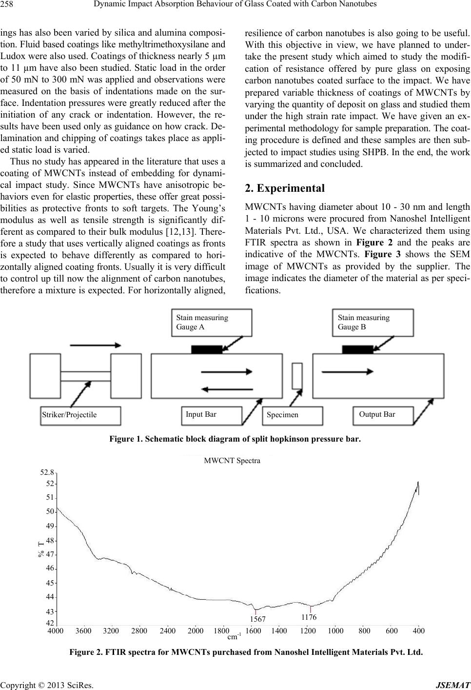 Dynamic Impact Absorption Behaviour of Glass Coated with Carbon Nanotubes 258 ings has also been varied by silica and alumina composi- tion. Fluid based coatings like methyltrimethoxysilane and Ludox were also used. Coatings of thickness nearly 5 µm to 11 µm have also been studied. Static load in the order of 50 mN to 300 mN was applied and observations were measured on the basis of indentations made on the sur- face. Indentation pressures were greatly reduced after the initiation of any crack or indentation. However, the re- sults have been used only as guidance on how crack. De- lamination and chipping of coatings takes place as appli- ed static load is varied. Thus no study has appeared in the literature that uses a coating of MWCNTs instead of embedding for dynami- cal impact study. Since MWCNTs have anisotropic be- haviors even for elastic properties, these offer great possi- bilities as protective fronts to soft targets. The Young’s modulus as well as tensile strength is significantly dif- ferent as compared to their bulk modulus [12,13]. There- fore a study that uses vertically aligned coatings as fronts is expected to behave differently as compared to hori- zontally aligned coating fronts. Usually it is very difficult to control up till now the alignment of carbon nanotubes, therefore a mixture is expected. For horizontally aligned, resilience of carbon nanotubes is also going to be useful. With this objective in view, we have planned to under- take the present study which aimed to study the modifi- cation of resistance offered by pure glass on exposing carbon nanotubes coated surface to the impact. We have prepared variable thickness of coatings of MWCNTs by varying the quantity of deposit on glass and studied them under the high strain rate impact. We have given an ex- perimental methodology for sample preparation. The coat- ing procedure is defined and these samples are then sub- jected to impact studies using SHPB. In the end, the work is summarized and concluded. 2. Experimental MWCNTs having diameter about 10 - 30 nm and length 1 - 10 microns were procured from Nanoshel Intelligent Materials Pvt. Ltd., USA. We characterized them using FTIR spectra as shown in Figure 2 and the peaks are indicative of the MWCNTs. Figure 3 shows the SEM image of MWCNTs as provided by the supplier. The image indicates the diameter of the material as per speci- fications. Stain measuring Gauge A Stain measuring Gauge B Input Bar Output Bar Striker/Projectile Specimen Figure 1. Schematic block diagra m of split hopkinson pressure bar. MWCNT Spectra 1567 117 6 400600 800 10001200140020002400 2800 32003600 4000 cm -1 16001800 42 43 44 45 46 47 48 49 50 51 52 52.8 % T Figure 2. FTIR spectra for MWCNTs purchased from Nanoshel Intelligent Materials Pvt. Ltd. Copyright © 2013 SciRes. JSEMAT 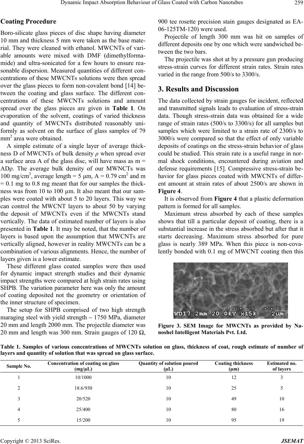 Dynamic Impact Absorption Behaviour of Glass Coated with Carbon Nanotubes 259 Coating Procedure Boro-silicate glass pieces of disc shape having diameter 10 mm and thickness 5 mm were taken as the base mate- rial. They were cleaned with ethanol. MWCNTs of vari- able amounts were mixed with DMF (dimethylforma- mide) and ultra-sonicated for a few hours to ensure rea- sonable dispersion. Measured quantities of different con- centrations of these MWCNTs solutions were then spread over the glass pieces to form non-covalent bond [14] be- tween the coating and glass surface. The different con- centrations of these MWCNTs solutions and amount spread over the glass pieces are given in Table 1. On evaporation of the solvent, coatings of varied thickness and quantity of MWCNTs distributed reasonably uni- formly as solvent on the surface of glass samples of 79 mm2 area were obtained. A simple estimate of a single layer of average thick- ness D of MWCNTs of bulk density ρ when spread over a surface area A of the glass disc, will have mass as m = ADρ. The average bulk density of our MWNCTs was 100 mg/cm3, average length = 5 μm, A = 0.79 cm2 and m = 0.1 mg to 0.8 mg meant that for our samples the thick- ness was from 10 to 100 µm. It also meant that our sam- ples were coated with about 5 to 20 layers. This way we can control the MWCNT layers to about 50 by varying the deposit of MWCNTs even if the MWCNTs stand vertically. The data of estimated number of layers is also presented in Ta b le 1 . It may be noted, that the number of layers is based upon the assumption that MWCNTs are vertically aligned, however in reality MWCNTs can be a combination of various alignments. Hence, the number of layers given is a lower estimate. These different glass coated samples were then used for dynamic impact strength studies and their dynamic impact strengths were compared at high strain rates using SHPB. The variation parameter here was only the amount of coating deposited not the geometry or orientation of the inner structure of specimen. The setup for SHPB comprised of two high strength maraging steel with yield strength ~ 1750 MPa, diameter 20 mm and length 2000 mm. The projectile diameter was 20 mm and length was 300 mm. Strain gauges of 120 Ω, 900 tee rosette precision stain gauges designated as EA- 06-125TM-120) were used. Projectile of length 300 mm was hit on samples of different deposits one by one which were sandwiched be- tween the two bars. The projectile was shot at by a pressure gun producing stress-strain curves for different strain rates. Strain rates varied in the range from 500/s to 3300/s. 3. Results and Discussion The data collected by strain gauges for incident, reflected and transmitted signals leads to evaluation of stress-strain data. Though stress-strain data was obtained for a wide range of strain rates (500/s to 3300/s) for all samples but samples which were limited to a strain rate of 2300/s to 3000/s were compared so that the effect of only variable deposits of coatings on the stress-strain behavior of glass could be studied. This strain rate is a useful range in nor- mal shock conditions, encountered during aviation and defense requirements [15]. Compressive stress-strain be- havior for glass pieces coated with MWCNTs of differ- ent amount at strain rates of about 2500/s are shown in Figure 4. It is observed from Figure 4 that a plastic deformation pattern is formed for all samples. Maximum stress absorbed by each of these samples shows that till a particular deposit of coating, there is a substantial increase in the stress absorbed but after that it starts decreasing. Maximum stress absorbed for pure glass is nearly 389 MPa. When this piece is non-cova- lently bonded with 0.1 mg of MWCNT coating then this Figure 3. SEM Image for MWCNTs as provided by Na- noshel Intelligent Materials Pvt. Ltd. Table 1. Samples of various concentrations of MWCNTs solution on glass, thickness of coat, rough estimate of number of layers and quantity of solution that was spread on glass surface. Sample No. Concentration of coating on glass (mg/µL) Quantity of solution poured (µL) Coating thickness (µm) Estimated no. of layers 1 10/1000 10 12 3 2 18.6/930 10 25 5 3 20/520 10 49 10 4 25/400 10 80 16 5 15/200 10 95 19 Copyright © 2013 SciRes. JSEMAT 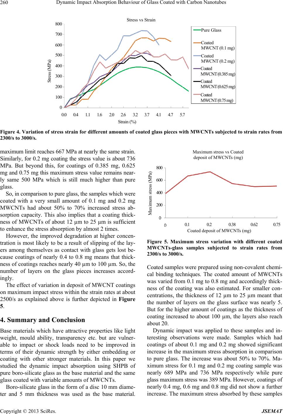 Dynamic Impact Absorption Behaviour of Glass Coated with Carbon Nanotubes 260 Stress vs Strain Pure Glass Coated MWCNT (0.1 mg) Coated MWCNT (0.2 mg) Coated MWCNT (0.385 mg) Coated MWCNT (0.625 mg) 0.0 0.4 1.1 1.6 2.02.63.23.74.14.7 5.7 Coated MWCNT (0.75 mg) Strain (%) 0 100 200 300 400 500 600 700 800 Stress (MPa) Figure 4. Variation of stress strain for different amounts of coated glass pieces with MWCNTs subjected to strain rates from 2300/s to 3000/s. maximum limit reaches 667 MPa at nearly the same strain. Similarly, for 0.2 mg coating the stress value is about 736 MPa. But beyond this, for coatings of 0.385 mg, 0.625 mg and 0.75 mg this maximum stress value remains near- ly same 500 MPa which is still much higher than pure glass. So, in comparison to pure glass, the samples which were coated with a very small amount of 0.1 mg and 0.2 mg MWCNTs had about 50% to 70% increased stress ab- sorption capacity. This also implies that a coating thick- ness of MWCNTs of about 12 µm to 25 µm is sufficient to enhance the stress absorption by almost 2 times. However, the improved degradation at higher concen- tration is most likely to be a result of slipping of the lay- ers among themselves as contact with glass gets lost be- cause coatings of nearly 0.4 to 0.8 mg means that thick- ness of coatings reaches nearly 40 µm to 100 µm. So, the number of layers on the glass pieces increases accord- ingly. The effect of variation in deposit of MWCNT coatings on maximum impact stress within the strain rates at about 2500/s as explained above is further depicted in Figure 5. 4. Summary and Conclusion Base materials which have attractive properties like light weight, mould ability, transparency etc. but are vulner- able to impact or shock loads need to be improved in terms of their dynamic strength by either embedding or coating with other stronger materials. In this paper we studied the dynamic impact absorption using SHPB of pure boro-silicate glass as the base material and the same glass coated with variable amounts of MWCNTs. Boro-silicate glass in the form of a disc 10 mm diame- ter and 5 mm thickness was used as the base material. Maximum stress vs Coated deposit of MWCNTs (mg) 20 0 Max i mum stress ( MPa ) 0.1 0.2 0.38 0.620.75 Coated deposit of MWCNTs (mg) 40 0 60 0 80 0 Figure 5. Maximum stress variation with different coated MWCNTs-glass samples subjected to strain rates from 2300/s to 3000/s. Coated samples were prepared using non-covalent chemi- cal binding techniques. The coated amount of MWCNTs was varied from 0.1 mg to 0.8 mg and accordingly thick- ness of the coating was also estimated. For smaller con- centrations, the thickness of 12 µm to 25 µm meant that the number of layers on the glass surface was nearly 5. But for the higher amount of coatings as the thickness of coating increased to about 100 µm, the layers also reach about 20. Dynamic impact was applied to these samples and in- teresting observations were made. Samples which had coatings of about 0.1 mg and 0.2 mg showed significant increase in the maximum stress absorption in comparison to pure glass. The increase was about 50% to 70%. Ma- ximum stress for 0.1 mg and 0.2 mg coating sample was nearly 689 MPa and 736 MPa respectively while pure glass maximum stress was 389 MPa. However, coatings of nearly 0.4 mg, 0.6 mg and 0.8 mg did not show a further increase. The maximum stress absorbed by these samples Copyright © 2013 SciRes. JSEMAT  Dynamic Impact Absorption Behaviour of Glass Coated with Carbon Nanotubes 261 was nearly 500 MPa, which was still about 30% higher than pure glass but much less than 0.1 mg and 0.2 mg. The reason for this reduction can be the increased thick- ness of coating that comprises of multiple layers of MWCNTs. As layers of coatings increase, there is slipping of these layers from the glass surface and amongst the layers themselves. As a result, the coatings slip away from the base glass surface and fail to offer higher resistance to impact. On the basis of the results obtained in this work, it seems safe to conclude that coating by small concentra- tions of MWCNT improves the dynamic impact strength of glass. It not only helps modify glass strength, but also is a useful impact stress sensor. In fact, a stacking of multiple coated glass samples can be used to absorb desired im- pact as well as sensing unit for such impacts. As the glass piece was covered with minor amounts of MWCNTs, the transparency loss was not significant. 5. Acknowledgements Prashant Jindal gratefully acknowledges financial sup- port from the Defence Research Organization (DRDO) for a research project (No. ARMREB/DSW/2011/129). He also acknowledges the Director, TBRL and the whole team of Gun Group for extending their lab facilities. Gui- dance provided by Biomoluecular Electronics and Nano- technology Division (BEND), at Central Scientific Instru- ments Organisation (CSIO), Chandigarh is also acknowl- edged. He is also grateful to Mr. Hitesh Sharma from Ac- curate Optics, Chandigarh for assistance in providing base material. Dr. Rajesh Kumar, UIET, Panjab University, Chandigarh assistance is also acknowledged. REFERENCES [1] J. N. Coleman, U. Khan, W. J. Blau and Y. K. Gun’ko, “Small but Strong: A Review of the Mechanical Proper- ties of Carbon Nanotube-Polymer Composites,” Carbon, Vol. 44, No. 9, 2006, pp. 1624-1652. http://dx.doi.org/10.1016/j.carbon.2006.02.038 [2] P. Raju Mantena, Alexander H. D. Cheng, Ahmed Al-Os- taz and A. M. Rajendran, “Blast and Impact Resistant Com- posite Structures for Navy Ships Composite Structures and Nano-Engineering Research” Proceedings of the 2008 ONR Solid Mechanics Program—Marine Composites and Sand- wich Structures, University of Maryland, Adelphi, 2009, pp. 417-426. [3] H. Kolsky, “An Investigation of the Mechanical Proper- ties of Materials at Very High Rates of Loading,” Pro- ceedings of the Royal Society of London, London, B62, 1949, pp. 676-700 [4] P. Jindal, S. Pande, P. Sharma, V. Mangla, A. Chaudhury, Deepak Patel, B. P. Singh, R. B. Mathur and M. Goyal, “High Strain Rate Behavior of Multi-Walled Carbon Na- notubes-Polycarbonate Composites,” Composites Part B: Engineering, Vol. 45, No. 1, 2013, pp. 417-422. http://dx.doi.org/10.1016/j.compositesb.2012.06.018 [5] N. K. Naik and Y. Perla, “Mechanical Behaviour of Acry- lic under High Strain Rate Tensile Loading,” Polymer Testing, Vol. 27, No. 4, 2008, pp. 504-512. http://dx.doi.org/10.1016/j.polymertesting.2008.02.005 [6] A. Jadhav, E. Woldesenbet and S.-S. Pang, “High Strain Rate Properties of Balanced Angle-Ply Graphite/Epoxy Composites,” Composites: Part B, Vol. 34, No. 4, 2003, pp. 339-346. http://dx.doi.org/10.1016/S1359-8368(03)00003-9 [7] W. Chen, F. Lu and M. Cheng, “Tension and Compres- sion Tests of Two Polymers under Quasistatic and Dyna- mic Loading,” Polymer Testing, Vol. 21, No. 2, 2002, pp. 113-121. http://dx.doi.org/10.1016/S0142-9418(01)00055-1 [8] R. B. Mathur, S. Pande, B. P. Singh and T. L. Dhami, “Elec- trical and Mechanical Properties of Multi-Walled Carbon Nanotubes Reinforced PMMA and PS Composites,” Po- lymer Composites, Vol. 29, No. 7, 2008, pp. 717-727. http://dx.doi.org/10.1002/pc.20449 [9] Y. H. Xu, Q. F. Li, D. Sun, W. N. Zhang and G.-X. Chen, “A Strategy to Functionalize the Carbon Nanotubes and the Nanocomposites Based on Poly(L-lactide),” Indus- trial & Engineering Chemistry Research, Vol. 51, No. 42, 2012, pp. 13648-13654. http://dx.doi.org/10.1021/ie300989w [10] J. Malzbender, G. de With and J. M. J. den Toonder, “Elastic Modulus, Indentation Pressure and Fracture Tough- ness of Hybrid Coatings on Glass,” Thin Solid Films, Vol. 366, No. 1-2, 2000, pp. 139-149. http://dx.doi.org/10.1016/S0040-6090(00)00656-8 [11] J. Malzbender and G. de With, “Energy Dissipation, Frac- ture Toughness and the Indentation Load-Displacement Curve for Coated Materials,” Surface and Coatings Tech- nology, Vol. 135, No. 1, 2000, pp. 60-68. http://dx.doi.org/10.1016/S0257-8972(00)00906-3 [12] R. S. Ruoff, D. Qian and W. K. Liu, “Mechanical Proper- ties of Carbon Nanotubes: Theoretical Predictions and Ex- perimental Measurements,” C. R. Physique, Vol. 4, No. 9, 2003, pp. 993-1008. http://dx.doi.org/10.1016/j.crhy.2003.08.001 [13] A. Sears and R. C. Batra, “Macroscopic Properties of Car- bon Nanotubes from Molecular-Mechanics Simulations,” Physical Review B, Vol. 69, 2004, Article ID: 235406. [14] Ma, A. Lu, J. Yang, S. H. Ka and M. Ng, “Quantitative Non-Covalent Functionalization of Carbon Nanotubes,” Journal of Cluster Science, Vol. 17, No. 4, 2006, pp. 599- 608. http://dx.doi.org/10.1007/s10876-006-0076-7 [15] Mostafa Shazly, David Nathenson and Vikas Prakash, “Mo- delling of High Strain Rate Deformation, Fracture and Impact Behavior of Advances Gas Turbine Engine Mate- rials at Low and Elevated Temperatures,” 2003, NASA CR-2003-212194. Copyright © 2013 SciRes. JSEMAT |