

Paper Menu >>
Journal Menu >>
 Journal of Software Engineering and Applications, 2013, 6, 526-532 http://dx.doi.org/10.4236/jsea.2013.610063 Published Online October 2013 (http://www.scirp.org/journal/jsea) Intelligent System Design for Stator Windings Faults Diagnosis: Suitable for Maintenance Work Lane M. Rabelo Baccarini, Vinícius S. Avelar, Valceres Vieira R. E. Silva, Gleison F. V. Amaral Department of Electrical Engineering, Federal University of São João del Rei, Praça Frei Orlando, Brasil. Email: [email protected] Received June 3rd, 2013; revised July 4th, 2013; accepted July 12th, 2013 Copyright © 2013 Lane M. Rabelo Baccarini et al. This is an open access article distributed under the Creative Commons Attribution License, which permits unrestricted use, distribution, and reproduction in any medium, provided the original work is properly cited. ABSTRACT The short circuit is a severe fault that occurs in the stator windings. Therefore, it is very important to diagnose this type of failure in its beginning before it causes unscheduled stop and the machine loss. In this context, the Support Vector Machine (SVM) is a tool of considerable importance for standard classification. From some training data, it can diag- nose whether or not there is a short circuit beginning, and which is important for predictive maintenance. This work proposes a technique for early detection of a short circuit between the turns aiming at its implementation in a real plant. The paper shows simulation and experimental results, and validates the proposed technique. Keywords: Fault Diagnosis; Support Vector Machines; Maintenance Work; Software Tool; Winding Short-Circuit 1. Introduction The induction machine is used in a wide variety of ap- plications to convert electrical energy into mechanical energy. There is no doubt that it is the most widely used machine in industry due to its robustness and low cost. However, the induction motors are very easy to be dam- aged during their operations. In some industrial processes, the induction motors are often installed in the hostile environment that may easily lead to the deterioration [1]. The production technique evolution grows up as fast as the productive capacity of industrial plants supported by the equipment improvement. The equipment’s life cycle requires high investments. Thus, the maintenance and operation schedule need to be safe, efficient and en- sure larger indexes of availability and security. Recently, there are a lot of methods used to detect sta- tor inter-turn short circuit in predictive maintenance. Nevertheless, many of them are expensive, ineffective or difficult to be implemented in real process. Another point is the fact that many processes are in continuous activi- ties or in aggressive environments; the motor requires monitoring since it drives a non-stop machine. It depends on a non-invasive way to detect faults, and no human is exposed directly to the machine in working condition [2, 3]. The induction machine stator windings are exposed to stress by different causes: thermal effects; mechanical vibrations; repetitive voltage pulses stresses under PWM inverter drives. Research shows that stator faults are re- sponsible for 36% of induction machine faults [4-6]. De- terioration of the induction machine three-phase insula- tion usually begins with short-circuit involving little turns of one phase. Fault current is approximately twice as high as the blocked rotor current. It causes local heat- ing and quickly spreads to other winding sections [7-10]. A short circuit is recognized as one of the most diffi- cult failures to be detected. Inter-turn short circuit faults that occur on the stator, start with a few inter-turns until reaching a more severe failure, such as phase-to-phase faults and phase-to-ground faults. It is known that the speed of the faults’ spread is fast, thereby justifying con- tinuous motor monitoring to detect the short circuit [11]. Thomson and Fenger (2001) analyzed short circuit between inter-turns of an induction machine in low volt- age working conditions [12]. According to the authors, even with a significant percentage of short-circuit (20% of turns in short circuit), the engine worked for 20 min- utes before complete breakdown. But researchers report that the impact of failure on the characteristics of the engine is small, which makes their detection difficult [13]. A variety of sensors could be used to collect meas- urement from the machine for the purpose of failure monitoring. These sensors measure stator voltages and currents, air-gap and external magnetic flux densities, Copyright © 2013 SciRes. JSEA 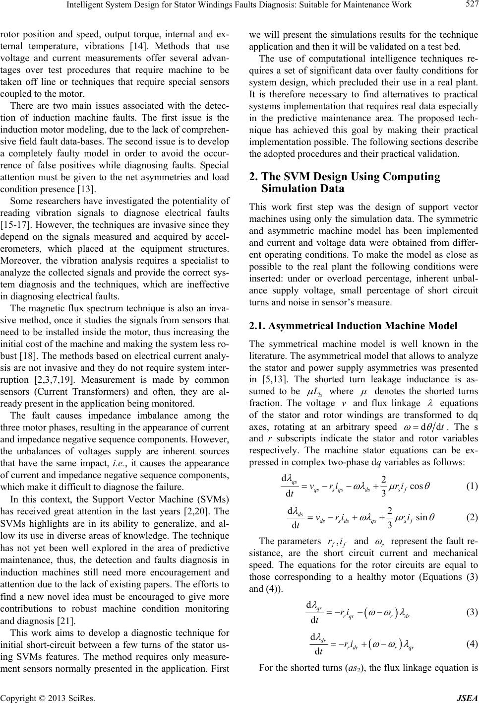 Intelligent System Design for Stator Windings Faults Diagnosis: Suitable for Maintenance Work 527 rotor position and speed, output torque, internal and ex- ternal temperature, vibrations [14]. Methods that use voltage and current measurements offer several advan- tages over test procedures that require machine to be taken off line or techniques that require special sensors coupled to the motor. There are two main issues associated with the detec- tion of induction machine faults. The first issue is the induction motor modeling, due to the lack of comprehen- sive field fault data-bases. The second issue is to develop a completely faulty model in order to avoid the occur- rence of false positives while diagnosing faults. Special attention must be given to the net asymmetries and load condition presence [13]. Some researchers have investigated the potentiality of reading vibration signals to diagnose electrical faults [15-17]. However, the techniques are invasive since they depend on the signals measured and acquired by accel- erometers, which placed at the equipment structures. Moreover, the vibration analysis requires a specialist to analyze the collected signals and provide the correct sys- tem diagnosis and the techniques, which are ineffective in diagnosing electrical faults. The magnetic flux spectrum technique is also an inva- sive method, once it studies the signals from sensors that need to be installed inside the motor, thus increasing the initial cost of the machine and making the system less ro- bust [18]. The methods based on electrical current analy- sis are not invasive and they do not require system inter- ruption [2,3,7,19]. Measurement is made by common sensors (Current Transformers) and often, they are al- ready present in the application being monitored. The fault causes impedance imbalance among the three motor phases, resulting in the appearance of current and impedance negative sequence components. However, the unbalances of voltages supply are inherent sources that have the same impact, i.e., it causes the appearance of current and impedance negative sequence components, which make it difficult to diagnose the failure. In this context, the Support Vector Machine (SVMs) has received great attention in the last years [2,20]. The SVMs highlights are in its ability to generalize, and al- low its use in diverse areas of knowledge. The technique has not yet been well explored in the area of predictive maintenance, thus, the detection and faults diagnosis in induction machines still need more encouragement and attention due to the lack of existing papers. The efforts to find a new novel idea must be encouraged to give more contributions to robust machine condition monitoring and diagnosis [21]. This work aims to develop a diagnostic technique for initial short-circuit between a few turns of the stator us- ing SVMs features. The method requires only measure- ment sensors normally presented in the application. First we will present the simulations results for the technique application and then it will be validated on a test bed. The use of computational intelligence techniques re- quires a set of significant data over faulty conditions for system design, which precluded their use in a real plant. It is therefore necessary to find alternatives to practical systems implementation that requires real data especially in the predictive maintenance area. The proposed tech- nique has achieved this goal by making their practical implementation possible. The following sections describe the adopted procedures and their practical validation. 2. The SVM Design Using Computing Simulation Data This work first step was the design of support vector machines using only the simulation data. The symmetric and asymmetric machine model has been implemented and current and voltage data were obtained from differ- ent operating conditions. To make the model as close as possible to the real plant the following conditions were inserted: under or overload percentage, inherent unbal- ance supply voltage, small percentage of short circuit turns and noise in sensor’s measure. 2.1. Asymmetrical Induction Machine Model The symmetrical machine model is well known in the literature. The asymmetrical model that allows to analyze the stator and power supply asymmetries was presented in [5,13]. The shorted turn leakage inductance is as- sumed to be ls L where denotes the shorted turns fraction. The voltage and flux linkage v equations of the stator and rotor windings are transformed to dq axes, rotating at an arbitrary speed ddt . The s and r subscripts indicate the stator and rotor variables respectively. The machine stator equations can be ex- pressed in complex two-phase dq variables as follows: d2cos d3 qs qss qsdssf vri ri t (1) d2sin d3 ds dss dsqssf vri ri t (2) The parameters , f f ri and r represent the fault re- sistance, are the short circuit current and mechanical speed. The equations for the rotor circuits are equal to those corresponding to a healthy motor (Equations (3) and (4)). d d qr rqrr dr ri t (3) d d dr rdrr qr ri t (4) For the shorted turns (as2), the flux linkage equation is Copyright © 2013 SciRes. JSEA 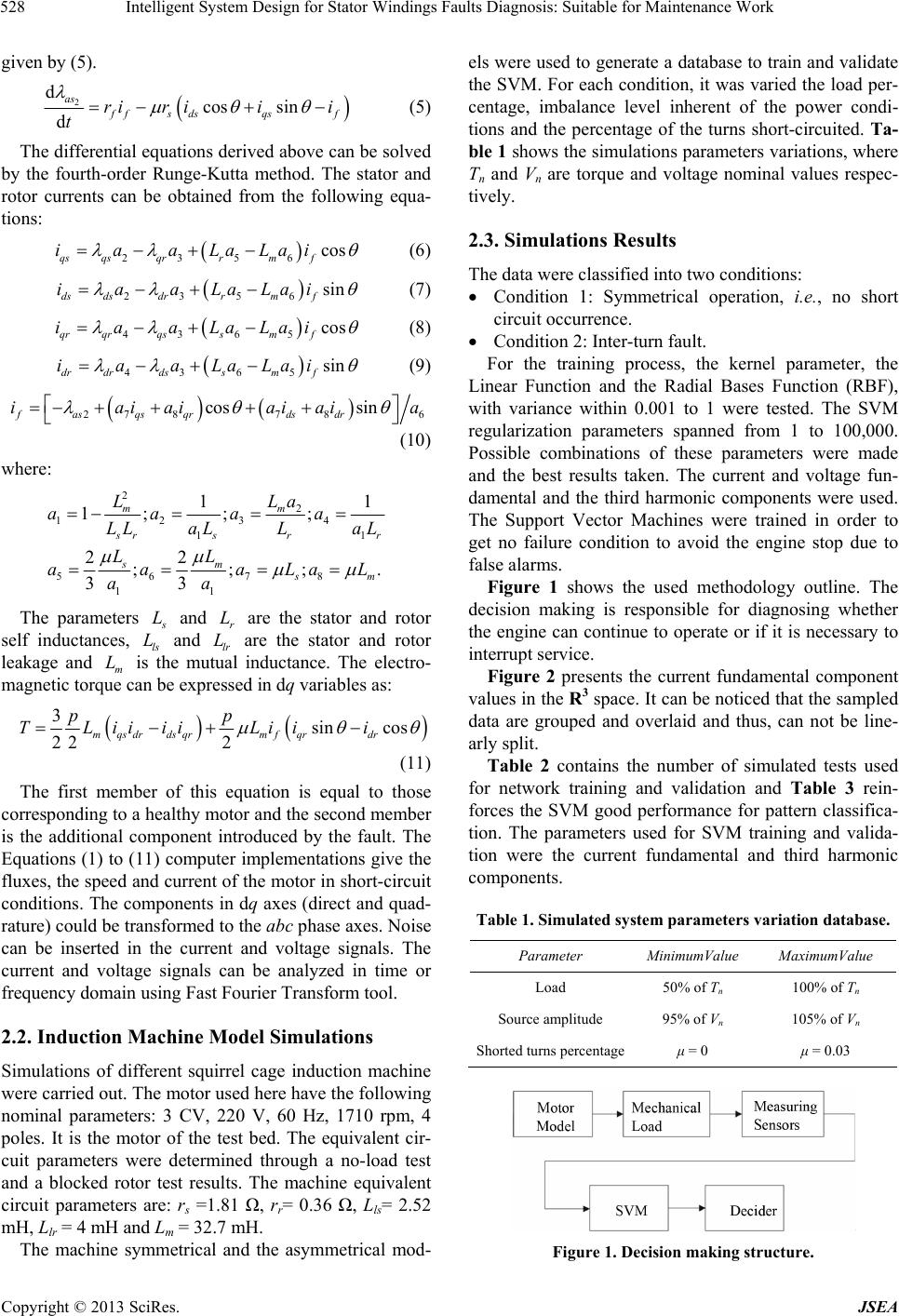 Intelligent System Design for Stator Windings Faults Diagnosis: Suitable for Maintenance Work 528 given by (5). 2 dcos sin d as f fs dsqsf rir iii t (5) The differential equations derived above can be solved by the fourth-order Runge-Kutta method. The stator and rotor currents can be obtained from the following equa- tions: 23 56 cos qs qsqrrmf iaaLaLai (6) 23 56 sin ds dsdrrmf iaaLaLai (7) 43 65 cos qrqr qss mf iaaLaLai (8) 43 65 sin drdr dss mf iaaLaLai (9) 27 87 8 cos sin fasqsqr dsdr iaiaiaiaia 6 (10) where: 2 2 1234 1 56 78 11 1 1; ;; 22 ;;; 33 mm 1 1 . s rsr sm r s m LLa aaaa LL aLLaL LL aa aLa aa L The parameters s L L and are the stator and rotor self inductances, ls and lr are the stator and rotor leakage and m is the mutual inductance. The electro- magnetic torque can be expressed in dq variables as: r L L L 3sin cos 22 2 mqsdrdsqrmf qrdr pp TLiiiiLii i (11) The first member of this equation is equal to those corresponding to a healthy motor and the second member is the additional component introduced by the fault. The Equations (1) to (11) computer implementations give the fluxes, the speed and current of the motor in short-circuit conditions. The components in dq axes (direct and quad- rature) could be transformed to the abc phase axes. Noise can be inserted in the current and voltage signals. The current and voltage signals can be analyzed in time or frequency domain using Fast Fourier Transform tool. 2.2. Induction Machine Model Simulations Simulations of different squirrel cage induction machine were carried out. The motor used here have the following nominal parameters: 3 CV, 220 V, 60 Hz, 1710 rpm, 4 poles. It is the motor of the test bed. The equivalent cir- cuit parameters were determined through a no-load test and a blocked rotor test results. The machine equivalent circuit parameters are: rs =1.81 Ω, rr= 0.36 Ω, Lls= 2.52 mH, Llr = 4 mH and Lm = 32.7 mH. The machine symmetrical and the asymmetrical mod- els were used to generate a database to train and validate the SVM. For each condition, it was varied the load per- centage, imbalance level inherent of the power condi- tions and the percentage of the turns short-circuited. Ta- ble 1 shows the simulations parameters variations, where Tn and Vn are torque and voltage nominal values respec- tively. 2.3. Simulations Results The data were classified into two conditions: Condition 1: Symmetrical operation, i.e., no short circuit occurrence. Condition 2: Inter-turn fault. For the training process, the kernel parameter, the Linear Function and the Radial Bases Function (RBF), with variance within 0.001 to 1 were tested. The SVM regularization parameters spanned from 1 to 100,000. Possible combinations of these parameters were made and the best results taken. The current and voltage fun- damental and the third harmonic components were used. The Support Vector Machines were trained in order to get no failure condition to avoid the engine stop due to false alarms. Figure 1 shows the used methodology outline. The decision making is responsible for diagnosing whether the engine can continue to operate or if it is necessary to interrupt service. Figure 2 presents the current fundamental component values in the R3 space. It can be noticed that the sampled data are grouped and overlaid and thus, can not be line- arly split. Table 2 contains the number of simulated tests used for network training and validation and Table 3 rein- forces the SVM good performance for pattern classifica- tion. The parameters used for SVM training and valida- tion were the current fundamental and third harmonic components. Table 1. Simulated system parameters variation database. Parameter MinimumValue MaximumValue Load 50% of Tn 100% of Tn Source amplitude 95% of Vn 105% of Vn Shorted turns percentageμ = 0 μ = 0.03 Figure 1. Decision making structure. Copyright © 2013 SciRes. JSEA 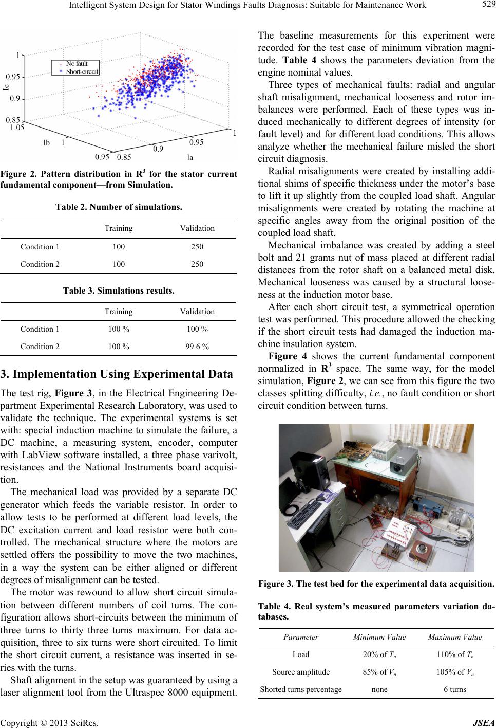 Intelligent System Design for Stator Windings Faults Diagnosis: Suitable for Maintenance Work 529 Figure 2. Pattern distribution in R3 for the stator current fundamental component—from Simulation. Table 2. Number of simulations. Training Validation Condition 1 100 250 Condition 2 100 250 Table 3. Simulations results. Training Validation Condition 1 100 % 100 % Condition 2 100 % 99.6 % 3. Implementation Using Experimental Data The test rig, Figure 3, in the Electrical Engineering De- partment Experimental Research Laboratory, was used to validate the technique. The experimental systems is set with: special induction machine to simulate the failure, a DC machine, a measuring system, encoder, computer with LabView software installed, a three phase varivolt, resistances and the National Instruments board acquisi- tion. The mechanical load was provided by a separate DC generator which feeds the variable resistor. In order to allow tests to be performed at different load levels, the DC excitation current and load resistor were both con- trolled. The mechanical structure where the motors are settled offers the possibility to move the two machines, in a way the system can be either aligned or different degrees of misalignment can be tested. The motor was rewound to allow short circuit simula- tion between different numbers of coil turns. The con- figuration allows short-circuits between the minimum of three turns to thirty three turns maximum. For data ac- quisition, three to six turns were short circuited. To limit the short circuit current, a resistance was inserted in se- ries with the turns. Shaft alignment in the setup was guaranteed by using a laser alignment tool from the Ultraspec 8000 equipment. The baseline measurements for this experiment were recorded for the test case of minimum vibration magni- tude. Table 4 shows the parameters deviation from the engine nominal values. Three types of mechanical faults: radial and angular shaft misalignment, mechanical looseness and rotor im- balances were performed. Each of these types was in- duced mechanically to different degrees of intensity (or fault level) and for different load conditions. This allows analyze whether the mechanical failure misled the short circuit diagnosis. Radial misalignments were created by installing addi- tional shims of specific thickness under the motor’s base to lift it up slightly from the coupled load shaft. Angular misalignments were created by rotating the machine at specific angles away from the original position of the coupled load shaft. Mechanical imbalance was created by adding a steel bolt and 21 grams nut of mass placed at different radial distances from the rotor shaft on a balanced metal disk. Mechanical looseness was caused by a structural loose- ness at the induction motor base. After each short circuit test, a symmetrical operation test was performed. This procedure allowed the checking if the short circuit tests had damaged the induction ma- chine insulation system. Figure 4 shows the current fundamental component normalized in R3 space. The same way, for the model simulation, Figure 2, we can see from this figure the two classes splitting difficulty, i.e., no fault condition or short circuit condition between turns. Figure 3. The test bed for the exper i mental data acquisition. Table 4. Real system’s measured parameters variation da- tabases. Parameter Minimum Value Maximum Value Load 20% of Tn 110% of Tn Source amplitude 85% of Vn 105% of Vn Shorted turns percentagenone 6 turns Copyright © 2013 SciRes. JSEA 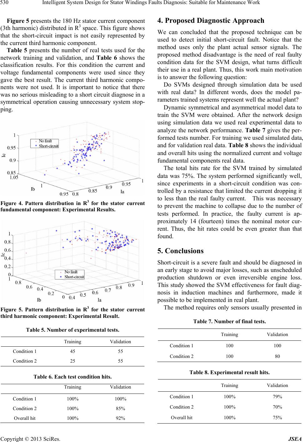 Intelligent System Design for Stator Windings Faults Diagnosis: Suitable for Maintenance Work 530 Figure 5 presents the 180 Hz stator current component (3th harmonic) distributed in R3 space. This figure shows that the short-circuit impact is not easily represented by the current third harmonic component. Table 5 presents the number of real tests used for the network training and validation, and Table 6 shows the classification results. For this condition the current and voltage fundamental components were used since they gave the best result. The current third harmonic compo- nents were not used. It is important to notice that there was no serious misleading to a short circuit diagnose in a symmetrical operation causing unnecessary system stop- ping. Figure 4. Pattern distribution in R3 for the stator current fundamental component: Experimental Re sults. Figure 5. Pattern distribution in R3 for the stator current third harmonic component: Experimental Result. Table 5. Number of experimental tests. Training Validation Condition 1 45 55 Condition 2 25 55 Table 6. Each test condition hits. Training Validation Condition 1 100% 100% Condition 2 100% 85% Overall hit 100% 92% 4. Proposed Diagnostic Approach We can concluded that the proposed technique can be used to detect initial short-circuit fault. Notice that the method uses only the plant actual sensor signals. The proposed method disadvantage is the need of real faulty condition data for the SVM design, what turns difficult their use in a real plant. Thus, this work main motivation is to answer the following question: Do SVMs designed through simulation data be used with real data? In different words, does the model pa- rameters trained systems represent well the actual plant? Dynamic symmetrical and asymmetrical model data to train the SVM were obtained. After the network design using simulation data we used real experimental data to analyze the network performance. Table 7 gives the per- formed tests number. For training we used simulated data, and for validation real data. Tab l e 8 shows the individual and overall hits using the normalized current and voltage fundamental components real data. The total hits rate for the SVM trained by simulated data was 75%. The system performed significantly well, since experiments in a short-circuit condition was con- trolled by a resistance that limited the current dropping it to less than the real faulty current. This was necessary to prevent the machine to collapse due to the number of tests performed. In practice, the faulty current is ap- proximately 14 (fourteen) times the nominal motor cur- rent. Thus, the hit rates could be even greater than that found. 5. Conclusions Short-circuit is a severe fault and should be diagnosed in an early stage to avoid major losses, such as unscheduled production shutdown or even irreversible engine loss. This study showed the SVM effectiveness for fault diag- nosis in induction machines and furthermore, made it possible to be implemented in real plant. The method requires only sensors usually presented in Table 7. Number of final tests. Training Validation Condition 1 100 100 Condition 2 100 80 Table 8. Experimental result hits. Training Validation Condition 1 100% 79% Condition 2 100% 70% Overall hit 100% 75% Copyright © 2013 SciRes. JSEA 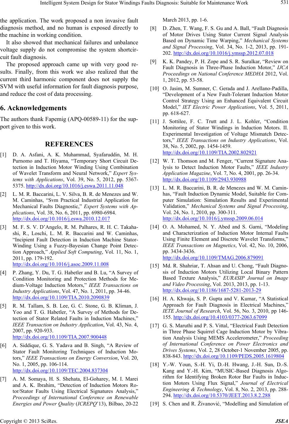 Intelligent System Design for Stator Windings Faults Diagnosis: Suitable for Maintenance Work 531 the application. The work proposed a non invasive fault diagnosis method, and no human is exposed directly to the machine in working condition. It also showed that mechanical failures and unbalance voltage supply do not compromise the system shortcir- cuit fault diagnosis. The proposed approach came up with very good re- sults. Finally, from this work we also realized that the current third harmonic component does not supply the SVM with useful information for fault diagnosis purpose, and reduce the cost of data processing. 6. Acknowledgements The authors thank Fapemig (APQ-00589-11) for the sup- port given to this work. REFERENCES [1] D. A. Asfani, A. K. Muhammad, Syafaruddin, M. H. Purnomo and T. Hiyama, “Temporary Short Circuit De- tection in Induction Motor Winding Using Combination of Wavelet Transform and Neural Network,” Expert Sys- tems with Applications, Vol. 39, No. 5, 2012, pp. 5367- 5375. http://dx.doi.org/10.1016/j.eswa.2011.11.048 [2] L. M. R. Baccarini, L. V. Silva, B. R. de Menezes and W. M. Caminhas, “Svm Practical Industrial Application for Mechanical Faults Diagnostic,” Expert Systems with Ap- plications, Vol. 38, No. 6, 2011, pp. 6980-6984. http://dx.doi.org/10.1016/j.eswa.2010.12.017 [3] M. F. S. V. D’Angelo, R. M. Palhares, R. H. C. Takaha- shi, R., Loschi, L. M. R. Baccarini and W. Caminhas, “Incipient Fault Detection in Induction Machine Stator- Winding Using a Fuzzy-Bayesian Change Point Detec- tion Approach,” Applied Soft Computing, Vol. 11, No. 1, 2011, pp. 179-192. http://dx.doi.org/10.1016/j.asoc.2009.11.008 [4] P. Zhang, Y. Du, T. G. Habetler and B. Lu, “A Survey of Condition Monitoring and Protection Methods for Me- dium-Voltage Induction Motors,” IEEE Transactions on Industry Applications, Vol. 47, No. 1, 2011, pp. 34-46. http://dx.doi.org/10.1109/TIA.2010.2090839 [5] R. M. Tallam, S. B. Lee, G. C. Stone, G. B. Kliman, J. Yoo and T. G. Habetler, “A Survey of Methods for De- tection of Stator Related Faults in Induction Machines,” IEEE Transaction on Industry Application, Vol. 43, No. 4, 2007, pp. 920-933. http://dx.doi.org/10.1109/TIA.2007.900448 [6] A. Siddique, G. S. Yadava and B. Singh, “A Review of Stator Fault Monitoring Techniques of Induction Mo- tors,” IEEE Transactions on Energy Conversion, Vol. 20, No. 1, 2005, pp. 106-114. http://dx.doi.org/10.1109/TEC.2004.837304 [7] A. M. Somaya, H. S. Shehata, El-Goharey, M. I. Marei and A. K. Ibrahim, “Detection of Induction Motors Ro- tor/Stator Faults Using Electrical Signatures Analysis,” Proceedings of International Conference on Renewable Energies and Power Quality (ICREPQ’13), Bilbao, 20-22 March 2013, pp. 1-6. [8] D. Zhen, T. Wang, F. S. Gu and A. Ball, “Fault Diagnosis of Motor Drives Using Stator Current Signal Analysis Based on Dynamic Time Warping,” Mechanical Systems and Signal Processing, Vol. 34, No. 1-2, 2013, pp. 191- 202. http://dx.doi.org/10.1016/j.ymssp.2012.07.018 [9] K. K. Pandey, P. H. Zope and S. R. Suralkar, “Review on Fault Diagnosis in Three-Phase Induction Motor,” IJCA Proceedings on National Conference MEDHA 2012, Vol. 1, 2012, pp. 53-58. [10] O. Jasim, M. Sumner, C. Gerada and J. Arellano-Padilla, “Development of a New Fault-Tolerant Induction Motor Control Strategy Using an Enhanced Equivalent Circuit Model,” IET Electric Power Applications, Vol. 5, 2011, pp. 618-627. [11] J. Sottilee, F. C. Trutt and J. L. Kohler, “Condition Monitoring of Stator Windings in Induction Motors. II. Experimental Investigation of Voltage Mismatch Detec- tors,” IEEE Transactions on Industry Applications, Vol. 38, No. 5, 2002, pp. 1454-1459. http://dx.doi.org/10.1109/TIA.2002.802921 [12] W. T. Thomson and M. Fenger, “Current Signature Ana- lysis to Detect Induction Motor Faults,” IEEE Industry Application Magazine, Vol. 7, No. 4, 2001, pp. 26-34. http://dx.doi.org/10.1109/2943.930988 [13] L. M. R. Baccarini, B. R. de Menezes and W. M. Camin- has, “Fault Induction Dynamic Model, Suitable for Com- puter Simulation: Simulation Results and Experimental Validation,” Mechanical Systems and Signal Processing, Vol. 24, No. 1, 2010, pp. 300-311. http://dx.doi.org/10.1016/j.ymssp.2009.06.014 [14] O. A. Mohamed, N. Y. Abed and S. Garni, “Modeling and Characterization of Induction Motor Internal Faults Using Finite Element and Discrete Wavelet Transforms,” IEEE Transactions on Magnetics, Vol. 42, No. 10, 2006, pp. 3434-3436. http://dx.doi.org/10.1109/TMAG.2006.879091 [15] Md. R. Shahriar, T. Ahsan and U. Chong, “Fault Diagno- sis of Induction Motors Utilizing Local Binary Pattern Based Texture Analysis,” EURASIP Journal on Image and Video Processing, Vol. 2013, 2013, pp. 1-13. http://dx.doi.org/10.1186/1687-5281-2013-29 [16] H. A. Khwaja, S. P. Gupta and V. Kumar, “A Statistical Approach for Fault Diagnosis in Electrical Machines,” IETE Journal of Research, Vol. 56, No. 3, 2010, pp 146- 155. http://dx.doi.org/10.4103/0377-2063.67099 [17] G. S. Maruthi and P. S. Vittal, “Electrical Fault Detection in Three Phase Squirrel Cage Induction Motor by Vibra- tion Analysis Using MEMS Accelerometer,” Proceeding of International Conference on Power Electronics and Drives Systems, Vol. 2, 28 October-1 November 2005, pp. 838-843. http://dx.doi.org/10.1109/PEDS.2005.1619804 [18] Y.-W. Youn, S.-H. Yi, D.-H. Hwang, J.-H. Sun, D.-S. Kang and Y.-H. Kim, “MUSIC-Based Diagnosis Algo- rithm for Identifying Broken Rotor Bar Faults in Induc- tion Motors Using Flux Signal,” Journal of Electrical Engineering & Technology, Vol. 8, No. 2, 2013, pp. 288- 294. http://dx.doi.org/10.5370/JEET.2013.8.2.288 [19] S. Chen and R. Živanović, “Modelling and Simulation of Copyright © 2013 SciRes. JSEA  Intelligent System Design for Stator Windings Faults Diagnosis: Suitable for Maintenance Work Copyright © 2013 SciRes. JSEA 532 Stator and Rotor Fault Conditions in Induction Machines for Testing Fault Diagnostic Techniques,” European Transactions on Electrical Power, Vol. 20, No. 5, 2010, pp. 611-629. http://dx.doi.org/10.1002/etep.342 [20] A. Widodo, B. S. Yang and T. Han, “Combination of Independent Component Analysis and Support Vector Machines for Intelligent Faults Diagnosis of Induction motors,” Expert Systems with Application, Vol. 32, No. 2, 2007, pp. 299-312. http://dx.doi.org/10.1016/j.eswa.2005.11.031 [21] A. Widodo and B. S. Yang. “Wavelet Support Vector Machine for Induction Machine Fault Diagnosis Based on Transient Current Signal,” Expert System with Applica- tion, Vol. 35, No. 1-2, 2008, pp. 307-316. http://dx.doi.org/10.1016/j.eswa.2007.06.018 |