

Paper Menu >>
Journal Menu >>
 Vol.3, No.1, 36-41 (2011) Natural Science http://dx.doi.org/10.4236/ns.2011.31004 Copyright © 2011 SciRes. OPEN ACCESS Investigation on the performance of DI-BSCCO superconducting electric motor Chin Kat Meng, Nasri A. Hamid*, Mohd. Yusri Abd. Rahman Department of Engineering Sciences & Mathematics, College of Engineering, Universiti Tenaga Nasional, Kajang, Selangor, Malay- sia; *Corresponding author:[email protected] Received 3 November 2010; revised 5 December 2010; accepted 8 December 2010. ABSTRACT Superconducting electrical devices have been developed in various fields especially in indus- trial energy over a decade. Superconducting motor is one of the electrical devices that at- tracted the attention of engineers and re- searchers from the universities and industries due to its distinctive energy efficiency. This paper describes the performance of supercon- ducting electric motor and its performance was compared with conventional copper electric motor. Direct current (DC) synchronous single- phase series motor has been chosen as the base for development of both motors. Two pro- totypes of electric motor fabricated using con- ventional copper coil and superconducting coil were developed with similar motor type, design, dimension, and features. The superconducting motor coil was wound using Bi-2223 (DI-BSCCO) Type H wires developed by Sumitomo Electric Industries Limited, Japan. A finite element analysis was performed to get a clear view on flux plots of the magnetic induction. Features of the superconducting motor and the special coil frame designed to protect the superconducting wire was also presented in this paper. In addi- tion, the torque performances for both types of motor were measured. The superconducting electric motor was found to consume lower power to produce the same output compared with the conventional copper-wound motor. Keywords: Superconductor; Magnetic flux; Finite Element Analysis; Electric Motor 1. INTRODUCTION Since the discovery of superconductivity in 1911 by Kamerlingh Onnes, the dream of creating highly effi- cient electric machine is getting closer to a reality. Su- perconducting materials are able to carry current with zero resistance and reduce power loss during the process of transmitting electricity [1]. This distinctive property of superconductor has seized the attention of many re- searches and a lot of studies have been carried out to produce superconducting wire with high stability. Fi- nally, long length superconducting wire has been suc- cessfully produced with a very reliable performance [2,3]. Superconducting devices such as magnetic reso- nance imaging (MRI) and superconducting quantum interference devices (SQUID) have been used in medi- cine and industry extensively. Several others electrical power devices such as motor, generator, fault current limiter and magnetic storage system have been devel- oped [4-6]. Superconductor required cooling process below the critical temperature, Tc which is also called as transition temperature to become zero resistance. The conventional low temperature superconductor operates at below 20 K, where cooling by liquid helium is re- quired. In 1986, researchers discovered high temperature superconductor where the critical temperature is higher than 77 K. Therefore, the use of cheaper refrigerant such as liquid nitrogen is sufficient to cool the superconduct- ing material and become superconductivity [7]. The distinctive properties of superconductor enable the development of high efficiency energy devices. It is believed that superconducting motor is able to reduce in size and minimize energy loss compared to the conven- tional copper-base motor [7,8]. In this work, a low power superconducting electric motor is fabricated and its performance was compared with a conventional elec- tric motor. All the specifications for both types of motor are similar except for the coils. The intended applica- tions of the motor are for driving industry devices such as pump and fan that can operate continuously at a con- stant speed. The features and performance of both types of motor were investigated. The simulation of the flux plot was also presented. 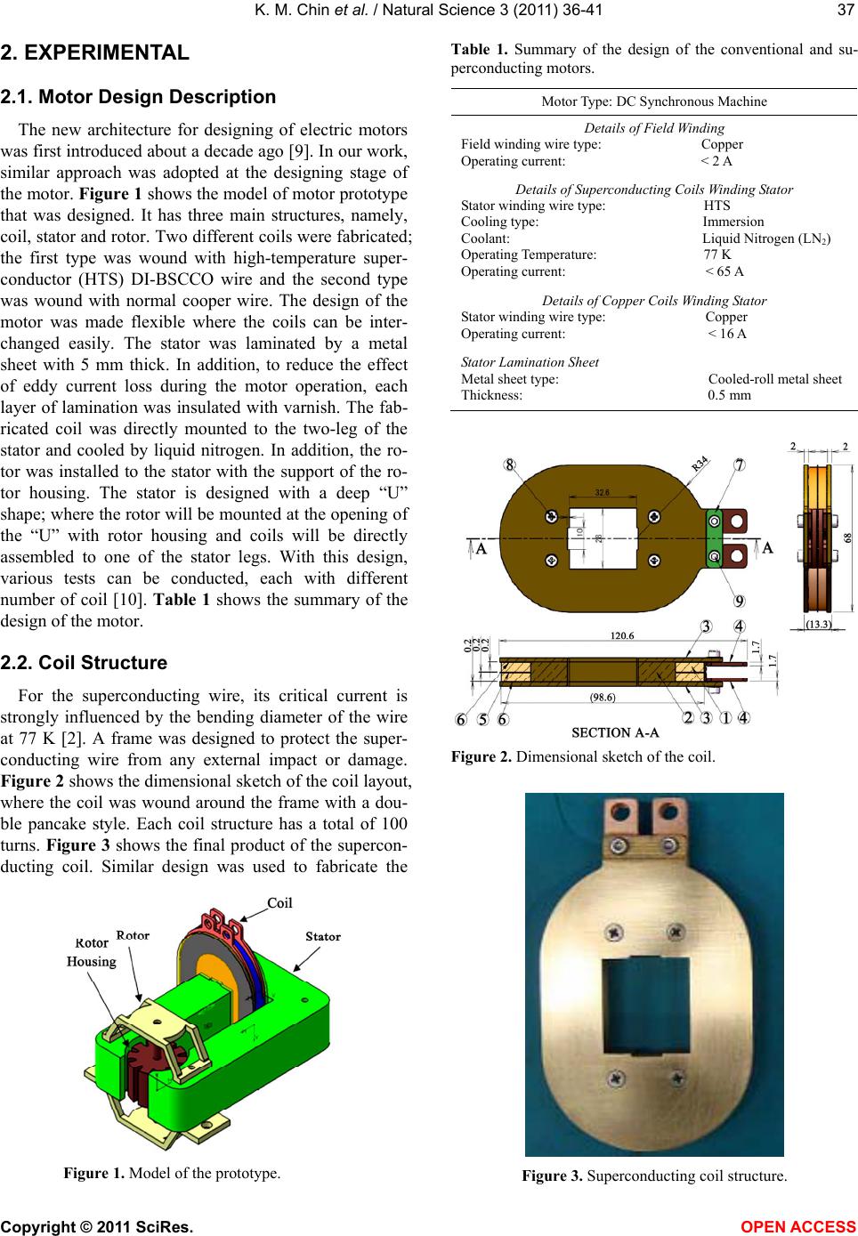 K. M. Chin et al. / Natural Science 3 (2011) 36-41 Copyright © 2011 SciRes. OPEN ACCESS 3737 2. EXPERIMENTAL 2.1. Motor Design Description The new architecture for designing of electric motors was first introduced about a decade ago [9]. In our work, similar approach was adopted at the designing stage of the motor. Figure 1 shows the model of motor prototype that was designed. It has three main structures, namely, coil, stator and rotor. Two different coils were fabricated; the first type was wound with high-temperature super- conductor (HTS) DI-BSCCO wire and the second type was wound with normal cooper wire. The design of the motor was made flexible where the coils can be inter- changed easily. The stator was laminated by a metal sheet with 5 mm thick. In addition, to reduce the effect of eddy current loss during the motor operation, each layer of lamination was insulated with varnish. The fab- ricated coil was directly mounted to the two-leg of the stator and cooled by liquid nitrogen. In addition, the ro- tor was installed to the stator with the support of the ro- tor housing. The stator is designed with a deep “U” shape; where the rotor will be mounted at the opening of the “U” with rotor housing and coils will be directly assembled to one of the stator legs. With this design, various tests can be conducted, each with different number of coil [10]. Table 1 shows the summary of the design of the motor. 2.2. Coil Structure For the superconducting wire, its critical current is strongly influenced by the bending diameter of the wire at 77 K [2]. A frame was designed to protect the super- conducting wire from any external impact or damage. Figure 2 shows the dimensional sketch of the coil layout, where the coil was wound around the frame with a dou- ble pancake style. Each coil structure has a total of 100 turns. Figure 3 shows the final product of the supercon- ducting coil. Similar design was used to fabricate the Figure 1. Model of the prototype. Table 1. Summary of the design of the conventional and su- perconducting motors. Motor Type: DC Synchronous Machine Details of Field Winding Field winding wire type: Copper Operating current: < 2 A Details of Superconducting Coils Winding Stator Stator winding wire type: HTS Cooling type: Immersion Coolant: Liquid Nitrogen (LN 2) Operating Temperature: 77 K Operating current: < 65 A Details of Copper Coils Winding Stator Stator winding wire type: Copper Operating current: < 16 A Stator Lamination Sheet Metal sheet type: Cooled-roll metal sheet Thickness: 0.5 mm Figure 2. Dimensional sketch of the coil. Figure 3. Superconducting coil structure.  K. M. Chin et al. / Natural Science 3 (2011) 36-41 Copyright © 2011 SciRes. OPEN ACCESS 38 conventional copper coil as shown in Figure 4. The conventional coil structure has exactly the same design and dimensions with the superconducting coil. Table 2 shows the materials and specifications for the superconducting coil and its components. Selection of the materials for the coil unit is important to ensure the effective distribution of magnetic flux. Ferromagnetic material must be avoided in the coil components to eliminate the suppression of magnetic flux [11]. In this design, brass which is a non-magnetic material was used in the construction of the frame and edge plate. 3. THEORY 3.1. Electromagnetic Theory Rotating machinery working principles are based on electromagnetic laws. One of the main laws is Ampere’s law which is defined as “the line integral of the magnetic field strength taken around any closed path is propor- tional to the total current flowing across any area, bounded by the path” [12]. Mathematically, the law is expressed by: H dlJ ds (1) where J is conduction current density, H is magnetic field intensity, dl is the differential length, ds is differen- tial surface enclosed by the closed path of length, and is integral over a closed loop or closed path. 3.2. Field Strength of Magnetic Circuit A magnetic field system comprises of N-turns coil wound on the ferromagnetic core. The coil carries a con- stant current, i through a uniform cross-sectional area, Ac of the core. When the current flows inside the conductor, magnetic field is generated inside the core and a mag- netic flux is confined to the ferromagnetic core. In the actual practice, a small portion of the flux will leak to the environment but this can be neglected due to its small percentage compared to the total flux. Therefore, the current through the enclosed path is expressed by: J ds Ni (2) where N is number of turn wound on the core and i is current inside conductor. From (1) and (2), the following relationship is obtained and is expressed by: H dl Ni (3) Figure 5 shows the equivalent magnetic circuit of the motor. Subscripts r, a, y, and c indicate “rotor”, “air- gap”, “york” and “cor e”, respectively. represents magnetic flux. Symbols c and r denote magnetic fluxes that are generated by the coil and the rotor, re- spectively. “R” indicates the reluctance inside the circuit. In this case, circuital law can be applied to this flux path, and thus from (3), the total current in the circuit shown in Figure 5 is expressed as: Figure 4. Conventional copper coil structure. Table 2. Specification of the superconducting coil and compo- nents. No.Item Material Specification 1 HTS coil Type H Double Pancake 100 turns 2 Frame Brass - 3 Edge Plate Brass - 4 Terminal Copper - 5 Separator GFRP Thickness 0.2 mm 6 Edge SeparatorGFRP Thickness 0.2 mm 7 Insulation PlateGFRP Thickness 0.2 mm 8 Screw Blot - M3 9 Screw - M3 *GFRP = Glass Fiber Reinforced Polymer r r c a R r R a R y R Figure 5. Equivalent magnetic circuit of the system.  K. M. Chin et al. / Natural Science 3 (2011) 36-41 Copyright © 2011 SciRes. OPEN ACCESS 3939 Ni HL (4) or 22 ccrryya ar r NiNiHLHLH L (5) 4. RESULTS AND DISCUSSIONS 4.1. Finite Element Analysis A finite element analysis was applied to investigate the behavior of the magnetic flux inside the motor. The analysis is very useful to verify an ideal magnetic circuit and to detect any error in the electrical connection, espe- cially for the DC machine. Another advantage of apply- ing finite element analysis before the actual testing is to avoid any short-circuit current between the motor com- ponents. Figure 6 shows the model of the motor which was constructed from the finite element analysis. The model was built with a full scale dimension. Figure 7 shows the magnetic flux path in the circuit. From the flux plot, it indicates that the flux loss was in the form of flux leakage and fringe effect. The simulated result shown in Figure 8 indicates that the flux density was inside the body of the motor. In the figure, it is ob- vious that a high flux density is in the area around the air-gap and the rotor. In contrast, the other parts of the motor do not show high flux density, indicating a low distribution of flux. The high flux density in the rotor and air-gap area is needed to establish a high force that enables the rotor to rotate. 4.2. Motor Assembly and Testing The lamination of metal sheet on the motor formed the stator. The superconducting coil was mounted on one leg of a stator. A rotor was then mounted on the rotor housing and the housing was attached to the stator. Thus, a complete superconducting electric motor was assem- bled. The procedure was repeated to assemble a copper electric motor. Photograph of the completed assembly of Figure 6. Model generated from the finite element analysis. superconducting coil motor and copper coil motor are shown in Figure 9 and Figure 10, respectively. Flux lossFringe X Figure 7. Simulation of the magnetic flux path. Figure 8. Simulation of the magnetic field density. Figure 9. Superconducting coil motor assembly. 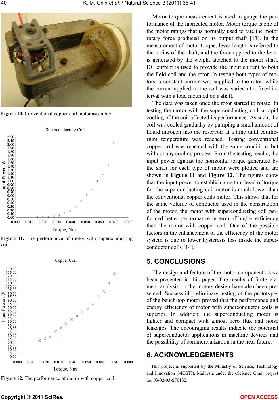 K. M. Chin et al. / Natural Science 3 (2011) 36-41 Copyright © 2011 SciRes. OPEN ACCESS 40 Figure 10. Conventional copper coil motor assembly. Figure 11. The performance of motor with superconducting coil. Figure 12. The performance of motor with copper coil. Motor torque measurement is used to gauge the per- formance of the fabricated motor. Motor torque is one of the motor ratings that is normally used to rate the motor rotary force produced on its output shaft [13]. In the measurement of motor torque, lever length is referred to the radius of the shaft, and the force applied to the lever is generated by the weight attached to the motor shaft. DC current is used to provide the input current to both the field coil and the rotor. In testing both types of mo- tors, a constant current was supplied to the rotor, while the current applied to the coil was varied at a fixed in- terval with a load mounted on a shaft. The data was taken once the rotor started to rotate. In testing the motor with the superconducting coil, a rapid cooling of the coil affected its performance. As such, the coil was cooled gradually by pumping a small amount of liquid nitrogen into the reservoir at a time until equilib- rium temperature was reached. Testing conventional copper coil was repeated with the same conditions but without any cooling process. From the testing results, the input power against the horizontal torque generated by the shaft for each type of motor were plotted and are shown in Figure 11 and Figure 12. The figures show that the input power to establish a certain level of torque for the superconducting coil motor is much lower than the conventional copper coils motor. This shows that for the same volume of conductor used in the construction of the motor, the motor with superconducting coil per- formed better performance in term of higher efficiency than the motor with copper coil. One of the possible factors in the enhancement of the efficiency of the motor system is due to lower hysteresis loss inside the super- conductor coils [14]. 5. CONCLUSIONS The design and feature of the motor components have been presented in this paper. The results of finite ele- ment analysis on the motors design have also been pre- sented. Successful preliminary testing of the prototypes of the bench-top motor proved that the performance and energy efficiency of motor with superconductor coils is superior. In addition, the superconducting motor is lighter and compact with almost zero flux and noise leakages. The encouraging results indicate the potential of superconductor applications in machine devices and the possibility of commercialization in the near future. 6. ACKNOWLEDGEMENTS This project is supported by the Ministry of Science, Technology and Innovation (MOSTI), Malaysia under the eScience Grant project no. 03-02-03-SF0132. 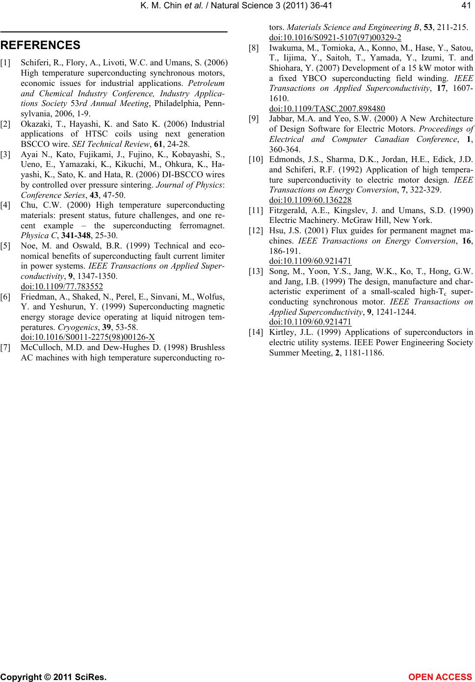 K. M. Chin et al. / Natural Science 3 (2011) 36-41 Copyright © 2011 SciRes. OPEN ACCESS 4141 REFERENCES [1] Schiferi, R., Flory, A., Livoti, W.C. and Umans, S. (2006) High temperature superconducting synchronous motors, economic issues for industrial applications. Petroleum and Chemical Industry Conference, Industry Applica- tions Society 53rd Annual Meeting, Philadelphia, Penn- sylvania, 2006, 1-9. [2] Okazaki, T., Hayashi, K. and Sato K. (2006) Industrial applications of HTSC coils using next generation BSCCO wire. SEI Technical Review, 61, 24-28. [3] Ayai N., Kato, Fujikami, J., Fujino, K., Kobayashi, S., Ueno, E., Yamazaki, K., Kikuchi, M., Ohkura, K., Ha- yashi, K., Sato, K. and Hata, R. (2006) DI-BSCCO wires by controlled over pressure sintering. Journal of Physics: Conference Series, 43, 47-50. [4] Chu, C.W. (2000) High temperature superconducting materials: present status, future challenges, and one re- cent example – the superconducting ferromagnet. Physica C, 341-348, 25-30. [5] Noe, M. and Oswald, B.R. (1999) Technical and eco- nomical benefits of superconducting fault current limiter in power systems. IEEE Transactions on Applied Super- conductivity, 9, 1347-1350. doi:10.1109/77.783552 [6] Friedman, A., Shaked, N., Perel, E., Sinvani, M., Wolfus, Y. and Yeshurun, Y. (1999) Superconducting magnetic energy storage device operating at liquid nitrogen tem- peratures. Cryogenics, 39, 53-58. doi:10.1016/S0011-2275(98)00126-X [7] McCulloch, M.D. and Dew-Hughes D. (1998) Brushless AC machines with high temperature superconducting ro- tors. Materials Science and Engineering B, 53, 211-215. doi:10.1016/S0921-5107(97)00329-2 [8] Iwakuma, M., Tomioka, A., Konno, M., Hase, Y., Satou, T., Iijima, Y., Saitoh, T., Yamada, Y., Izumi, T. and Shiohara, Y. (2007) Development of a 15 kW motor with a fixed YBCO superconducting field winding. IEEE Transactions on Applied Superconductivity, 17, 1607- 1610. doi:10.1109/TASC.2007.898480 [9] Jabbar, M.A. and Yeo, S.W. (2000) A New Architecture of Design Software for Electric Motors. Proceedings of Electrical and Computer Canadian Conference, 1, 360-364. [10] Edmonds, J.S., Sharma, D.K., Jordan, H.E., Edick, J.D. and Schiferi, R.F. (1992) Application of high tempera- ture superconductivity to electric motor design. IEEE Transactions on Energy Conversion, 7, 322-329. doi:10.1109/60.136228 [11] Fitzgerald, A.E., Kingslev, J. and Umans, S.D. (1990) Electric Machinery. McGraw Hill, New York. [12] Hsu, J.S. (2001) Flux guides for permanent magnet ma- chines. IEEE Transactions on Energy Conversion, 16, 186-191. doi:10.1109/60.921471 [13] Song, M., Yoon, Y.S., Jang, W.K., Ko, T., Hong, G.W. and Jang, I.B. (1999) The design, manufacture and char- acteristic experiment of a small-scaled high-Tc super- conducting synchronous motor. IEEE Transactions on Applied Superconductivity, 9, 1241-1244. doi:10.1109/60.921471 [14] Kirtley, J.L. (1999) Applications of superconductors in electric utility systems. IEEE Power Engineering Society Summer Meeting, 2, 1181-1186. |