

Paper Menu >>
Journal Menu >>
 Journal of Sustainable Bioenergy Systems, 2013, 3, 234-241 http://dx.doi.org/10.4236/jsbs.2013.33032 Published Online September 2013 (http://www.scirp.org/journal/jsbs) Co-Gasification of Mesquite and Coal Blend in an Updraft Fixed Bed Gasifier Wei Chen1, Siva Sankar Thanapal1, Kal ya n Anna malai1, Robert James Ansley2, Mustafa Mirik2 1Department of Mechanical Engineering, Texas A&M University, College Station, USA 2Texas AgriLife Research, Vernon, USA Email: [email protected] Received July 10, 2013; revised August 11, 2013; accepted August 30, 2013 Copyright © 2013 Wei Chen et al. This is an open access article distributed under the Creative Commons Attribution License, which permits unrestricted use, distribution, and reproduction in any medium, provided the original work is properly cited. ABSTRACT In order to reduce the emission of NOx, SOx, and CO2 and mitigate the dependen ce on the fossil fuel, the use of renew- able energy, especially the biomass energy, has been explored. Since most biomass fuels are hard to grind to the very fine size, gasification is the preferred technology of energy conversion. Updraft fixed bed gasification using partial oxi- dation process is adopted where air less than the stoichiometric quantity is admitted to oxidize the char to CO. The temperature profile within th e b ed reveals a characteristic temperature peak. The results reveal a correlation between the higher heating value (HHV) of producer gas and the peak gasification temperature (Tpeak). Coal with higher char content (~45%) is blended with biomass of low char content (~20%) in order to produce high quality gas. In this study, the Texas-based mesquite fuel was blended with Wyoming Power River Basin (PRB) coal with mass ratios of 100:0, 90:10, and 80:20 and fired downward into the gasifier. It was found that at a given mesquite to the coal mass ratio, the peak gasification temperature decreased with the increase in ER. With the increase of the coal ratio in the mesquite: coal blend and the peak temperature increased significantly; more combustible gases such as CO, CH4 were generated at the end of product gas, and the HHV of the product gas increased by 10% - 20%. Keywords: Gasification; Bioenergy; Coal; Heating Value; Sustainability 1. Introduction The utilization of wastes as a renewab le energy source in a thermo-chemical process to generate electricity or heat has been widely used. The US independent biomass en- ergy industry today provides for the disposal of ap- proximately 22 million tons/yr of solid biomass waste [1]. Brian et al. [2] reported that approximately 60% of bio- mass energy consumption occurs in the forest products industry in US. The forest produ cts industry produces its own sources of biomass such as bark, sawdust, wood scraps/shavings, and waste water treatment sludge. Nor- mally, bio-chemical and thermo-chemical are the two main ways to convert biomass into energy. Gasification is a thermo-chemical process where a solid fuel was converted into gaseous species through a series of chemical reactions and physical transformation. Air, steam, and pure oxygen are the three main gasifying me- dia, although other agents like CO2 or H2 are also being studied. The gasifiers can generally be classified into two dif- ferent types: fixed bed and fluidized bed gasifier. For fixed bed gasifier, the flow velocity is low; there is a grate at the bottom of the gasifier and ash was disposed through the grate while the flow velocity is high and there is no grate for the fluidized bed gasifier. The fixed bed gasifier can be classified as updraft, downdraft, and crossdraft. The updraft fixed bed gasifier is a counterflow reactor in which fuel is fed into the top and the air or the steam is supplied at the bottom. The ash was removed through the grate. In a downdraft fixed bed gasifier, fuel and gases both flow in the same direction. Fixed bed gasifiers are well suited for small-scale applications (Power < 10 MW) [3]. Fluidized bed gasifier usually has a large scale size and is used for industrial applications. For mesquite and coal co-gasification, the updraft fixed bed gasifier is used since it is easy to construct and oper- ate. The temperature of gas coming out from the updraft gasifier is less than 200˚C [4]. 2. Literature Review and Objective Extensive studies have been carried out on the biomass gasification using air, steam, or air-steam mixture as C opyright © 2013 SciRes. JSBS  W. CHEN ET AL. 235 gasification media. Kumabe et al. [5] carried out the co- gasification experiments using Japanese cedar and Mu- lias coal in a downdraft gasifier by using air and steam as gasification media. It was found that with an increase in the biomass ratio in the mixture, the H2 % decreased and the CO2% increased while the CO % was independent of the biomass ratio. A low biomass ratio led to the produc- tion of a gas favorable for methanol and hydrocarbon fuel synthesis, and a high biomass ratio led to the pro- duction of a gas favorable for Dimethyl Ether (DME) synthesis. The cold gas efficiency of the co-gasification ranged from 65% to 85%. Pan et al. [6] mixed the pine chips with black coal and Sabero coal, in the ratio range of 0/100 - 100/0, respec- tively. Experimental tests were carried out using air and steam as gasification agent at gasification temperatures of 840˚C - 910˚C and superficial fluidized gas velocities of 0.7 - 1 .4 m/s using fludized bed gasifier. It was found that the dry product gas heating value increases with in- creasing blend ratio from 3700 to 4560 kJ/Nm3 for pine chips/black coal, and from 40 00 to 4750 kJ/Nm3 for pine chips/Sabero. Dry product gas yield raised with the in- crease of the blend ratio from 1.80 to 3.20 Nm3/kg (pine chips/black coal), and from 0.75 to1.75 Nm3/kg (pine chips/Sabero coal), respectively. About 50% co-gasifi- cation processes overall thermal efficiency can be achieved for the two types of blend. Lu et al. [7] studied the effect of the equivalence ratio on the co-gasification of pine sawdust and bituminous coal in a bubbling fluidized bed. It was found that when blending fuel ratio is 50% - 50%, with ER increasing from 0.2 to 0.28 the volume concentration of H2 rose from 14.1% to 26.9%, and CO% decreased from 28.9% to 21.8%. The CO2% showed an increasing tendency in the range of ER, while those of CH4 and CnHm kept de- creasing. The maximum of the lower heating value (LHV), is about 7180 kJ/m3 when ER is 0.25. The gasi- fication efficiency ranged from 44% - 53% and the car- bon con- version rate was between74% to 76%. Chen et al. [8] used the mesquite wood chips as feed- stock for a fixed bed gasification experiment. It was found that the HHV of the gas produced from the mes- quite fuel decreased when equivalence ratio (ER) in- creased from 2.7 to 4.2 and the HHV was in a range of 2400 kJ/Nm3 to 3500 kJ/Nm3. Gerado et al. [9] used a mixture of dairy biomass (DB) and Wyoming sub-bituminous coal (WYC) with a ratio of 90:10 for co-gasification study in a 10 kW updraft gasifier using air-steam as gasification media. Due to the presence of higher amount of fixed carbon in the WYC, the peak gasification temperature and the % of CO in the end produced gas increased and the HHV of the producer gas increased correspondingly. The HHV of the gases varied from 3649 to 4793 kJ/ Nm3. In these studies, the variation of HHV of the gases produced and the gasification efficiency with ER and mesquite: coal r atios were investig ated. It was also found that the HHV of the product gas increased as coal % was increased in the blends. In the current study, the Texas based mesquite was blended with PRB coal for air gasifi- cation in order to produce higher quality gas (i.e. in- creased HV gas) and convert more volatile matter into combustible gases (e.g. reduce the tar content in the product gas due to higher Tpeak). The effect of the ER and coal% in mesquite: coal blend (MCB) on the gasification temperature, gas compositions, and HHV were investi- gated. The main objective of this study was to use the Texas based Mesquite and PRB coal blended fuel to pro- duce higher quality gas (i.e. increased HV gas) and con- vert more volatile matter into combustible gases (e.g. reduce the tar content in the product gas due to higher Tpeak) in an air gasification process. The effect of the ER and coal percentage in mesquite: coal blend (MCB) on the gasification temperature, gas compositions, and HHV were investigated. 3. Sustainabilityof Mesquite The sustainability of any energy source must satisfy the following requirements: Abundance of energy sources, maintaining integrity of environment including air, land (soil) and water, renewability and affordability (i.e. low cost)[10]. Most biomass fuels satisfy the requirement including mesquite. The Mesquite (Prosopis glandulosa) is a deciduous wood which can reach a height of 6 to 9 m (20 to 30 ft), grows rapidly and furnish shade and wild- life habitat where other trees will not grow [11]. It is an extremely hardy, drought-tolerant plant growing on semi- arid non-cultivated land s because it can draw water from the water table through its long taproot and thus it can be harvested nearly year round [11,12]. Depending upon availability, mesquite can also use water in the upper part of the ground. Mesquite trees have very strong regrowth after top-kill damage [12]. Like many members of the Legume Family, it fixes nitrogen in the soil where it grows and therefore satisfies most of its nutrient needs [13]. It is estimated that of the 21 M total h a of mesquite in Texas alone [14,15] , about 20%, or 4.2 M ha, could be harvested for bioenergy needs. At an average of 18 dry Mg/ha [12], this could amount to over 75 teragrams (Tg) of total mass available. There is no planting, culti- vation, irrigation and fertilization costs for this naturally occurring, nitrogen-fixing species [12]. This species can be used as feedstock to produce syngas and bio-oil in small scale gasification units [4]. Since coal has higher amount of char compared to mesquite, then the heat value of gas produced could be enhanced by blending small amount of coal with mesquite; such a process in- creases the usage of gas produced from gasification of Copyright © 2013 SciRes. JSBS 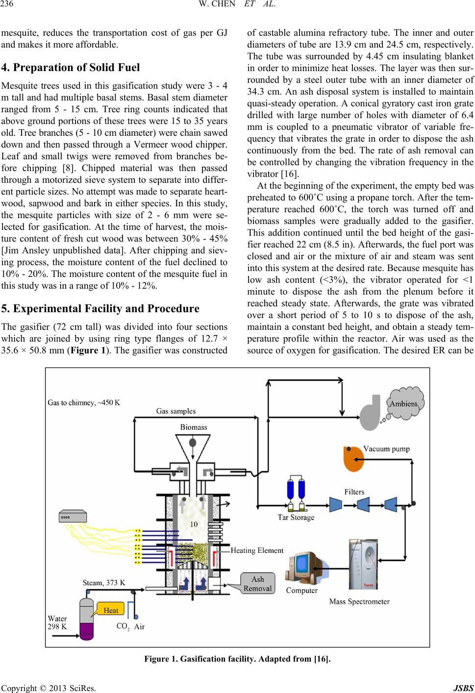 W. CHEN ET AL. Copyright © 2013 SciRes. JSBS 236 mesquite, reduces the transportation cost of gas per GJ and makes it more affordable. 4. Preparation of Solid Fuel Mesquite trees used in this gasification study were 3 - 4 m tall and had multiple basal stems. Basal stem diameter ranged from 5 - 15 cm. Tree ring counts indicated that above ground portions of these trees were 15 to 35 years old. Tree branches (5 - 10 cm diameter) were chain sawed down and then passed through a Vermeer wood chipper. Leaf and small twigs were removed from branches be- fore chipping [8]. Chipped material was then passed through a motorized sieve system to separate into differ- ent particle sizes. No attempt was made to separate heart- wood, sapwood and bark in either species. In this study, the mesquite particles with size of 2 - 6 mm were se- lected for gasification. At the time of harvest, the mois- ture content of fresh cut wood was between 30% - 45% [Jim Ansley unpublished data]. After chipping and siev- ing process, the moisture content of the fuel declined to 10% - 20%. The moisture content of the mesquite fuel in this study was in a range of 10% - 12%. 5. Experimental Facility and Procedure The gasifier (72 cm tall) was divided into four sections which are joined by using ring type flanges of 12.7 × 35. 6 × 50 .8 mm (Figure 1). The gasifier was constructed of castable alumina refractory tube. The inner and outer diameters of tube are 13.9 cm and 24.5 cm, respectively. The tube was surrounded by 4.45 cm insulating blanket in order to minimize heat losses. The layer was then sur- rounded by a steel outer tube with an inner diameter of 34.3 cm. An ash disposal system is installed to maintain quasi-steady operation. A conical gyratory cast iron grate drilled with large number of holes with diameter of 6.4 mm is coupled to a pneumatic vibrator of variable fre- quency that vibrates the grate in order to dispose the ash continuously from the bed. The rate of ash removal can be controlled by changing the vibration frequency in the vibrator [16]. At the beginning of the experiment, the empty bed was preheated to 600˚C using a propane torch. After the tem- perature reached 600˚C, the torch was turned off and biomass samples were gradually added to the gasifier. This addition continued until the bed height of the gasi- fier reached 22 cm (8.5 in). Afterwards, the fuel port was closed and air or the mixture of air and steam was sent into this system at the desired rate. Because mesquite has low ash content (<3%), the vibrator operated for <1 minute to dispose the ash from the plenum before it reached steady state. Afterwards, the grate was vibrated over a short period of 5 to 10 s to dispose of the ash, maintain a constant bed height, and obtain a steady tem- perature profile within the reactor. Air was used as the source of oxygen for gasification. The desired ER can be Figure 1. Gasification facility. Adapted from [16]. 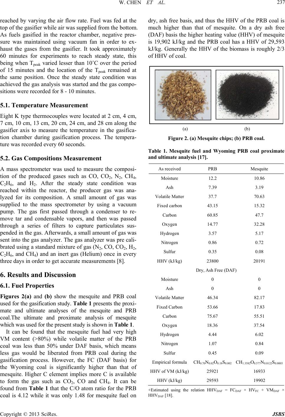 W. CHEN ET AL. 237 reached by varying the air flow rate. Fuel was fed at the ted at 2 cm, 4 cm, ent the composi- ow the mesquite and PRB coal dry, ash free basis, and thus the HHV of the PRB coal is top of the gasifier while air was supplied from the bottom. As fuels gasified in the reactor chamber, negative pres- sure was maintained using vacuum fan in order to ex- haust the gases from the gasifier. It took approximately 60 minutes for experiments to reach steady state, this being when Tpeak varied lesser than 10˚C over the period of 15 minutes and the location of the Tpeak remained at the same position. Once the steady state condition was achieved the gas analysis was started and the gas compo- sitions were recorded for 8 - 10 minutes. 5.1. Temperature Measurement Eight K type thermocouples were loca 7 cm, 10 cm, 13 cm, 20 cm, 24 cm, and 28 cm along the gasifier axis to measure the temperature in the gasifica- tion chamber during gasification process. The tempera- ture was recorded every 60 seconds. 5.2. Gas Compositions Measurem A mass spectrometer was used to measure tion of the produced gases such as CO, CO2, N2, CH4, C2H6, and H2. After the steady state condition was reached within the reactor, the producer gas was ana- lyzed for its composition. A small amount of gas was supplied to the mass spectrometer by using a vacuum pump. The gas first passed through a condenser to re- move tar and condensable vapors, and then was passed through a series of filters to capture particulates sus- pended in the gas. Afterwards, a small amount of gas was sent into the gas analyzer. The gas analyzer was pre cali- brated using a standard mixture of gas (N2, CO, CO2, H2, C2H6, and CH4) and an inert gas (Helium) once in every three days in order to get accurate measurements [8]. 6. Results and Discussion 6.1. Fuel Properties Figures 2(a) and (b) sh used for the gasification study. Table 1 presents the proxi- mate and ultimate analyses of the mesquite and PRB coal.The ultimate and proximate analysis of mesquite which was used for the present study is shown i n Table 1. It can be found that the mesquite fuel had very high VM content (>80%) while volatile matter of the PRB coal was less than 50% under DAF basis, which means less gas would be liberated from PRB coal during the gasification process. However, the FC (DAF basis) for the Wyoming coal is significantly higher than that of mesquite. Higher C element implies more C is available to form the gas such as CO2, CO and CH4. It can be found from Table 1 that the C/O atom ratio for the PRB coal is 4.12 while it was only 1.48 for mesquite fuel on much higher than that of mesquite. On a dry ash free (DAF) basis the higher heating value (HHV) of mesquite is 19,902 kJ/kg and the PRB coal has a HHV of 29,593 kJ/kg. Generally the HHV of the biomass is roughly 2/3 of HHV of coal. (a) (b) Figure 2. (a) Mesquite chips; (b) PRB coal. Table 1. Mesqal proximate and ultimate an As received PRB Mesquite uite fuel and Wyoming PRB co alysis [17]. Moisture 12.2 10.86 Ash 7.39 3.19 Volatile M Fixed car43. Nitr HHV (kJ/kg) 23802019 Dry, Ash Fee (DAF) Moisture 0 Ash 0 0 Volatile Matter 82.17 Fixed Carbon 53.17. Car 55. Hy Nitr Empirula CH0.70N8S0.002 CH1.3582O0.5 .0122S0.0003 HHV of VM (kJ/kg)25921693 1990 atter bon 37.7 15 70.63 15.32 Carbon 60. Oxygen 14. 85 77 47.7 32.28 Hydrogen 3.57 5.17 ogen 0. Sulfur 0. 86 35 0.72 0.08 0 r 1 0 46.34 66 67 83 51 bon 75. Oxygen 18.36 37.54 drogen 4. ogen 1. 44 07 6.02 0.84 Sulfur 0. ical form 45 O 0.09 N 0.02 0.1 1 77 0 3 HHV (kJ/kg) 29593 2 +lation HHVF = FCDAF × HVMDAF × HEstimated using the re HVDAF [18]. DA FC + V Copyright © 2013 SciRes. JSBS 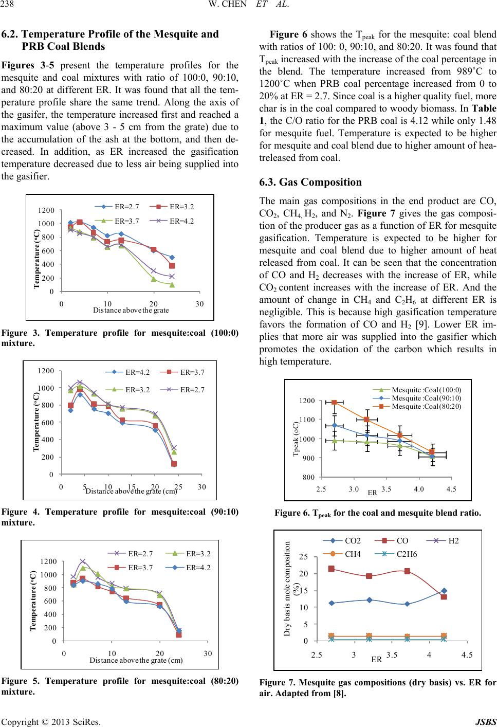 W. CHEN ET AL. 238 6.2ture Prf the Mesqud 5 present the temperature profiles for the 0, - peratsame trend. Along the axis of . Temperaofile oite an PRB Coal Blends Figures 3- mesquite and coal mixtures with ratio of 100:0, 90:1 and 80:20 at different ER. It was found that all the tem ure profile share the the gasifer, the temperature increased first and reached a maximum value (above 3 - 5 cm from the grate) due to the accumulation of the ash at the bottom, and then de- creased. In addition, as ER increased the gasification temperature decreased due to less air being supplied into the gasifier. 0 200 400 600 800 1000 1200 C) 0102030 Temp erature ( o Distance above t he g rate ER=2.7 ER=3.2 ER=3.7 ER=4.2 Figure 3. Temperature profile for mesquite:coal (100:0) mixture. 0 200 400 600 800 1000 C) 1200 0510 15 20 25 30 T emperature ( o Distance above the g rate (cm) ER=4.2ER=3.7 ER=3.2ER=2.7 Figure 4. Temperature profile for mesquite:coal (90:10) mixture. 0 200 400 600 800 1000 1200 o C) 0102030 T emperature ( Distance abo ve the g rate (cm ) ER=2.7 ER=3.2 ER=3.7 ER=4.2 Figure 5. Temperature profile for mesquite:coal (80:20) mixture. Figure 6 shows the Tpeak for the mesquite: coal blend with ratios of 100: 0, 90:10, and 80:20. It was found that Tpeak increased with the increase of the coal percentage in the blend. The temperature increased from 989˚C to 1200˚C when PRB coal percentage increased from 0 to 20% at ER = 2.7. Since coal is a higher quality fuel, more char is in the coal compared to woody biomass. In Table 1, the C/O ratio for the PRB coal is 4.12 while only 1.48 for mesquite fuel. Temperature is expected to be higher for mesquite and coal blend due to higher amount of- treleased from coal. Composition ause high gasification temperature favors the formation of CO and H2 [9]. Lower ER im- pplied into the gasifier which hea 6.3. Gas The main gas compositions in the end product are CO, CO2, CH4, H2, and N2. Figure 7 gives the gas composi- tion of the producer gas as a function of ER for mesquite gasification. Temperature is expected to be higher for mesquite and coal blend due to higher amount of heat released from coal. It can be seen that the concentration of CO and H2 decreases with the increase of ER, while CO2 content increases with the increase of ER. And the amount of change in CH4 and C2H6 at different ER is negligible. This is bec plies that more air was su promotes the oxidation of the carbon which results in high temperature. 800 900 1000 1100 1200 2.5 3.0 3.5 4.0 4.5 Tpeak (oC ) ER Mesquite :Coal (100:0) Mesquite :Coal (90:10) Mesquite :Coal (80:20) Figure 6. Tpeak for the coal and mesquite blend ratio. 0 5 10 15 20 25 2.5 33.5 44.5 D ry b asi s m o le c o m p os i ti on (%) ER CO2 CO H2 CH4 C2H6 Figure 7. Mesquite gas compositions (dry basis) vs. ER for air. Adapted from [8]. Copyright © 2013 SciRes. JSBS 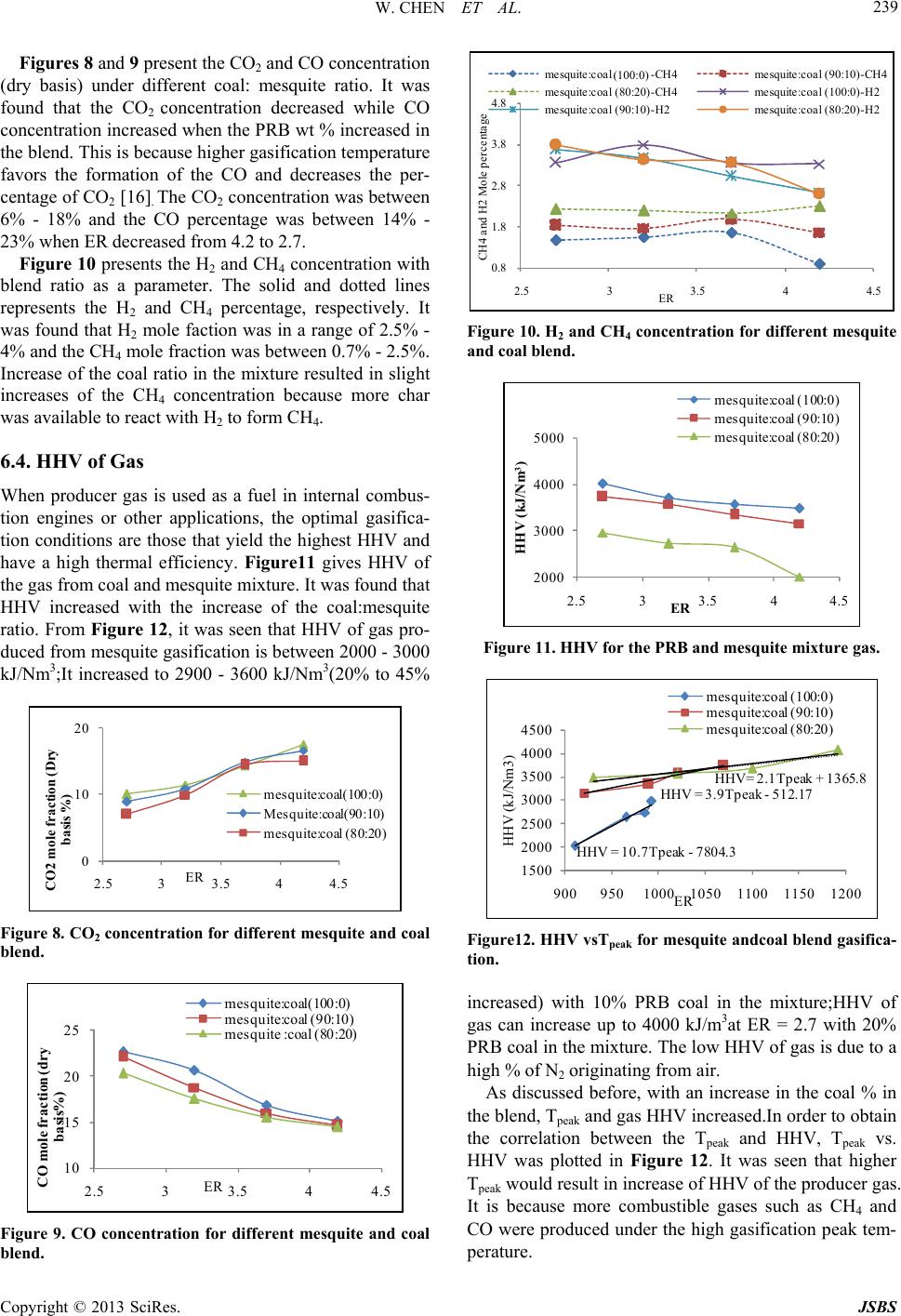 W. CHEN ET AL. 239 Figures 8 and 9 present the CO2 and CO concentration (dry basis) under different coal: mesquite ratio. It was found that the CO2 concentration decreased while CO concentration increased when the PRB wt % increased in the blend. This is because higher gasification temperature favors the formation of the CO and decreases the per- centage of CO2 [16]. The CO2 concentration was between 6% - 18% and the CO percentage was between 14% - 23% when ER decreased from 4.2 to 2.7. Figure 10 presents the H2 and CH4 concentration with blend ratio as a parameter. The solid and dotted lines represents the H and CH percentage, respectively 2 4 was found that H2 mole faction was in a range of 2.5% - 4% and the CH mole fract . It 4ion was between 0.7% - 2.5%. Increase of the coal ratio in the mixture resulted in slight increases of the CH4 concentration because more char was available to react with H2 to form CH4. 6.4. HHV of Gas When producer gas is used as a fuel in internal combus- tion engines or other applications, the optimal gasifica- tion conditions are those that yield the highest HHV and have a high thermal efficiency. Figure11 gives HHV of the gas from coal and mesquite mixture. It was found that HHV increased with the increase of the coal:mesquite ratio. From Figure 12, it was seen that HHV of gas pro- duced from mesquite gasification is between 2000 - 3000 kJ/Nm3;It increased to 2900 - 3600 kJ/Nm3(20% to 45% 0 10 2.533.544.5 C O2 m ol e f rac ti o basis %) ER 20 n (D ry me squite:c oal(100:0) Me squite:coal(90 : 10) mesquite: coa l (80:2 0) Figure 8. CO2 concentration for different mesquite and coal blend. 10 15 20 25 2.5 33.5 44.5 CO m ole fr acti o n (d ry basis%) ER mesquite:coal(100:0) mesquite:coa l (90 :1 0) mesquite :co al (80:20 ) Figure 9. CO concentration for different mesquite and coal blend. 0.8 1.8 2.8 3.8 4.8 2.533.544 CH4 and H2 Mole percenta ge ER .5 me squite:coal (0:100)-CH4me squite:coal (90:10)-CH4 me squite:coal (80:20)-CH4me squite:coal (100:0)-H2 me squite:coal (90:10)-H2me squite:coal (80:20)-H2 (100:0) Figure 10. H2 and CH4 concentration for different mesquite and coal blend. 2000 3000 4000 5000 2.5 33.5 44.5 HHV (kJ/Nm 3 ) ER mesquit e : c oa l (10 0: 0) mesquite: coal (90:10) mesquite: coal (80:20) Figure 11. HHV for the PRB and mesquite mixture gas. H HV = 10. 7Tpe ak -7804 . 3 H HV = 3. 9Tpea k -5 12 . 1 7 HHV= 2.1Tpea k + 136 5 .8 1500 2000 2500 3000 3500 4000 4500 9009501000 1050 1100 1150 1200 HHV (kJ/Nm3) ER mesquite: coal (100 :0) mesquite: coal (90:1 0) mesquite: coal (80:2 0) Figure12. HHV vsTpeak for mesquite andcoal blend gasifica- ti d) with 10% PRB coal in the mixture;HHV of gas can increase up to 4000 kJ/m3at ER = 2.7 with 20% PRB coal in the mixture. The low HHV of gas is due to a high % of N2 originating from air. As discussed before, with an increase in the coal % in the blend, Tpeak and gas HHV increased.In order to obtain the correlation between the Tpeak and HHV, Tpeak vs. HHV was plotted in Figure 12. It was seen that higher Tpeak would result in increase of HHV of the producer gas. It is because more combustible gases such as CH4 and CO were produced under th e high gasification peak tem- perature. on. increase Copyright © 2013 SciRes. JSBS 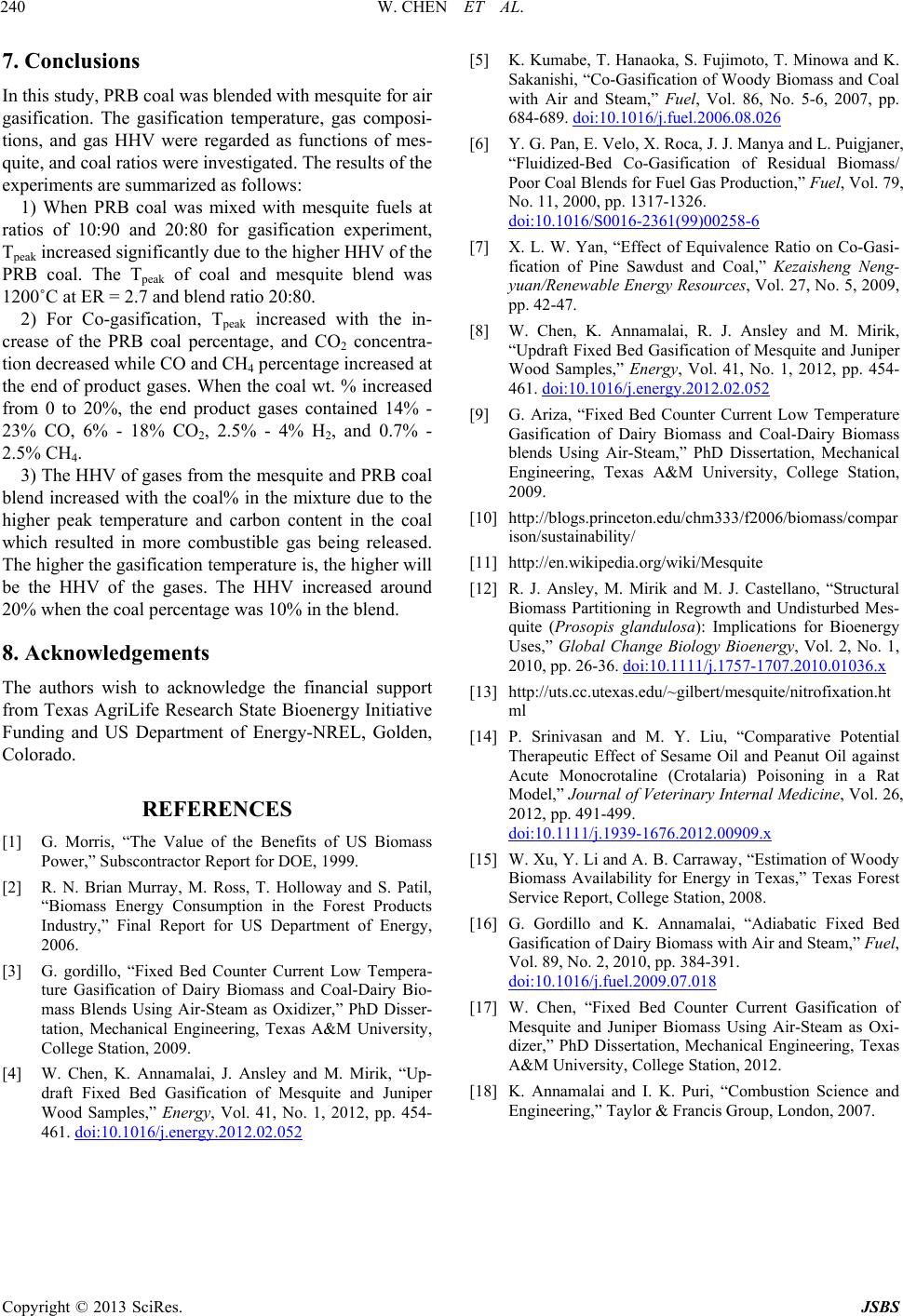 W. CHEN ET AL. Copyright © 2013 SciRes. JSBS 240 this study, PRB coal was blended with mesquite for air ows: 4 product gases. When the coal wt. % increa end product gases contained 1 % CO, 2.5% - 4% H, and 0.7% - ing released Th REFERENCES - omass and Coal-Dairy eam as Oxidizer,” PhD Disser- mples,” Energy, Vol. 41, No. 1, 2012, pp. 454- 461. doi:10.1016/j.energy.2012.02.052 7. Conclusions In gasification. The gasification temperature, gas composi- tions, and gas HHV were regarded as functions of mes- quite, and co al ratios were investigated. The results of the experiments are summarized as foll 1) When PRB coal was mixed with mesquite fuels at ratios of 10:90 and 20:80 for gasification experiment, Tpeak increased significantly due to the higher HHV of the PRB coal. The Tpeak of coal and mesquite blend was 1200˚C at ER = 2.7 and blend rati o 2 0:80. 2) For Co-gasification, Tpeak increased with the in- crease of the PRB coal percentage, and CO2 concentra- tion decreased while CO and CH percentage increased at the end of sed 4% - from 0 to 20%, the 23% CO, 6% - 182 2 2.5% CH4. 3) The HHV of gases from the mesquite and PRB coal blend increased with the coal% in the mixture due to the higher peak temperature and carbon content in the coal which resulted in more combustible gas be. e higher the gasification temperature is, the higher will be the HHV of the gases. The HHV increased around 20% when the coal percentage was 10% in the blend. 8. Acknowledgements The authors wish to acknowledge the financial support from Texas AgriLife Research State Bioenergy Initiative Funding and US Department of Energy-NREL, Golden, Colorado. [1] G. Morris, “The Value of the Benefits of US Biomass Power,” Subscontractor Report for DOE, 1999. [2] R. N. Brian Murray, M. Ross, T. Holloway and S. Patil, “Biomass Energy Consumption in the Forest Products Industry,” Final Report for US Department of Energy, 2006. [3] G. gordillo, “Fixed Bed Counter Current Low Tempera ture Gasification of Dairy Bi mass Blends Using Air-St Bio- tation, Mechanical Engineering, Texas A&M University, College Station, 2009. [4] W. Chen, K. Annamalai, J. Ansley and M. Mirik, “Up- draft Fixed Bed Gasification of Mesquite and Juniper Wood Sa and Steam,” Fuel, Vol. 86, No. 5-6, 2007, pp. [5] K. Kumabe, T. Hanaoka, S. Fujimoto, T. Minowa and K. Sakanishi, “Co-Gasification of Woody Biomass and Coal with Air 684-689. doi:10.1016/j.fuel.2006.08.026 [6] Y. G. Pan, E. Velo, X. Roca, J. J. Many a and L. Puigjaner, “Fluidized-Bed Co-Gasification of Residual Biomass/ Poor Coal Blends for Fuel Gas Production,” Fuel, Vol. 79, No. 11, 2000, pp. 1317-1326. doi:10.1016/S0016-2361(99)00258-6 [7] X. L. W. Yan, “Effect of Equivalence Ratio on Co-Gasi- fication of Pine Sawdust and Coal,” Kezaisheng Neng- yuan/Renewable Energy Resources, Vol. 27, No. 5, 2009, , 2012, pp. 454- pp. 42-47. [8] W. Chen, K. Annamalai, R. J. Ansley and M. Mirik, “Updraft Fixed Bed Gasification of Mesquite and Juniper Wood Samples,” Energy, Vol. 41, No. 1 461. doi:10.1016/j.energy.2012.02.052 [9] G. Ariza, “Fixed Bed Counter Current Low Temperature Gasification of Dairy Biomass and Coal-Dairy Biomass blends Using Air-Steam,” PhD Engineering, Texas A&M University Dissertation, Mechanical , College Station, ipedia.org/wiki/Mesquite gy, Vol. 2, No. 1, 2009. [10] http://blogs.princeton.edu/chm333/f2006/biomass/compar ison/sustainability/ [11] http://en.wik [12] R. J. Ansley, M. Mirik and M. J. Castellano, “Structural Biomass Partitioning in Regrowth and Undisturbed Mes- quite (Prosopis glandulosa): Implications for Bioenergy Uses,” Global Change Biology Bioener 2010, pp. 26-36. doi:10.1111/j.1757-1707.2010.01036.x [13] http://uts.cc.utexas.edu/~gilbert/mesquite/nitrofixation.ht ml [14] P. Srinivasan and M. Y. Liu, “Comparative Potential Therapeutic Effect of Sesame Oil and Peanut Oil against Acute Monocrotaline (Crotalaria) Poisoning in a Rat Model,” Journal of Veterinary Internal Medicine, Vol. 26, 2012, pp. 491-499. doi:10.1111/j.1939-1676.2012.00909.x [15] W. Xu, Y. Li and A. B. Carraway, “Estimation of Woody Biomass Availability for Energy in Texas,” Texas Forest Service Report, College Station, 2008. [16] G. Gordillo and K. Annamalai, “Adiabatic Fixed Bed , . 89, No. 2, 2010, pp. 384-391. Gasification of Dairy Biomass with Air and Steam,” Fuel Vol doi:10.1016/j.fuel.2009.07.018 [17] W. Chen, “Fixed Bed Counter Current Gasification of Mesquite and Juniper Biomass Using Air-Steam as Oxi- dizer,” PhD Dissertation, Mechanical Engineering, Texas A&M University, Co [18] K. Annamalai and I. K. Puri, “Combus llege Station, 2012. tion Science and Engineering,” Taylor & Francis Group, London, 2007.  W. CHEN ET AL. 241 Nomenclature CO: Carbon Monoxide HHV: Higher Heating Val ue CO C2: Carbon Dioxide H4: Methane 2H6: Ethane AF: Dry, Ash Free Basis ME: Dimethyl Ether R: Equivalence Ratio C: Fixed Carbon in Temperature r C D D E F LHV: Lower Heating Value MCB: Mesquite to Coal Blend N2: Nitrogen O2: Oxygen PRB: Powder River Bas Tpeak: Peak Gasification VM: Volatile Matte Copyright © 2013 SciRes. JSBS |