

Paper Menu >>
Journal Menu >>
 Journal of Electronics Cooling and Thermal Control, 2013, 3, 85-93 http://dx.doi.org/10.4236/jectc.2013.33010 Published Online September 2013 (http://www.scirp.org/journal/jectc) Investigation of Thermal Characterization of a Thermally Enhanced FC-PBGA Assembly C. F. Lin1, G. H. Wu1*, S. H. Ju2 1Department of Mechanical Engineering, National Cheng-Kung University, Tainan, Taiwan 2Department of Civil Engineering, National Cheng-Kung University, Tainan, Taiwan Email: *[email protected], [email protected] Received January 1, 2013; revised February 1, 2013; accepted February 10, 2013 Copyright © 2013 C. F. Lin et al. This is an open access article distributed under the Creative Commons Attribution License, which permits unrestricted use, distribution, and reproduction in any medium, provided the original work is properly cited. ABSTRACT In this paper, three-dimensional finite element analysis using the commercial ANSYS software is performed to study the thermal performance of a thermally enhanced FC-PBGA (flip-chip plastic ball grid array) assembly in both natural and forced convection environments. The thermally enhanced FC-PBGA assembly is a basic FC-PBGA assembly with a lid attached on top, after which an ex truded-fin heatsink is attached on the top of the lid. The finite element model is complete enough to include key elements such as bumps, solder balls, substrate, printed circuit board, extruded-fin heatsink, lid, vias, TIM1 (thermal interface material 1), TIM2 (thermal interface material 2), lid-substrate adhesive and ground planes for both signal an d pow er. Temperature fields are simulated and presented for several package configura- tions. Thermal resistance is calculated to characterize and compare the thermal performance by considering alternative design parameters of the polymer-based materials and the thermal enhancement components. The polymer-based mate- rials include underfill, TIM1, TIM2, lid-substrate adhesive and substrate core material. The specific thermal enhance- ment components are the extruded-fin heatsink and the lid. Keywords: Polymer-Based Materials; Flip-Chip Packaging; Finite Element Methods 1. Introduction Due to increasing demand for high density, high I/O, high performance electrical application and flip-chip pla- stic ball grid array (FC-PBGA) packaging are rapidly be- coming the package of choice. FC-PBGA technology offers many advantages over the popular PBGA. Com- monly stated advantages of FC-PBGA are higher pack- aging density, shorter leads, lower inductance, better noise control, smaller device footprint and lower package profile [1]. A typical basic FC-PBGA assembly (i.e. without thermal enhancement) is shown schematically in Figure 1. Heat dissipated from the chip follows two ma- jor paths. One path goes from the top of the chip to the ambient environment. The other path goes from the chip to the substrate to the solder balls to the PCB and finally to the ambient. Due to the rapid increase of power and packaging den- sities, thermal issues have become critical factors for reliability. Various thermal enhancements have been de- veloped for the basic FC-PBGA package to improve thermal performance. Gugliermermetti and Grignaffini [2] analyzed theoretically the thermal performance of paral- lel stacks of in-line plate fin heat sinks. They reported that a fin efficiency parameter, like that used for constant cross-section fin in an isothermal fluid flow, can be in- troduced to express both the local and overall heat trans- fer balances. Many numerical and experimental studies in recent years have focused on thermal enhancement techniques for FC-PBGA packages. Joiner [3] numeri- cally and experimentally compared the thermal perform- ance between a FC-CBGA with a heatsink and a FC- PBGA with a heatsink. He reported that both FC-PBGA and FC-CBGA packages can be used for relatively high power applications. If a heatsink is implemented, then both package types yield comparable thermal perform- ance. Chen el al. [4] proposed a finite element method- ology to predict the th ermal resistance of both FC-PBGA with a bare die and FC-PBGA with a metal cap. They reported that the material of the metal cap slightly influ- enced the thermal resistance when the heat dissipation was saturated through the metal cap. Luo el al. [5] ana- lyzed by finite element methodology, a whole mobile phone system, by observing the system response to one *Corresponding a uthor. C opyright © 2013 SciRes. JECTC 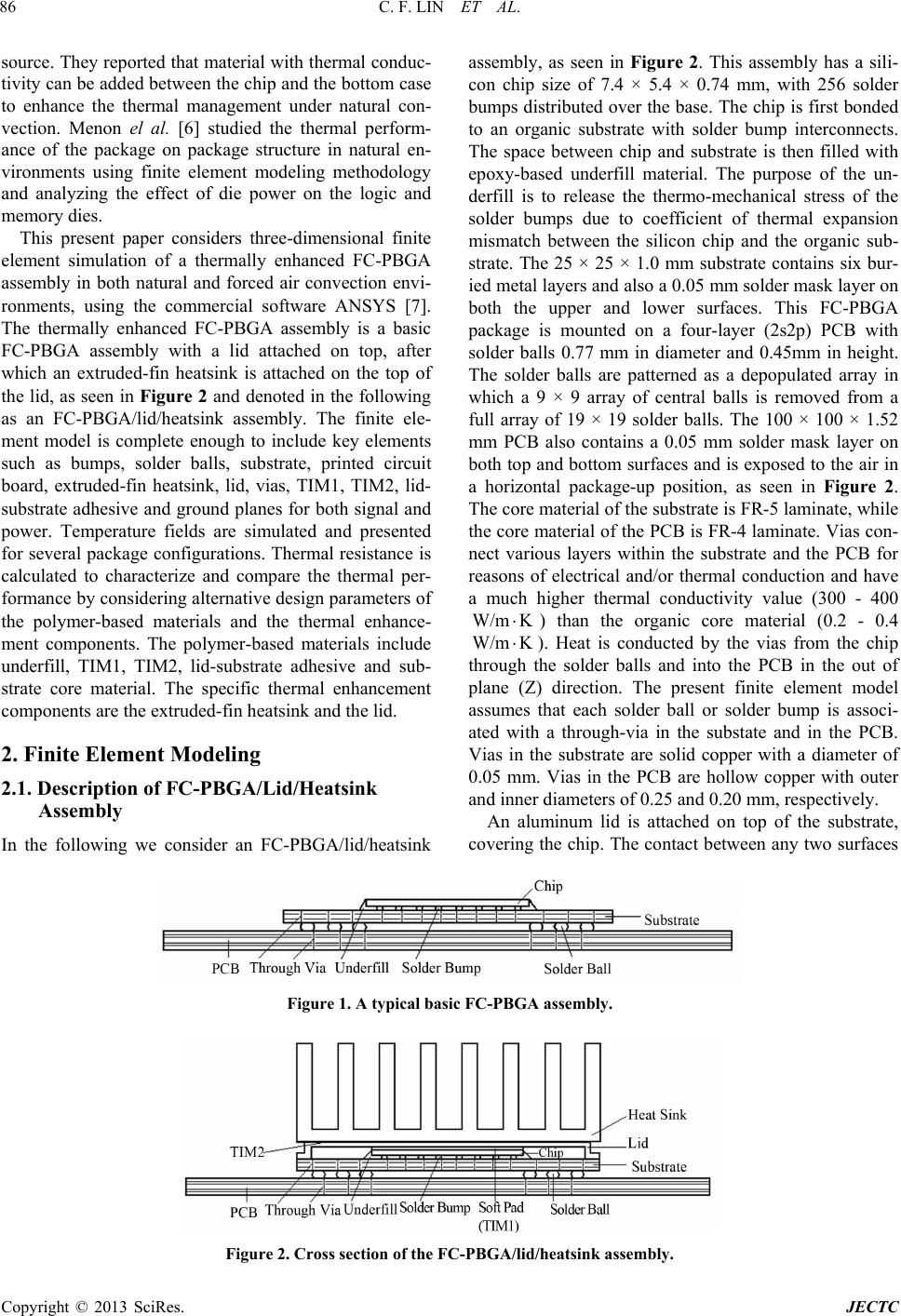 C. F. LIN ET AL. 86 source. They reported that material with thermal conduc- tivity can be added between the chip and the bottom case to enhance the thermal management under natural con- vection. Menon el al. [6] studied the thermal perform- ance of the package on package structure in natural en- vironments using finite element modeling methodology and analyzing the effect of die power on the logic and memory dies. This present paper considers three-dimensional finite element simulation of a thermally enhanced FC-PBGA assembly in both natural and forced air convection envi- ronments, using the commercial software ANSYS [7]. The thermally enhanced FC-PBGA assembly is a basic FC-PBGA assembly with a lid attached on top, after which an extruded-fin heatsink is attached on the top of the lid, as seen in Figure 2 and denoted in the following as an FC-PBGA/lid/heatsink assembly. The finite ele- ment model is complete enough to include key elements such as bumps, solder balls, substrate, printed circuit board, extruded-fin heatsink, lid, vias, TIM1, TIM2, lid- substrate adhesive and ground planes for both signal and power. Temperature fields are simulated and presented for several package configurations. Thermal resistance is calculated to characterize and compare the thermal per- formance by considering alternative design parameters of the polymer-based materials and the thermal enhance- ment components. The polymer-based materials include underfill, TIM1, TIM2, lid-substrate adhesive and sub- strate core material. The specific thermal enhancement components are the extruded-fin heatsink and the lid. 2. Finite Element Modeling 2.1. Description of FC-PBGA/Lid/Heatsink Assembly In the following we consider an FC-PBGA/lid/heatsink assembly, as seen in Figure 2. This assembly has a sili- con chip size of 7.4 × 5.4 × 0.74 mm, with 256 solder bumps distributed over the base. The chip is first bonded to an organic substrate with solder bump interconnects. The space between chip and substrate is then filled with epoxy-based underfill material. The purpose of the un- derfill is to release the thermo-mechanical stress of the solder bumps due to coefficient of thermal expansion mismatch between the silicon chip and the organic sub- strate. The 25 × 25 × 1.0 mm substrate contains six bur- ied metal layers and also a 0.05 mm solder mask layer o n both the upper and lower surfaces. This FC-PBGA package is mounted on a four-layer (2s2p) PCB with solder balls 0.77 mm in diameter and 0.45mm in height. The solder balls are patterned as a depopulated array in which a 9 × 9 array of central balls is removed from a full array of 19 × 19 solder balls. The 100 × 100 × 1.52 mm PCB also contains a 0.05 mm solder mask layer on both top and botto m surfaces and is exposed to the air in a horizontal package-up position, as seen in Figure 2. The core material of the substrate is FR-5 laminate, while the core material of the PCB is FR-4 laminate. Vias con- nect various layers within the substrate and the PCB for reasons of electrical and/or thermal conduction and have a much higher thermal conductivity value (300 - 400 W/m K ) than the organic core material (0.2 - 0.4 W/m K ). Heat is conducted by the vias from the chip through the solder balls and into the PCB in the out of plane (Z) direction. The present finite element model assumes that each solder ball or solder bump is associ- ated with a through-via in the substate and in the PCB. Vias in the substrate are solid copper with a diameter of 0.05 mm. Vias in the PCB are hollow copper with outer and inner diameters of 0.25 and 0.20 mm, respectively. An aluminum lid is attached on top of the substrate, covering the chip. The contact b etween any two surfaces Figure 1. A typical basic FC-PBGA assembly. Figure 2. Cross section of the FC-PBGA/lid/heatsink assembly. Copyright © 2013 SciRes. JECTC 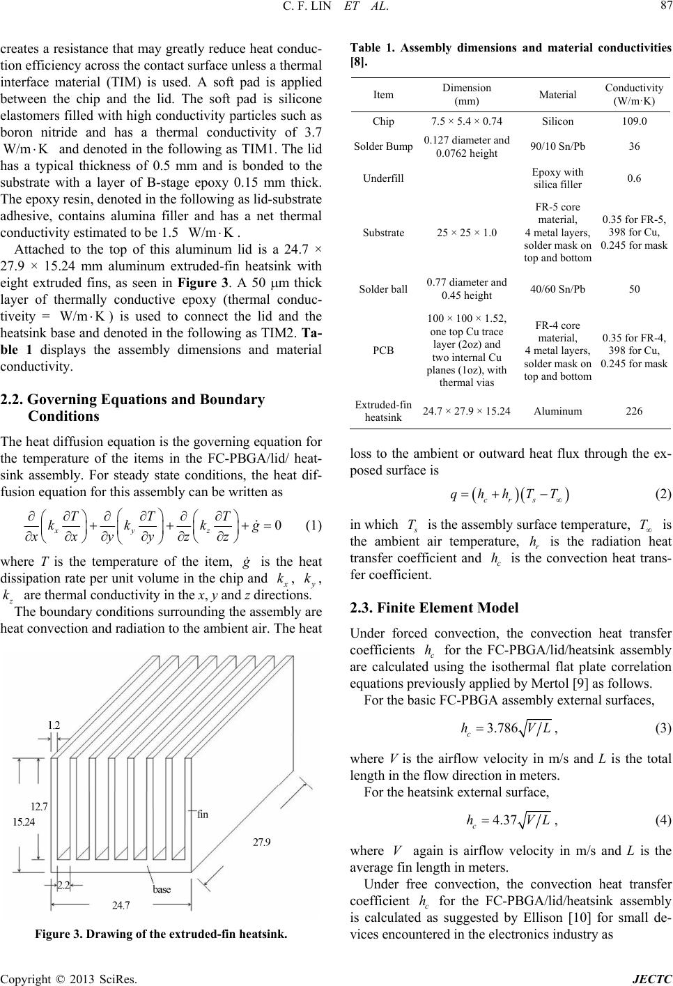 C. F. LIN ET AL. 87 creates a resistance that may greatly reduce heat conduc- tion efficiency across the contact surface unless a thermal interface material (TIM) is used. A soft pad is applied between the chip and the lid. The soft pad is silicone elastomers filled with high conductivity particles such as boron nitride and has a thermal conductivity of 3.7 and denoted in the following as TIM1. The lid has a typical thickness of 0.5 mm and is bonded to the substrate with a layer of B-stage epoxy 0.15 mm thick. The epoxy resin, deno ted in the fo llowin g as lid-sub strate adhesive, contains alumina filler and has a net thermal conductivity estimated to be 1.5 . W/m K W/m K Attached to the top of this aluminum lid is a 24.7 × 27.9 × 15.24 mm aluminum extruded-fin heatsink with eight extruded fins, as seen in Figure 3. A 50 m thick layer of thermally conductive epoxy (thermal conduc- tiveity = ) is used to connect the lid and the heatsink base and denoted in th e following as TIM2. Ta- ble 1 displays the assembly dimensions and material conductivity. W/m K 2.2. Governing Equations and Boundary Conditions The heat diffusion equation is the governing equation for the temperature of the items in the FC-PBGA/lid/ heat- sink assembly. For steady state conditions, the heat dif- fusion equation for this assembly can be written as 0 xyz TTT kkk xxyyzz g (1) where T is the temperature of the item, g is the heat dissipation rate per unit volume in the chip and x k, y k, z k are thermal conductivity in the x, y and z directions. The boundary conditions surrounding the assembly are heat convection and radiation to the ambient air. The heat Figure 3. Drawing of the extrude d-fin heatsink. Table 1. Assembly dimensions and material conductivities [8]. Item Dimension (mm) Material Conductivity (W/m·K) Chip 7.5 × 5.4 × 0.74 Silicon 109.0 Solder Bump0.127 diameter and 0.0762 height 90/10 Sn/Pb 36 Underfill Epoxy with silica filler 0.6 Substrate 25 × 25 × 1.0 FR-5 core material, 4 metal layers, solder mask on top and bottom 0.35 for FR-5, 398 for Cu, 0.245 for mask Solder ball0.77 diameter and 0.45 height 40/60 Sn/Pb 50 PCB 100 × 100 × 1.52, one top Cu trace layer (2oz) and two internal Cu planes (1oz), with thermal vias FR-4 core material, 4 metal layers, solder mask on top and bottom 0.35 for FR-4, 398 for Cu, 0.245 for mask Extruded-fin heatsink 24.7 × 27.9 × 15.24 Aluminum 226 loss to the ambient or outward heat flux through the ex- posed surface is crs qhhTT (2) in which s T is the assembly surface temperature, T is the ambient air temperature, r is the radiation heat transfer coefficient and is the convection heat trans- fer coefficient. h c h 2.3. Finite Element Model Under forced convection, the convection heat transfer coefficients c for the FC-PBGA/lid/heatsink assembly are calculated using the isothermal flat plate correlation equations previously applied by Mertol [9] as follows. h For the basic FC-PBGA assembly external surfaces, 3.786 c hVL, (3) where V is the airflow velocity in m/s and L is the total length in the flow direction in meters. For the heatsink external surface, 4.37 c hVL, (4) where again is airflow velocity in m/s and L is the average fin length in meters. V Under free convection, the convection heat transfer coefficient c for the FC-PBGA/lid/heatsink assembly is calculated as suggested by Ellison [10] for small de- vices encountered in the electronics industry as h Copyright © 2013 SciRes. JECTC 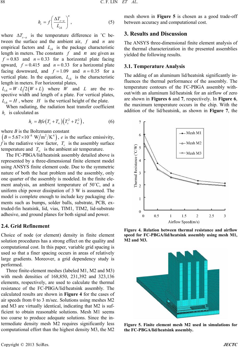 C. F. LIN ET AL. 88 n sa cch T hfL , (5) where s a is the temperature difference in ˚C be- tween the surface and the ambient air, T f and are empirical factors and ch is the package characteristic length in meters. The constants n L f and are given as and for a horizontal plate facing upward, and for a horizontal plate facing downward, and and for a vertical plate. In the equation, ch is the characteristic length in meters. For horizontal plates, n n 0.83 f f0.33 n f n 0.415 0.33 09 L 1.0.35 2 ch where and are the re- spective width and length of a plate. For vertical plates, , where LW ch LH LWLWL H is the vertical height of the plate. When radiating, the radiation heat transfer coefficient is calculated as r h 22 rss hBfeTTTT , (6) where B is the Boltzmann constant 82 5.6710W mKB 4 , e is the surface emissivity, f is the radiative view factor, s T is the assembly surface temperature and is the ambient air temperature. T The FC-PBGA/lid/heatsink assembly detailed above is represented by a three-dimensional finite element model using ANSYS finite element code. Due to the symmetric nature of both the heat problem and the assembly, only one quarter of the assembly is modeled. In the finite ele- ment analysis, an ambient temperature of 50˚C, and a uniform chip power dissipation of 3 W is assumed. The model is complete enough to include key packaging ele- ments such as bumps, solder balls, substrate, PCB, ex- truded-fin heatsink, lid, vias, TIM1, TIM2, lid-substrate adhesive, and ground planes for both signal and power. 2.4. Grid Refinement Choice of node (or element) density in finite element solution procedures has a strong effect on the quality and computational cost. In this paper, variable grid spacing is used so that a finer spacing occurs in areas of relatively large gradients. Moreover, a grid dependency study is performed. Three finite-element meshes (labeled M1, M2 and M3) with mesh densities of 168,850, 231,392 and 323,136 elements, respectively, are used to calculate the thermal resistance of the FC-PBGA/lid/heatsink assembly. The calculated results are shown in Figure 4 for the cases of air speeds from 0 to 3 m/sec. Solu tions using meshes M2 and M3 are virtually identical, indicating that M2 is suf- ficient to obtain reasonable solutions. Mesh M1 seems too coarse to produce adequate solutions. Since the in- termediate density mesh M2 requires significantly less computational effort than the highest density M3, the M2 mesh shown in Figure 5 is chosen as a good trade-off between accuracy and computational cost. 3. Results and Discussion The ANSYS three-dimensional finite element analysis of the thermal characterization in the presented assemblies yielded the following results. 3.1. Temperature Analysis The adding of an aluminum lid/heatsink significantly in- fluences the thermal performance of the assembly. The temperature contours of the FC-PBGA assembly with- out/with an aluminum lid/heatsink for an airflow of zero are shown in Figures 6 and 7, respectively. In Figure 6, the maximum temperature occurs in the chip. With the addition of the lid/heatsink, as shown in Figure 7, the Figure 4. Relation between thermal resistance and airflow speed for FC-PBGA/lid/heatsink assembly using mesh M1, M2 and M3. Figure 5. Finite element mesh M2 used in simulations for the FC-PBGA/lid/heatsink assembly. Copyright © 2013 SciRes. JECTC  C. F. LIN ET AL. 89 Figure 6. Temperature contours for the basic FC-PBGA as- sembly at airflow = zero. Figure 7. Temperature contours for the FC-PBGA/lid/heat- sink assembly at airflow = zero. maximum temperature still occurs in the chip. However, the maximum temperatures drop significantly. The tem- perature contours of the extruded-fin heatsink are shown in Figure 8, where the maximum temperature is found at the bottom center (remembering that the figure shows only one quarter of the extruded-fin heatsink since the total assembly is symmetrical), while the minimum tem- perature occurs at the outside corner of the most distant fin’s upper edge. The temperature distribution in the ex- truded-fin heatsink is quite uniform due to the very high thermal conductivity of the aluminum material. 3.2. Thermal Resistance As commonly done, thermal resistance j a R is used to characterize the thermal performance of an assembly, defined as j ja TT RP (7) where j T is the predicted maximum temperature for the assembly, P the device power and is the ambient air temperature. T Figure 8. Temperature distribution for the extruded-fin heatsink at airflow = zero. For comparison of thermal performance, four different FC-PBGA assembly versions are considered in this sec- tion and described as follows: 1) The basic FC-PBGA assembly (or the basic FC- PBGA model), defined as the FC-PBGA assembly with- out thermal enhancement shown in Figure 1; 2) Basic FC-PBGA model + lid, defined as the basic assembly with a lid attached on the top; 3) Basic FC-PBGA model + heatsink, defined as the basic assembly with a extruded-fin heatsink attached on the top; 4) Basic FC-PBGA model + lid/heatsink, defined as the basic assembly with a lid attached on top, after which extruded-fin heatsink is attached on the top of the lid (i.e. FC-PBGA/lid/heatsink shown in Figure 2). Figure 9 shows the thermal performance of the above four cases for airflows ranging from 0 to 3 m/sec. Addi- tion of the lid to the basic FC-PBGA model (i.e. basic FC-PBGA model + lid) causes significant improvement in thermal performance. The high thermal conductivity of the aluminum lid results in a larger surface area with a temperature high enough for good convective cooling. Addition of only the extruded-fin heatsink to the basic model (i.e. basic FC-PBGA model + heatsink) causes large improvement in thermal performance relative to the basic FC-PBGA model due to the large increase in heat transfer area. Addition of the lid between the basic FC- PBGA model and the extruded-fin heatsink (i.e. basic FC-PBGA model + lid/heatsink or FC-PBGA/lid/heatsink) results in a small further improvement in thermal per- formance. This small further increase can be attributed to the increased cooling area made available by the sides of the lid. Clearly, the increased cooling area presented by the sides of lid is small relative to the large total cooling area of the extruded-fin heatsink. The role of the lid is interesting. If a extruded-fin heatsink is not applied to the basic model, then addition of the lid results in significant Copyright © 2013 SciRes. JECTC  C. F. LIN ET AL. 90 improvement of thermal performance. On the other hand, if a extruded-fin heatsink has been applied to the basic FC-PBGA model, then the further addition of the lid does not result in significant further improvement of thermal performance. Inspection of Figure 9 shows that, at an airflow of zero, the predicted j a of the FC-PBGA/lid/heatsink is about 57.0% lower than the basic PBGA assembly. If progressively faster air flow is applied to the FC-PBGA/ lid/heatsink, then the improvement of the FC-PBGA/lid/ heatsink relative to the basic FC-PBGA assembly at air- flow = zero increases with increasing air speed, reaching a maximum improvement of 84.9% at this study’s maximum airspeed of 3 m/s. R 3.3. Effects of Design Parameters Thermal performance is analyzed by considering various design parameters of the polymer-based materials and the thermal enhancement components. The polymer-based materials include underfill, TIM1, TIM2, lid-substrate adhesive and substrate core material. The specific ther- mal enhancement components are the lid and the ex- truded-fin heatsink. Effects of the design parameters are studied by varying the parameter values by 30% for all material conductivities and by 15% for all material di- mensions in both natural and forced convection environments. Simulation results are shown in Figures 10-13. 0v 1v Figure 9. Relation between thermal resistance and airflow speed for four different assembly configur ations. Figure 10. Relation between thermal resistance and thermal conductivity in natural convection condition 0v . Figure 11. Relation between thermal resistance and thermal conductivity in forced convection condition . 1v 3.3.1. Effect of Extruded-Fin Heatsink Extruded-fin heatsink design has significant effect on thermal performance of the assembly. The effects of ex- truded-fin heatsink conductivity with regard to thermal performance of the assembly can be found in Figures 10 and 11 for both natural and forced convection environ- ments, respectively. Increased extruded-fin heatsink conductivity increases the thermal performance of the assembly since higher thermal conductivity improves the heat spreading effect in the heatsink. Figure 14 further shows the thermal resistance j a vs the thermal con- ductivity of the extruded-fin heatsink for airflows rang- ing from 0 to 3 m/sec. The results show little improve- ment in performance at thermal conductivities above R 200 WmK . Thus, little advantage can be obtained by using copper (thermal conductivity = 393 W/m·K) rela- tive to aluminum (thermal conductivity = 226 W/m·K). Copyright © 2013 SciRes. JECTC  C. F. LIN ET AL. 91 Figure 12. Relation between thermal resistance and dimen- sions in natural convection condition . 0v Figure 13. Relation between thermal resistance and dimen- sions in forced convection condition . 1v Figure 14. Relation between thermal resistance and extru- ded-fin heatsink conductivity. This observation is of interest to designers with regard to material selection. Effects of fin length, fin thickness, fin number and base thickness of the extruded-fin heatsink on thermal resis- tance j a are presented for the FC-PBGA/lid/heatsink assembly. Increasing the number of fins or the length of the fins decreases the thermal resistance R j a due to the increase of heatsink cooling area, as shown in Figures 15 and 16 , for both natural R 0v and forced convection 1v environments. It is seen that j a improves as the base thickness in- creases because increased base thickness increases the total cooling area of the heatsink and improves the cool- ing efficiency of the heatsink. But the improvement is small and the resulting material cost could be higher. R Figure 15. Relation between thermal resistance and design parameters of extruded-fin heatsink in natural convection condition 0v . Figure 16. Relation between thermal resistance and design parameters of extruded-fin heatsink in forced convection condition 1v . Copyright © 2013 SciRes. JECTC  C. F. LIN ET AL. 92 Increasi fing the n thickness increases the total cooling ar rotect the chip and improve heat ea of the heatsink. However this increased cooling area is very small compared with the total area of the heat- sink, so the results show only a slight effect for fin thick- ness and can be neglected. 3.3.2. Effect of the Lid The purpose of lid is to p spreading from the chip. Effect of thermal conductivity of the lid on the thermal performance of the assembly for both natural and forced convection environments can also be found in Figures 10 and 11, respectively. In- creased lid conductivity increases the thermal perform- ance of the assembly. Specific variance of the thermal resistance j a R 2 a rela- tive to the lid thickness is shown in Figures 1nd 13 for both natural and forced convection environments. The results shows a small improvement in j a R as thick- ness increases. 3.3.3. Effect of Underfill fill is to release the thermo- M2 the thermal perform- the substrate e assembly due to a longer thermal path fo ffect of Lid-Substrate Adhesive An adhesive material is required to form a good bond cts of the con- finite element simulation has been thermal performance of a thermally gn parameters of the polymer- ba mal performance of the assembly. High er ther- m The purpose of the under mechanical stress of the solder bumps due to CTE mis- match between the silicon chip and the organic substrate. Increased thermal conductivity of the underfill increases the heat conduction in the package and is helpful for dis- sipating heat to the ambient atmosphere. Thus, increasing the conductivity of the underfill increases the thermal performance of the assembly. 3.3.4. Effect of TIM1 and TI The effects of TIM1 and TIM2 on ance of the asse mbly for both natura l and forced convec- tion environments can also be found in Figures 10-13. As TIM1’s or TIM2’s conductivity incr eases, the ther- mal performance of the assembly increases, since in- creased conductivity of TIM1 or TIM2 reduces the ther- mal resistance in the heat transfer path. Also, it can be found in Figures 12 and 13 that as TIM1’s or TIM2’s thickness decreases, the thermal performance of the as- sembly increases, since decreased thickness of TIM1 or TIM2 reduces the thermal resistance in the heat transfer path. Simulation results show that TIM1 has a greater influence on assembly thermal performance than TIM2. 3.3.5. Effect of Substrate Core Material The effect of the thermal conductivity of core material on the thermal performance of the assem- bly can also be found in Figures 10 and 11. Increasing the conductivity of the substrate core material increases heat transfer from chip to ambient, but the amount of heat conducted through this pathway is quite small rela- tive to the amount conducted through the vias and heat- sink. Thus, thermal performance increases with increas- ing conductivity of the substrate core material, but the effect is small. Thicker substrate core material reduces the thermal performance of th r heat transfer to the PCB. Thus thermal performance decreases with increasing thickness of the substrate core material but the effect is small, as seen in Figures 12 and 13. 3.3.6. E between the lid and the substrate. The effe ductivity and thickness of the adhesive with regard to the thermal performance of the assembly are also shown in Figures 10-13. It is found that these effects are all rela- tively insignificant, but higher conductivity and smaller thickness are preferred. 4. Conclusions Three-dimensional used to study the enhanced FC-PBGA assembly in both natural and forced air convection environments. The thermally enhanced FC-PBGA assembly is a basic FC-PBGA assembly with a lid attached on top, after which an extruded-fin heat- sink is attached on the top of the lid. The adding of an aluminum lid/heatsink significantly influences the ther- mal performance of the assembly due to the large in- crease in heat transfer area. Also, the temperature dis- tribution in the extruded-fin heatsink is quite uniform due to the very high thermal conductivity of the aluminum material. If a extruded-fin heatsink is not applied to the basic model, then addition of the lid results in significant improvement of the thermal performance. On the other hand, if an extruded-fin heatsink has been applied to the basic model, then further addition of the lid does not re- sult in significant further improvement of thermal per- formance, because the increased cooling area presented by the sides of lid is little relative to the large total cool- ing area of the heatsink. A series of parametric simulations investigate the ef- fects of varying the desi sed materials and the thermal enhancement compo- nents. Conclusions from the analysis are summarized as follows: 1) Extruded-fin heatsink design has significant effects on the ther al conductivity improves the thermal performance of the assembly. However, results show little improvement in performance at thermal conductivities above 200 W/m·K. Thus, little advantage can be obtained by using copper (thermal conductivity = 393 W/m·K) relative to aluminum (thermal conductivity = 226 W/m·K). This observation is of interest to designers with regard to ma- Copyright © 2013 SciRes. JECTC  C. F. LIN ET AL. Copyright © 2013 SciRes. JECTC 93 or TIM2 decreases, the thermal pe s but the improve- m ce of the assembly increa- se nd to have lesser impact o pa FERENCES [1] G. H. Wu, S.HThree-Dimensional Finite Elemenechanical Behavior terial selection. Increasing the fin length, fin number, and base thickness of the extruded-fin heatsink results in in- creased thermal performance of the assembly. For the cases studied, simulation results show that the fin length and fin number have a stronger influence on the thermal performance than base thickness. The effect of fin thick- ness is negligibly small. 2) As for conductivity, when TIM1 or TIM2 increases or the thickn ess of TIM1 rformance of the assembly increases. Simulation re- sults show that TIM1 has a stronger influence on assem- bly thermal performance than TIM2. 3) As conductivity of the underfill increases, thermal performance of the assembly increase ent is not very significant. 4) It is found that as the thickness of the substrate core decreases, thermal performan s. Thermal performance of the assembly can be en- hanced by using a thinner core. Also, higher conductivity of the substrate core is desirable for better thermal per- formance of the assembly. 5) The effects of the lid-substrate adhesive parameters are also considered and foun ckage thermal performance. However, higher conduc- tivity and lower thickness of the lid-substrate adhesive are found preferable. RE . Ju and T. C. Tsein, “ t Analysis of Thermom in Flip-Chip Packages under Temperature Cycling Condi- tions,” Journal of Reinforced Plastics and Composites, Vol. 24, No. 18, 2005, pp. 1895-1907. doi:10.1177/0731684405054333 [2] F. Gugliermermetti and S. Grignaffini, “Direct Approach Thermal performance of Flip Chip Ball Grid hiang, “Thermal to the Design of Plate Fin Heat Sinks Stack Cooled by Forced Convection,” IEEE Electronic Packaging Tech- nology Conference, San Diego, 8-10 December 1998, pp. 138-142. [3] B. Joiner, “ Arrays Packages,” Eighteenth Annual IEEE Semiconduc- tor Thermal Measurement and Management Symposium, San Jose, 12-14 March 2002, pp. 50-56. [4] K. M. Chen, K. H. Houng and K. N. C Resistance Analysis and Validation of Flip Chip PBGA Packages,” Microelectronics Reliability, Vol. 46, No. 2-4, 2006, pp. 440-448. doi:10.1016/j.microrel.2005.06.001 [5] Z. Luo, H. Cho and K. Cho, “System Thermal Analysis of Mobile Phone,” Applied Thermal Engineering, Vol. 28, No. 14-15, 2008, pp. 1889-1895. doi:10.1016/j.applthermaleng.2007.11.025 [6] A. R. Menon, S. Karajgikar and D. Agonafer, “Thermal evision 13.0,” Swanson Ana- ermal Enhancement on Design Optimization of a Package on Package,” 25th Annual IEEE Semiconductor Thermal Measurement and Management Symposium (Semi-Therm), San Jose, 15-19 March 2009, pp. 329-336. [7] “ANSYS User’s Manual, R lysis System Inc., Houston, 2010. [8] T.-Y. Lee, “An Investigation of Th Flip Chip Plastic BGA Packages Using CFD Tool,” IEEE Transactions on Components, Packaging, and Manufac- turing Technology, Vol. 23, No. 3, 2000, pp. 481-489. doi:10.1109/6144.868847 [9] A. Mertol, “Thermal Performance Comparison of High tations for Electronic Equip- omenclature Pin Count Cavity-Up Enhanced Plastic Ball Grid Array (EPBGA) Packages,” IEEE Transactions on Components, Packaging, and Manufacturing Technology, Part B, Vol. 19, No. 2, 1996, pp. 427-443. [10] G. N. Ellison, “Thermal Compu ment,” E. Robert Krieger Publishing Company, Malabar, 1989. Nn: empirical factor. P:it bd. device power, W. f : empirical factor. ll grid array. PCB: printed circuoar FC-PBGA: flip-chip plastic ba s a T : temperature difference between the surface and g : heat dissipation rate per unit volume in the chip, the ambient air, ˚C. T : ambient air tem 3. Wm kperature, ˚C. : thermal conductivity, WmK. x k: thermal conductivity in the x direction, WmK . y k: thermal conductivity in the y direction, WmK . z k: thermal conductivity in the z direction, WmK . c h: convection heat transfer coefficient, 2 Wm K . rad : radiation heat transfer coefficient, h2 Wm K . ch L: characteristic length, m. j a T: R: thermal resistance of the assembly, ˚C/W. temperature, ˚C. j T C. : predicted maximum temperature of an assembly, ˚: surface temperature of the assembly, ˚C. s T V: air velocity, m/s. |