

Paper Menu >>
Journal Menu >>
 Journal of Sensor Technology, 2013, 3, 36-41 http://dx.doi.org/10.4236/jst.2013.33007 Published Online September 2013 (http://www.scirp.org/journal/jst) Conducting Rubber Force Sensor: Transient Characteristics and Radiation Heating Effect Masato Ohmukai1, Yasushi Kami1, Ken Ashida2 1Department of Electrical and Computer Engineering, Akashi College of Technology, Akashi, Japan 2Department of System Science, School of Engineering Science, Osaka University, Toyonaka, Japan Email: [email protected] Received May 20, 2013; revised June 20, 2013; accepted June 28, 2013 Copyright © 2013 Masato Ohmukai et al. This is an open access article distributed under the Creative Commons Attribution License, which permits unrestricted use, distribution, and reproduction in any medium, provided the original work is properly cited. ABSTRACT Compression force sensors are indispensable to tactile sensors in humanoid robots. We are investigating the application of low-cost electrically conducting rubber sheets to force sensors, of which the biggest problem is its poor reproducibil- ity. We have found that the deposition of aluminum by a vacuum evaporation method shows such an excellent charac- teristic that the sensor can be used in a wide range under 10.33 N/cm2. In this article, we investigated time response of the sensors and also studied how the radiation heating during the vacuum evaporation process for Al deposition affected their sensing property. We found that the radiation heating induces deterioration from the point of view of standard de- viation of the output voltage of the sensors at a transient region. We convince that a low-temperature Al deposition method should be developed to form electrodes on the electrical conducting rubber sensors. Keywords: Conducting Rubber; Force Sensor; Electrode; Vacuum Deposition; Radiation Heating 1. Introduction Along with the development of humanoid robots, force sensors play a key role in controlling the actuation of robot fingers [1]. In order to realize the elaborate function of robot fingers, we need a sophisticated control system. Even with a highly designed control system, a highly reproducible force sensor is crucial for good control be- cause the tactile information is used as control parame- ters in dexterous manipulation of humanoid fingers [2-4]. The studies on tactile sensors have been fully reported so far. The types of the sensors are ranged in a wide vari- ety. A kind of them is typically based on a strain gauge or a piezoresistive device. The resistance variation is brought about by the applied strain in these devices. The sensor arrays of this type have been reported nowadays [5-7]. The arrays of micro sensors demonstrated the abil- ity in position sensing. In some cases, micro-machine technique was included to form this kind of sophisticated sensors. Some researchers have studied three-dimension sensor arrays that can detect shear forces [8]. Many other sensors of different types have been reported widely [9-29]. In order to miniature the sensing system, silicon- based microelectromechanical system (MEMS) has been challengingly applied [30,31] to piezoresistive [32-35] or capacitive [36,37] type of tactile sensors. We pay attention to a conductive rubber sheet that varies electric resistance with compressive force. The conductive rubber consists of an elastomer enriched with conductive filler particles. The resistance of the rubber sheet reduces when external compressive pressure is ap- plied. The material shows isotropic conduction. The ad- vantage of the rubber sheet as a force sensor is the low cost of the flexible material as well as the large area sen- sing ability. In order to deal successfully with the short of reliability of the material, it still requires more improve- ments in the fabrication of this sensor. The formation of electrodes on the rubber surfaces comes into an issue at first. Electrodes are a basic component of electric devices but the issue has not been examined so far. We investigated the rubber sensors with four kinds of electrodes in our previous work: Al thin film, Al depos- ited on the rubber sheet by a vacuum deposition method, conducting adhesive Cu tape and silver paste spread on the surfaces. The relationship of the resistance to applied force has been studied and discussed from the point of view of a force sensor in a robotic finger. Then we have concluded that the Al deposition in vacuum is the most preferable with regard to a force range and reproducibil- ity [38]. However, we concerned the deterioration in- duced by the radiation heating during the vacuum depo- sition because the rubber sheet was installed very near to C opyright © 2013 SciRes. JST 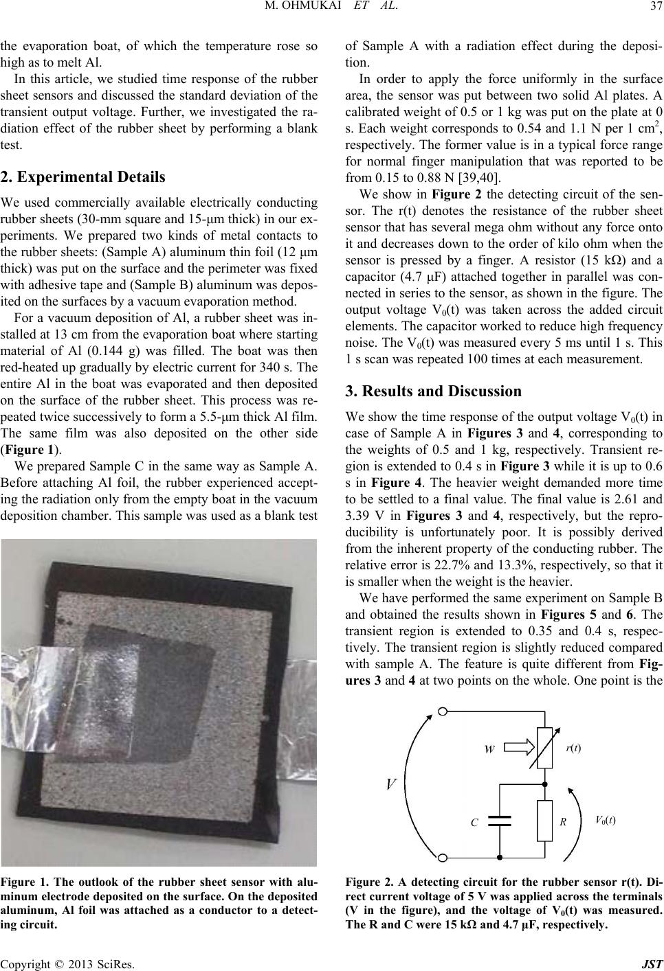 M. OHMUKAI ET AL. 37 the evaporation boat, of which the temperature rose so high as to melt Al. In this article, we studied time response of the rubber sheet sensors and discussed the standard deviation of the transient output voltage. Further, we investigated the ra- diation effect of the rubber sheet by performing a blank test. 2. Experimental Details We used commercially available electrically conducting rubber sheets (30-mm square and 15-μm thick) in our ex- periments. We prepared two kinds of metal contacts to the rubber sheets: (Sample A) aluminum thin foil (12 μm thick) was put on the surface and the perimeter was fixed with adhesive tape and (Sample B) aluminum was depos- ited on the surfaces by a vacuum evaporation method. For a vacuum deposition of Al, a rubber sheet was in- stalled at 13 cm from the evaporation boat where starting material of Al (0.144 g) was filled. The boat was then red-heated up gradually by electric current for 340 s. The entire Al in the boat was evaporated and then deposited on the surface of the rubber sheet. This process was re- peated twice successively to form a 5.5-μm thick Al film. The same film was also deposited on the other side (Figure 1). We prepared Sample C in the same way as Sample A. Before attaching Al foil, the rubber experienced accept- ing the radiation only from the empty boat in the vacuum deposition chamber. This sample was used as a blank test Figure 1. The outlook of the rubber sheet sensor with alu- minum electrode deposited on the surface. On the deposited aluminum, Al foil was attached as a conductor to a detect- ing circuit. of Sample A with a radiation effect during the deposi- tion. In order to apply the force uniformly in the surface area, the sensor was put between two solid Al plates. A calibrated weight of 0.5 or 1 kg was put on the plate at 0 s. Each weight corresponds to 0.54 and 1.1 N per 1 cm2, respectively. The former value is in a typical force range for normal finger manipulation that was reported to be from 0.15 to 0.88 N [39,40]. We show in Figure 2 the detecting circuit of the sen- sor. The r(t) denotes the resistance of the rubber sheet sensor that has several mega ohm without any force onto it and decreases down to the order of kilo ohm when the sensor is pressed by a finger. A resistor (15 kΩ) and a capacitor (4.7 μF) attached together in parallel was con- nected in series to the sensor, as shown in the figure. The output voltage V0(t) was taken across the added circuit elements. The capacitor worked to reduce high frequency noise. The V0(t) was measured every 5 ms until 1 s. This 1 s scan was repeated 100 times at each measurement. 3. Results and Discussion We show the time response of the output voltage V0(t) in case of Sample A in Figures 3 and 4, corresponding to the weights of 0.5 and 1 kg, respectively. Transient re- gion is extended to 0.4 s in Figure 3 while it is up to 0.6 s in Figure 4. The heavier weight demanded more time to be settled to a final value. The final value is 2.61 and 3.39 V in Figures 3 and 4, respectively, but the repro- ducibility is unfortunately poor. It is possibly derived from the inherent property of the conducting rubber. The relative error is 22.7% and 13.3%, respectively, so that it is smaller when the weight is the heavier. We have performed the same experiment on Sample B and obtained the results shown in Figures 5 and 6. The transient region is extended to 0.35 and 0.4 s, respec- tively. The transient region is slightly reduced compared with sample A. The feature is quite different from Fig- ures 3 and 4 at two points on the whole. One point is the C r(t) V0(t) R Figure 2. A detecting circuit for the rubber sensor r(t). Di- rect current voltage of 5 V was applied across the terminals (V in the figure), and the voltage of V0(t) was measured. The R and C were 15 kΩ and 4.7 μF, respectively. Copyright © 2013 SciRes. JST 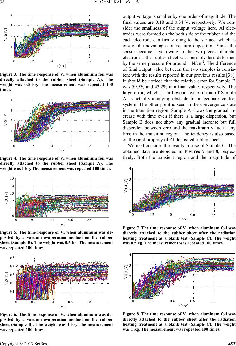 M. OHMUKAI ET AL. 38 0 0.2 0.4 0.6 0.8 1 t [sec] 4 3 2 1 0 V0(t) [V] Figure 3. The time response of V0 when aluminum foil was directly attached to the rubber sheet (Sample A). The weight was 0.5 kg. The measurement was repeated 100 times. 0 0.2 0.4 0.6 0.8 1 t [sec] 4 3 2 1 0 V0(t) [V] Figure 4. The time response of V0 when aluminum foil was directly attached to the rubber sheet (Sample A). The weight was 1 kg. The measurement was repeated 100 times. 0 0.2 0.4 0.6 0.8 1 t [sec] 0.5 0.4 0.3 0.2 0.1 0 V0(t) [V] Figure 5. The time response of V0 when aluminum was de- posited by a vacuum evaporation method on the rubber sheet (Sample B). The weight was 0.5 kg. The measurement was repeated 100 times. 0 0.2 0.4 0.6 0.8 1 t [sec] 0.5 0.4 0.3 0.2 0.1 0 V0(t) [V] Figure 6. The time response of V0 when aluminum was de- posited by a vacuum evaporation method on the rubber sheet (Sample B). The weight was 1 kg. The measurement was repeated 100 times. output voltage is smaller by one order of magnitude. The final values are 0.18 and 0.34 V, respectively. We con- sider the smallness of the output voltage here. Al elec- trodes were formed on the both side of the rubber and the each electrode can firmly cling to the surface, which is one of the advantages of vacuum deposition. Since the sensor became rigid owing to the two pieces of metal electrodes, the rubber sheet was possibly less deformed by the same pressure for around 1 N/cm2. The difference of final output value between the two samples is consis- tent with the results reported in our previous results [38]. It should be noticed that the relative error for Sample B was 59.5% and 43.2% in a final value, respectively. The large error, which is far beyond twice of that of Sample A, is actually annoying obstacle for a feedback control system. The other point is seen in the convergence state in the transition region. Sample A shows the gradual in- crease with time even if there is a large dispersion, but Sample B does not show any gradual increase but full dispersion between zero and the maximum value at any time in the transition region. The tendency is also based on the rigid property of Al deposited rubber sheets. We next consider the results in case of Sample C. The obtained data are depicted in Figures 7 and 8, respec- tively. Both the transient region and the magnitude of 0 0.2 0.4 0.6 0.8 1 t [sec] 4 3 2 1 0 V0(t) [V] Figure 7. The time response of V0 when aluminum foil was directly attached to the rubber sheet after the radiation heating treatment as a blank test (Sample C). The weight was 0.5 kg. The measurement was repeated 100 times. 0 0.2 0.4 0.6 0.8 1 t [sec] 4 3 2 1 0 V0(t) [V] Figure 8. The time response of V0 when aluminum foil was directly attached to the rubber sheet after the radiation heating treatment as a blank test (Sample C). The weight was 1 kg. The measurement was repeated 100 times. Copyright © 2013 SciRes. JST 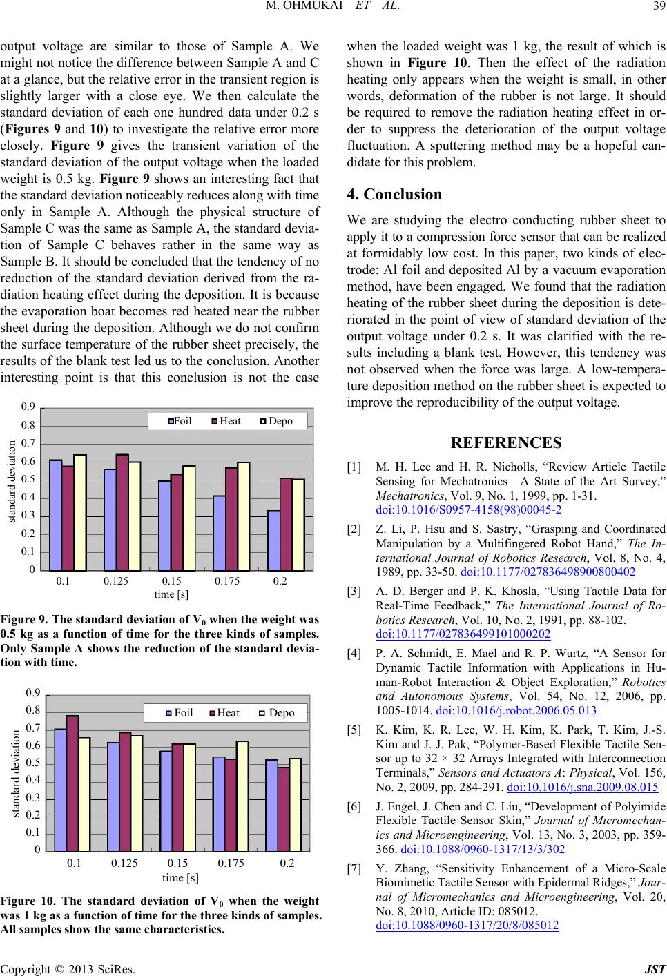 M. OHMUKAI ET AL. 39 output voltage are similar to those of Sample A. We might not notice the difference between Sample A and C at a glance, but the relative error in the transient region is slightly larger with a close eye. We then calculate the standard deviation of each one hundred data under 0.2 s (Figures 9 and 10) to investigate the relative error more closely. Figure 9 gives the transient variation of the standard deviation of the output voltage when the loaded weight is 0.5 kg. Figure 9 shows an interesting fact that the standard deviation noticeably reduces along with time only in Sample A. Although the physical structure of Sample C was the same as Sample A, the standard devia- tion of Sample C behaves rather in the same way as Sample B. It should be concluded that the tendency of no reduction of the standard deviation derived from the ra- diation heating effect during the deposition. It is because the evaporation boat becomes red heated near the rubber sheet during the deposition. Although we do not confirm the surface temperature of the rubber sheet precisely, the results of the blank test led us to the conclusion. Another interesting point is that this conclusion is not the case 0.1 0.125 0.15 0.175 0.2 time [s] 0.9 0.8 0.7 0.6 0.5 0.4 0.3 0.2 0.1 0 standard deviation Foil Heat Depo Figure 9. The standard deviation of V0 when the weight was 0.5 kg as a function of time for the three kinds of samples. Only Sample A shows the reduction of the standard devia- tion with time. 0.1 0.125 0.15 0.175 0.2 time [s] 0.9 0.8 0.7 0.6 0.5 0.4 0.3 0.2 0.1 0 standard deviation Foil Heat Depo Figure 10. The standard deviation of V0 when the weight was 1 kg as a function of time for the three kinds of samples. All samples show the same characteristics. when the loaded weight was 1 kg, the result of which is shown in Figure 10. Then the effect of the radiation heating only appears when the weight is small, in other words, deformation of the rubber is not large. It should be required to remove the radiation heating effect in or- der to suppress the deterioration of the output voltage fluctuation. A sputtering method may be a hopeful can- didate for this problem. 4. Conclusion We are studying the electro conducting rubber sheet to apply it to a compression force sensor that can be realized at formidably low cost. In this paper, two kinds of elec- trode: Al foil and deposited Al by a vacuum evaporation method, have been engaged. We found that the radiation heating of the rubber sheet during the deposition is dete- riorated in the point of view of standard deviation of the output voltage under 0.2 s. It was clarified with the re- sults including a blank test. However, this tendency was not observed when the force was large. A low-tempera- ture deposition method on the rubber sheet is expected to improve the reproducibility of the output voltage. REFERENCES [1] M. H. Lee and H. R. Nicholls, “Review Article Tactile Sensing for Mechatronics—A State of the Art Survey,” Mechatronics, Vol. 9, No. 1, 1999, pp. 1-31. doi:10.1016/S0957-4158(98)00045-2 [2] Z. Li, P. Hsu and S. Sastry, “Grasping and Coordinated Manipulation by a Multifingered Robot Hand,” The In- ternational Journal of Robotics Research, Vol. 8, No. 4, 1989, pp. 33-50. doi:10.1177/027836498900800402 [3] A. D. Berger and P. K. Khosla, “Using Tactile Data for Real-Time Feedback,” The International Journal of Ro- botics Research, Vol. 10, No. 2, 1991, pp. 88-102. doi:10.1177/027836499101000202 [4] P. A. Schmidt, E. Mael and R. P. Wurtz, “A Sensor for Dynamic Tactile Information with Applications in Hu- man-Robot Interaction & Object Exploration,” Robotics and Autonomous Systems, Vol. 54, No. 12, 2006, pp. 1005-1014. doi:10.1016/j.robot.2006.05.013 [5] K. Kim, K. R. Lee, W. H. Kim, K. Park, T. Kim, J.-S. Kim and J. J. Pak, “Polymer-Based Flexible Tactile Sen- sor up to 32 × 32 Arrays Integrated with Interconnection Terminals,” Sensors and Actuators A: Physical, Vol. 156, No. 2, 2009, pp. 284-291. doi:10.1016/j.sna.2009.08.015 [6] J. Engel, J. Chen and C. Liu, “Development of Polyimide Flexible Tactile Sensor Skin,” Journal of Micromechan- ics and Microengineering, Vol. 13, No. 3, 2003, pp. 359- 366. doi:10.1088/0960-1317/13/3/302 [7] Y. Zhang, “Sensitivity Enhancement of a Micro-Scale Biomimetic Tactile Sensor with Epidermal Ridges,” Jour- nal of Micromechanics and Microengineering, Vol. 20, No. 8, 2010, Article ID: 085012. doi:10.1088/0960-1317/20/8/085012 Copyright © 2013 SciRes. JST  M. OHMUKAI ET AL. 40 [8] W.-C. Choi, “Polymer Micromachined Flexible Tactile Sensor for Three-Axial Toads Detection,” Transactions on Electrical and Electronic Materials, Vol. 11, No. 3, 2010, pp. 130-133. doi:10.4313/TEEM.2010.11.3.130 [9] K. Noda, K. Hoshino, K. Matsumoto and I. Shimoyama, “A Shear Stress Sensor for Tactile Sensing with the Pie- zoresistive Cantilever Standing in Elastic Material,” Sen- sors and Actuators A: Physical, Vol. 127, No. 2, 2006, pp. 295-301. doi:10.1016/j.sna.2005.09.023 [10] L. Beccai, S. Rocdella, L. Ascari, P. Valdastri, A. Sieber, M. Carrozza and P. Dario, “Development and Experi- mental Analysis of a Soft Compliant Tactile Microsensor for Anthropomorphic Artificial Hand,” IEEE/ASME Transactions on Mechatronics, Vol. 13, No. 2, 2008, pp. 158-168. doi:10.1109/TMECH.2008.918483 [11] H. Lee, J. Chung, S. Chang and E. Yoon, “Normal and Shear Force Measurement Using a Flexible Polymer Tac- tile Sensor with Embedded Multiple Capacitors,” Journal of Microelectromechanical Systems, Vol. 17, No. 4, 2008, pp. 934-942. doi:10.1109/JMEMS.2008.921727 [12] S. Miyazaki and A. Ishida, “Capacitive Transducer for Continuous Measurement of Vertical Foot Force,” Medi- cal and Biological Engineering and Computing, Vol. 22, No. 4, 1984, pp. 309-316. doi:10.1007/BF02442098 [13] Y. Hasegawa, M. Shikida, D. Ogura, Y. Suzuki, and K. Sato, “Fabrication of a Wearable Fabric Tactile Sensor Produced by Artificial Hollow Fiber,” Journal of Micro- mechanics and Microengineering, Vol. 18, No. 8, 2008, Article ID: 085014. doi:10.1088/0960-1317/18/8/085014 [14] J.-S. Heo, J.-H. Chung and J.-J. Lee, “Tactile Sensor Ar- rays Using Fiber Bragg Grating Sensors,” Sensors and Actuators A: Physical, Vol. 126, No. 2, 2006, pp. 312-327. doi:10.1016/j.sna.2005.10.048 [15] E. Cheung and V. Lumelsky, “A Sensitive Skin System for Motion Control of Robot Arm Manipulators,” Robot- ics and Autonomous Systems, Vol. 10, No. 1, 1992, pp. 9-32. doi:10.1016/0921-8890(92)90012-N [16] E. S. Kolesar, R. R. Reston, D. G. Ford and R. C. Fitch, “Multiplexed Piezoelectric Polymer Tactile Sensor,” Jour- nal of Robotic Systems, Vol. 9, No. 1, 1992, pp. 37-63. doi:10.1002/rob.4620090104 [17] J. Dargahi, M. Parameswaran and S. Payandeh, “A Mi- cromachined Piezoelectric Tactile Sensor for an Endo- scopic Grasper—Theory, Fabrication and Experiments,” Journal of Microelectromechanical Systems, Vol. 9, No. 3, 2000, pp. 329-335. doi:10.1109/84.870059 [18] J. R. Flanagan and A. M. Wing, “Modulation of Grip Force with Load Force during Point-to-Point Arm Move- ments,” Experimental Brain Research, Vol. 95, No. 1, 1993, pp. 131-143. doi:10.1007/BF00229662 [19] P. Dario and D. de Rossi, “Tactile Sensors and Gripping Challenge,” IEEE Spectrum, Vol. 22, No. 8, 1985, pp. 46-52. doi:10.1109/MSPEC.1985.6370785 [20] N. Wettels, V. Santos, R. Johansson and G. Loeb, “Bio- mimetic Tactile Sensor Array,” Advanced Robotics, Vol. 22, No. 8, 2008, pp. 829-849. doi:10.1163/156855308X314533 [21] I. Manunza and A. Bonfiglio, “Pressure Sensing Using a Completely Flexible Organic Transistor,” Biosensors and Bioelectronics, Vol. 22, No. 12, 2007, pp. 2775-2779. doi:10.1016/j.bios.2007.01.021 [22] T. Sekitani and T. Someya, “Stretchable, Large-Area Or- ganic Electronics,” Advanced Materials, Vol. 22, No. 10, 2010, pp. 2228-2246. doi:10.1002/adma.200904054 [23] D. Bloor, K. Donnelly, P. J. Hands, P. Laughlin and D. Lussey, “A Metal-Polymer Composite with Unusual Pro- perties,” Journal of Physics D: Applied Physics, Vol. 38, No. 16, 2005, pp. 2851-2860. doi:10.1088/0022-3727/38/16/018 [24] V. Maheshwari and R. F. Saraf, “High-Resolution Thin- Film Device to Sense Texture by Touch,” Science, Vol. 312, No. 5779, 2006, pp. 1501-1504. doi:10.1126/science.1126216 [25] S. Ando and H. Shinoda, “Ultrasonic Emission Tactile Sensing,” IEEE Control Systems, Vol. 15, No. 1, 1995, pp. 61-69. doi:10.1109/37.341866 [26] R. S. Dahiya, M. Valle and L. Lorenzelli, “Spice Model of Lossy Piezoelectric Polymers,” IEEE Transactions on Ultrasonics, Ferroelectrics and Frequency Control, Vol. 56, No. 2, 2009, pp. 387-396. doi:10.1109/TUFFC.2009.1048 [27] G. M. Krishna and K. Rajanna, “Tactile Sensor Based on Piezoelectric Resonance,” IEEE Sensors Journal, Vol. 4, No. 5, 2004, pp. 691-697. doi:10.1109/JSEN.2004.833505 [28] T. J. Nelson, R. B. V. Dover, S. Jin, S. Hackwood and G. Beni, “Shear-Sensitive Magnetroresistive Robotic Tactile Sensor,” IEEE Transactions on Magnetics, Vol. 22, No. 5, 1986, pp. 394-396. doi:10.1109/TMAG.1986.1064386 [29] Z. Wen, Y. Wu, Z. Zhang, S. Xu, S. Huang and Y. Li, “Development of an Integrated Vacuum Microelectronic Tactile Sensor Array,” Sensors and Actuators A: Physical, Vol. 103, No. 3, 2003, pp. 301-306. doi:10.1016/S0924-4247(02)00392-8 [30] D. J. Beebe, A. S. Hsieh, D. D. Denton and R. G. Radwin, “A Silicon Force Sensor for Robotics and Medicine,” Sensors and Actuators A: Physical, Vol. 50, No.1-2, 1995, pp. 55-65. doi:10.1016/0924-4247(96)80085-9 [31] M. R. Wolffenbuttel and P. P. L. Regtien, “Polysilicon Bridges for the Realization of Tactile Sensors,” Sensors and Actuators A: Physical, Vol. 26, No. 1-3, 1991, pp. 257-264. doi:10.1016/0924-4247(91)87002-K [32] S. Sugiyama, K. Kawahata, M. Yoneda and I. Igarashi, “Tactile Image Detection Using a 1k-Element Silicon Pressure Sensor Array,” Sensors and Actuators A: Physi- cal, Vol. 22, No. 1-3, 1990, pp. 397-400. [33] L. Liu, X. Zheng and L. Zhijian, “An Array Tactile Sen- sor with Piezoresistive Single-Crystal Silicon Diaphragm,” Sensors and Actuators A: Physical, Vol. 35, No. 3, 1993, pp. 193-196. doi:10.1016/0924-4247(93)80151-6 [34] B. J. Kane, M. R. Cutkosky and G. T. A. Kovacs, “A Traction Stress Sensor Array for Use in High-Resolution Robotic Tactile Imaging,” Journal of Microelectrome- chanical Systems, Vol. 9, No. 4, 2000, pp. 425-434. doi:10.1109/84.896763 [35] H. Takao, K. Sawada and M. Ishida, “Monolithic Silicon Copyright © 2013 SciRes. JST  M. OHMUKAI ET AL. Copyright © 2013 SciRes. JST 41 Smart Tactile Image Sensor with Integrated Strain Sensor Array on Pneumatically Swollen Single-Diaphragm Struc- ture,” IEEE Transactions on Electron Devices, Vol. 53, No. 5, 2006, pp. 1250-1259. doi:10.1109/TED.2006.872698 [36] Z. Chu, P. M. Saoor and S. Middelhoek, “Silicon Three- Axial Tactile Sensor,” Sensors and Actuators A: Physical, Vol. 54, No. 1-3, 1996, pp. 505-510. doi:10.1016/S0924-4247(95)01190-0 [37] M. Leineweber, G. Pelz, M. Schmidt, H. Kappert and G. Zimmer, “New Tactile Sensor Chip with Silicone Rubber Cover,” Sensors and Actuators A: Physical, Vol. 84, No. 3, 2000, pp. 236-245. doi:10.1016/S0924-4247(00)00310-1 [38] M. Ohmukai, Y. Kami and R. Matsuura, “Electrode for Force Sensor of Conductive Rubber,” Journal of Sensor Technology, Vol. 2, No. 3, 2012, p. 127. [39] R. H. LaMotte and M. A. Srinivasan, “Tactile Discrimi- nation of Shape: Responses of Slowly Adapting Mech- anoreceptive Afferents to a Step Stroked across the Mon- key Fingerpad,” The Journal of Neuroscience, Vol. 7, No. 6, 1987, pp. 1655-1671. [40] R. H. LaMotte and M. A. Srinivasan, “Tactile Discrimi- nation of Shape: Responses of Rapidly Adapting Mech- anoreceptive Afferents to a Step Stroked across the Mon- key Fingerpad,” The Journal of Neuroscience, Vol. 7, No. 6, 1987, pp. 1672-1681. |