

Paper Menu >>
Journal Menu >>
 Energy and Power Engineering, 2013, 5, 455-458 http://dx.doi.org/10.4236/epe.2013.57049 Published Online September 2013 (http://www.scirp.org/journal/epe) High Voltage Stress Impact on P Type Crystalline Silicon PV Module Han-Chang Liu*, Chung-Teng Huang, Wen-Kuei Lee, Mei-Hsiu Lin Green Energy and Environment Research Laboratories, Industrial Technology Research Institute, Hsinchu, Taiwan Email: *[email protected] Received July 18, 2013; revised August 18, 2013; accepted August 25, 2013 Copyright © 2013 Han-Chang Liu et al. This is an open access article distributed under the Creative Commons Attribution License, which permits unrestricted use, distribution, and reproduction in any medium, provided the original work is properly cited. ABSTRACT The effects of the high voltage stress and other environmental conditions on crystalline silicon photovoltaic module performance have not been included in the IEC 61215 or other qualification standards. In this work, we are to evaluate the potential induced degradation on p type crystalline silicon PV modules by three cases, one case is in room tempera- ture, 100% relative humidity water bath, another is in room temperature, the front sheet coverage with aluminum foil and the other is in the 85˚C, 85% relative humidity climate chamber. All the samples are applied with the −1000 V bias to active layers, respectively. Our current-voltage measurements and electroluminescence results showed in these mod- ules power loss of 37.74%, 11.29% and 49.62%, respectively. These test results have shown that among high voltage effects the climate chamber is the harshest and fastest test. In this article we also showed that the ethylene vinyl acetate volume resistivity and soda-lime glass ingredients are important factors to PID failure. The high volume resistivity which is more than 1014 Ω·cm and Na less contents glass will mitigate the PID effect to ensure PID free. Keywords: Potential Induced Degradation; High Voltage; Volume Resistivity 1. Introduction In photovoltaic (PV) solar modules, reliability is the very important issue for solar power performance, as light induced degradation is a well-known phenomenon. It has long been included in the performance guarantees offered by producers in the industry or the calculations of project developers and system operators. Light induced degrada- tion can cause an approximate 2% decrease in system performance in the first few hours of operation of any new PV installation. In 2005, a new form of performance degradation began to be noticed and now called potential induced degradation (PID) [1] which is high voltage stress effect in negative potential field relative to ground. With the more and more growing PV system and in- creasing system voltages the PID effects are more seri- ously and the leakage currents are the characterizations. Possible pathways for the leakage currents from the en- capsulated cell to the frame are described by J. A. del Cueto [2]. The domain pathway to cause PID is via the front sheet as glass to the frame. Higher leakage currents can be caused by water entering the solar module causing the encapsulation material to become more conductive. So far the potential degradation mechanism is not monitored by the typical PV tests listed in IEC 61215 [3]. Some researchers were trying to find out it. It is known that metal ions such as Na+ formed from the oxides of the module glass can drift toward the cell if the cell is biased negatively [4]. Recently P. Hacke et al. found the in- creased Na concentrations in the surface and sub-surface area of PID affected samples were shown by secondary ion mass spectroscopy (SIMS) [5] and Na precipitates were found on the surface of such samples [6]. M. Schütze et al. show that PID can also be caused by other ions usually not present in photovoltaic modules indicat- ing that the chemical nature of the ions is not relevant for PID [7]. The Dr. Liu et al. in their study directly verified that the PID caused by Na+ from their saline water bath experiment [8]. Until now, there is no agreement with evidence that observed metal concentration increasing in the vicinity or inside the cell is responsible for shunting of PID affected modules. The effect of the high voltage and other environmental conditions on module perform- ance has not been included in the IEC61215 or other qualification standards. In this work we discussed the PID effects in different environmental conditions. The case one is 100% relative humidity (RH) water bath, an- other is covered with conductive aluminum foil and the other is tested in the 85˚C/85% RH chamber to provide *Corresponding autho r . C opyright © 2013 SciRes. EPE 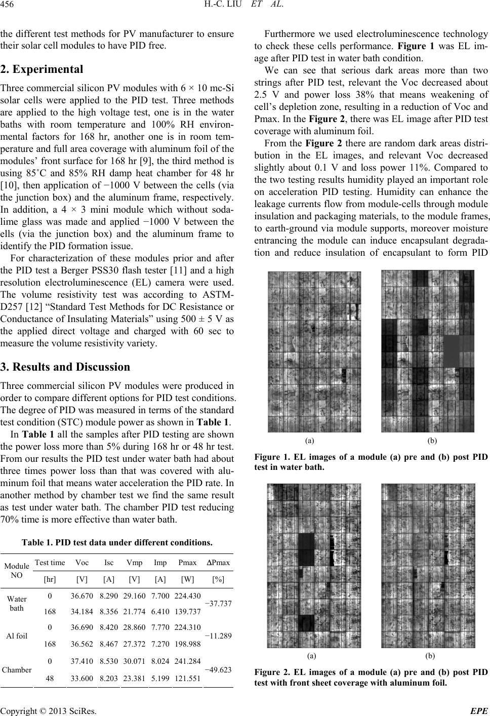 H.-C. LIU ET AL. 456 the different test methods for PV manufacturer to ensure their solar cell modules to have PID free. 2. Experimental Three commercial silicon PV modules with 6 × 10 mc-Si solar cells were applied to the PID test. Three methods are applied to the high voltage test, one is in the water baths with room temperature and 100% RH environ- mental factors for 168 hr, another one is in room tem- perature and full area coverage with aluminum foil of the modules’ front surface for 168 hr [9], the third method is using 85˚C and 85% RH damp heat chamber for 48 hr [10], then application of −1000 V between the cells (via the junction box) and the aluminum frame, respectively. In addition, a 4 × 3 mini module which without soda- lime glass was made and applied −1000 V between the ells (via the junction box) and the aluminum frame to identify the PID formation issue. For characterization of these modules prior and after the PID test a Berger PSS30 flash tester [11] and a high resolution electroluminescence (EL) camera were used. The volume resistivity test was according to ASTM- D257 [12] “Standard Test Methods for DC Resistance or Conductance of Insulating Materials” using 500 ± 5 V as the applied direct voltage and charged with 60 sec to measure the volume resistivity variety. 3. Results and Discussion Three commercial silicon PV modules were produced in order to compare different options for PID test conditions. The degree of PID was measured in terms of the standard test condition (STC) module power as shown in Table 1. In Table 1 all the samples after PID testing are shown the power loss more than 5% during 168 hr or 48 hr test. From our results the PID test under water bath had about three times power loss than that was covered with alu- minum foil that means water acceleration the PID rate. In another method by chamber test we find the same result as test under water bath. The chamber PID test reducing 70% time is more effective than water bath. Table 1. PID test data under different conditions. Test time Voc Isc Vmp Imp PmaxΔPmax Module NO [hr] [V] [A] [V] [A] [W] [%] 0 36.670 8.290 29.160 7.700 224.430 Water bath 168 34.184 8.356 21.774 6.410 139.737 −37.737 0 36.690 8.420 28.860 7.770 224.310 Al foil 168 36.562 8.467 27.372 7.270 198.988 −11.289 0 37.410 8.530 30.071 8.024 241.284 Chamber 48 33.600 8.203 23.381 5.199 121.551 −49.623 Furthermore we used electroluminescence technology to check these cells performance. Figure 1 was EL im- age after PID test in water bath condition. We can see that serious dark areas more than two strings after PID test, relevant the Voc decreased about 2.5 V and power loss 38% that means weakening of cell’s depletion zone, resulting in a reduction of Voc and Pmax. In the Figure 2, there was EL image after PID test coverage with aluminum foil. From the Figure 2 there are random dark areas distri- bution in the EL images, and relevant Voc decreased slightly about 0.1 V and loss power 11%. Compared to the two testing results humidity played an important role on acceleration PID testing. Humidity can enhance the leakage currents flow from module-cells through module insulation and packaging materials, to the module frames, to earth-ground via module supports, moreover moisture entrancing the module can induce encapsulant degrada- tion and reduce insulation of encapsulant to form PID (a) (b) Figure 1. EL images of a module (a) pre and (b) post PID test in water bath. (a) (b) Figure 2. EL images of a module (a) pre and (b) post PID test with front sheet coverage with aluminum foil. Copyright © 2013 SciRes. EPE 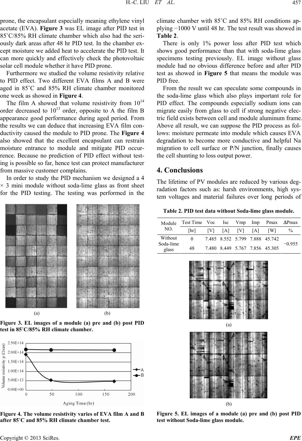 H.-C. LIU ET AL. 457 prone, the encapsulant especially meaning ethylene vinyl acetate (EVA). Figure 3 was EL image after PID test in 85˚C/85% RH climate chamber which also had the seri- ously dark areas after 48 hr PID test. In the chamber ex- cept moisture we added heat to accelerate the PID test. It can more quickly and effectively check the photovoltaic solar cell module whether it have PID prone. Furthermore we studied the volume resistivity relative to PID effect. Two different EVA films A and B were aged in 85˚C and 85% RH climate chamber monitored one week as showed in Figure 4. The film A showed that volume resistivity from 1014 order decreased to 1013 order, opposite to A the film B appearance good performance during aged period. From the results we can deduce that increasing EVA film con- ductivity caused the module to PID prone. The Figure 4 also showed that the excellent encapsulant can restrain moisture entrance to module and mitigate PID occur- rence. Because no prediction of PID effect without test- ing is possible so far, hence test can protect manufacturer from massive customer complains. In order to study the PID mechanism we designed a 4 × 3 mini module without soda-lime glass as front sheet for the PID testing. The testing was performed in the (a) (b) Figure 3. EL images of a module (a) pre and (b) post PID test in 85˚C/85% RH climate chamber. Figure 4. The volume resistivity varies of EVA film A and B after 85˚C and 85% RH climate chamber test. climate chamber with 85˚C and 85% RH conditions ap- plying −1000 V until 48 hr. The test result was showed in Table 2. There is only 1% power loss after PID test which shows good performance than that with soda-lime glass specimens testing previously. EL image without glass module had no obvious difference before and after PID test as showed in Figure 5 that means the module was PID free. From the result we can speculate some compounds in the soda-lime glass which also plays important role for PID effect. The compounds especially sodium ions can migrate easily from glass to cell if strong negative elec- tric field exists between cell and module aluminum frame. Above all result, we can suppose the PID process as fol- lows: moisture permeate into module which causes EVA degradation to become more conductive and helpful Na migration to cell surface or P/N junction, finally causes the cell shunting to loss output power. 4. Conclusions The lifetime of PV modules are reduced by various deg- radation factors such as: harsh environments, high sys- tem voltages and material failures over long periods of Table 2. PID test data without Soda-lime glass module. Test TimeVocIsc Vmp Imp PmaxΔPmax Module NO. [hr] [V][A] [V] [A] [W]% 0 7.4858.552 5.799 7.888 45.742 Without Soda-lime glass 48 7.4808.449 5.767 7.856 45.305 −0.955 (a) (b) Figure 5. EL images of a module (a) pre and (b) post PID test without Soda-lime glass module. Copyright © 2013 SciRes. EPE  H.-C. LIU ET AL. Copyright © 2013 SciRes. EPE 458 operation. In this article we investigated the high system voltage effect or PID effect. Our PID test results showed that PID in chamber is the harshest and fastest test method than in water bath and coverage with aluminum foil. Our results also verified that the volume resistivity and soda-lime glass ingredients are important factors to PID failure. Nowadays, PID effects are focused by every PV manufacturer to assure their products PID free. In the future how to reduce module PID effect to increase reli- ability and performance will lead PV modules to more competitiveness and wide acceptance of PV technolo- gies. 5. Acknowledgements The financial support provided by Bureau of Energy (contract No.: 102-D0305) is gratefully acknowledged. REFERENCES [1] R. Swanson, et al., “The Surface Polarization Effect in High-Efficiency Silicon Solar Cells,” Proceedings of the 15th International Photovoltaic Science & Engineering Conference, Shanghai, 11-13 October 2005, pp. 410-413. [2] J. A. del Cueto, “Degradation of Photovoltaic Modules under High Voltage Stress in the Field,” Proceedings of SPIE, Vol. 7773, 2010. [3] IEC 61215, “Crystalline Silicon Terrestrial Photovoltaic Modules—Design Qualification and Type Approval,” In- ternational Electrotechnical Commission, Geneva, 2005. [4] D. E. Carlson, et al., “Corrosion Effects in Thin-Film Photovoltaic Modules,” Progress in Photovoltaics: Re- search and Applications, Vol. 11, No. 6, 2003, pp. 377- 386. doi:10.1002/pip.500 [5] P. Hacke, et al., “Characterization of Multicrystalline Silicon Modules with System Bias Voltage Applied in Damp Heat,” Proceedings of the 25th European Photo- voltaic Solar Energy Conference and Exhibition, Valen- cia, 6-10 September 2010, pp. 3760-3765. [6] P. Hacke, et al., “System Voltage Potential-Induced Deg- radation Mechanisms in PV Modules and Methods for Test,” Proceedings of the 37th IEEE Photovoltaic Spe- cialists Conference, Seattle, 19-24 June 2011, pp. 000814- 000820. [7] M. Schütze, et al., “Investigations of Potential Induced Degradation of Silicon Photovoltaic Modules,” Proceed- ings of the 26th European Photovoltaic Solar Energy Conference and Exhibition, Hamburg, 5-8 September 2011, pp. 3097-3102 [8] H. C. Liu, C. T. Huang and W. K. Lee, “Study of Poten- tial Induced Degradation Mechanism in Commercial PV Module,” 38th IEEE PVSC, Austin, 2012, pp. 002442- 002444. [9] H. Nagel, A. Metz and K. Wangemann, “Crystalline Si Solar Cells And Modules Featuring Excellent Stability Against Potential-Induced Degradation,” Proceedings of the 26th European Photovoltaic Solar Energy Conference and Exhibition, Hamburg, 5-8 September 2011, pp. 3107- 3112. [10] S. Koch, et al., “Potential Induced Degradation Effects and Tests for Crystalline Silicon Cells,” Photovoltaic Module Reliability Workshop, Golden, 28 February-1 March 2012. [11] IEC 2007, “Photovoltaic Devices-Solar Simulator Per- formance Requirements,” IEC 60904-9 ed. 2, 2007. [12] ASTM-D257, “Standard Test Methods for DC Resistance or Conductance of Insulating Materials,” 2012. |