

Paper Menu >>
Journal Menu >>
 Circuits and Systems, 2011, 2, 14-17 doi:10.4236/cs.2011.21003 Published Online January 2011 (http://www.SciRP.org/journal/cs) Copyright © 2011 SciRes. CS A Novel Multifunction CFOA-Based Inverse Filter Hung-Yu Wang1, Sheng-Hsiung Chang2, Tzu-Yi Yang1, Po-Yang Tsai1 1Department of Electronic Engineering, National Kaohsiung University of Applied Scienc es, Ka o hsiu n g, Taiwan, China 2Department of Optoelectronic Engineering, Far East University, Hsin-Shih, Taiwan, China E-mail: [email protected] Received October 7, 2010; revised November 3, 2010; accepted November 17, 2010 Abstract We present a novel multifunction inverse biquad configuration based on current feedback operational ampli- fiers (CFOAs) and grounded passive elements. The proposed scheme can be used to realize inverse lowpass, inverse bandpass and inverse highpass filter functions. The relevant coefficients of the inverse filters are or- thogonal adjustable by independent passive elements. All the passive elements in the proposed scheme are grounded to benefit easier electronic tunability. With the high input impedance and low output impedance properties, the scheme is input and output cascadable for voltage operation. The feasibility of the proposed scheme is demonstrated by HSPICE simulations. Keywords: Multifunction, Inverse Filter, CFOA 1. Introduction In communication, control and instrumentation systems, there are numerous situations in which an electrical sig- nal is altered through a linear or nonlinear transformation by a processing or a transmission system. So it is neces- sary to recover the input signal from the available dis- torted output signal resulted from the signal progress. This can often be done by using a system that has an inverse transfer characteristic of the original system [1]. For digital signal processing, several methods for ob- taining digital inverse filters have been established [2]. Nevertheless, for analog signal processing, only a few works are known for realizing continuous-time analog inverse filters [1,3-6]. In [1], a general approach is presented for obtaining the inverse transfer function for linear dynamic systems and the inverse transfer characteristic for non-linear re- sistive circuits. In [3], a procedure for deriving cur- rent-mode, four-terminal floating nullor (FTFN)-based inverse filter from the voltage-mode filter is given. It uses the method in [1] and dual transformation [7] during the procedure. Due to the use of dual transformation, this approach can only be applied to planar circuit. By the use of adjoint transformation, another easier procedure for deriving current-mode FTFN-based inverse filter from the voltage-mode filter is presented and it is applicable to nonplanar circuits [4]. All the proposed approaches in [1,3,4] are useful for obtaining single-input single-output inverse filters. Additional various inverse current-mode and voltage-mode filters are presented in [5] and [6], respectively. However, each circuit proposed in [5,6] has one inverse filter function. In this paper, we present a novel inverse filter scheme based on CFOAs and grounded passive elements. By slight modification of the passive elements of the proposed scheme, various in- verse filter functions can be realized. The presented scheme possesses high input impedance and low output impedance which enables the convenience of connecting with the other stage in cascade. The workability of the proposed scheme is verified by HSPICE simulations. The simulated results confirm the theoretical prediction. 2. The Proposed Circuit The current-feedback operational amplifier, such as AD844 from Analog Devices Inc. [8], has gained the acceptance of researchers as a building block in circuit design. The advantages of CFOAs are their constant bandwidths, independent closed-loop gains and high slew-rate capabilities [9]. The CFOA can be described using the following matrix-relations: 0100 0000 1000 0010 xx yy zz ww VI I V I V VI . (1) 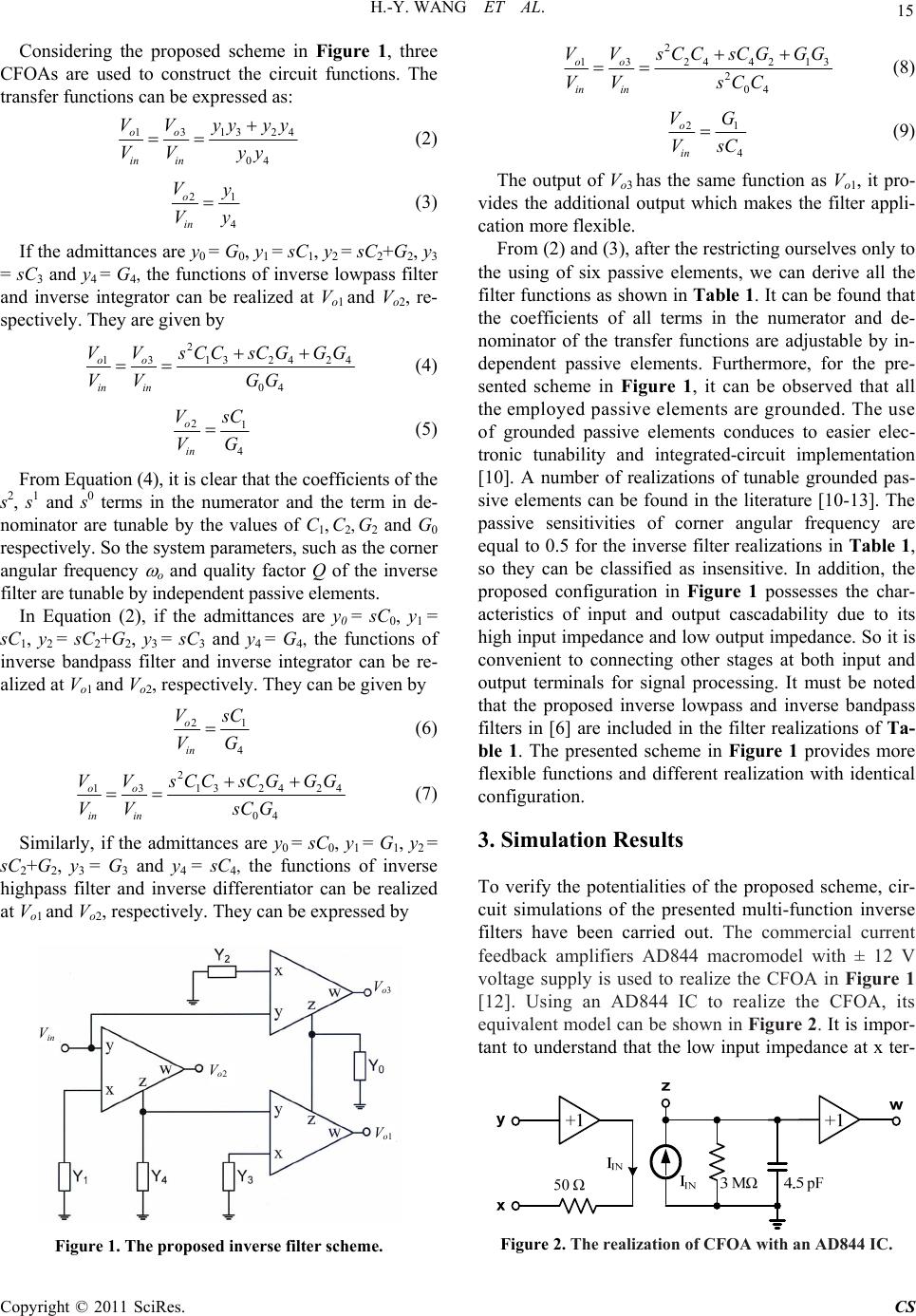 H.-Y. WANG ET AL. 15 Considering the proposed scheme in Figure 1, three CFOAs are used to construct the circuit functions. The transfer functions can be expressed as: 13132 04 oo in in VV yyyy VV yy 4 (2) 21 4 o in Vy Vy (3) If the admittances are y0 = G0, y1 = sC1, y2 = sC2+G2, y3 = sC3 and y4 = G4, the functions of inverse lowpass filter and inverse integrator can be realized at Vo1 and Vo2, re- spectively. They are given by 2 131324 24 04 oo in in VV sCCsCGGG VV GG (4) 21 4 o in V s C VG (5) From Equation (4), it is clear that the coefficients of the s2, s1 and s0 terms in the numerator and the term in de- nominator are tunable by the values of C1, C2, G2 and G0 respectively. So the system parameters, such as the corner angular frequency o and quality factor Q of the inverse filter are tunable by independent passive elements. In Equation (2), if the admittances are y0 = sC0, y1 = sC1, y2 = sC2+G2, y3 = sC3 and y4 = G4, the functions of inverse bandpass filter and inverse integrator can be re- alized at Vo1 and Vo2, respectively. They can be given by 21 4 o in V s C VG (6) 2 1 313 2424 04 oo in in VV sCCsCGGG VV sCG (7) Similarly, if the admittances are y0 = sC0, y1 = G1, y2 = sC2+G2, y 3 = G 3 and y4 = sC4, the functions of inverse highpass filter and inverse differentiator can be realized at Vo1 and Vo2, respectively. They can be expressed by Figure 1. The proposed inverse filter scheme. 2 13 24421 2 04 oo in in VV sCCsCGGG VV sCC 3 (8) 21 4 o in VG VsC (9) The output of Vo3 has the same function as Vo1, it pro- vides the additional output which makes the filter appli- cation more flexible. From (2) and (3), after the restricting ourselves only to the using of six passive elements, we can derive all the filter functions as shown in Tab le 1. It can be found that the coefficients of all terms in the numerator and de- nominator of the transfer functions are adjustable by in- dependent passive elements. Furthermore, for the pre- sented scheme in Figure 1, it can be observed that all the employed passive elements are grounded. The use of grounded passive elements conduces to easier elec- tronic tunability and integrated-circuit implementation [10]. A number of realizations of tunable grounded pas- sive elements can be found in the literature [10-13]. The passive sensitivities of corner angular frequency are equal to 0.5 for the inverse filter realizations in Tab le 1, so they can be classified as insensitive. In addition, the proposed configuration in Figure 1 possesses the char- acteristics of input and output cascadability due to its high input impedance and low output impedance. So it is convenient to connecting other stages at both input and output terminals for signal processing. It must be noted that the proposed inverse lowpass and inverse bandpass filters in [6] are included in the filter realizations of Ta - ble 1. The presented scheme in Figure 1 provides more flexible functions and different realization with identical configuration. 3. Simulation Results To verify the potentialities of the proposed scheme, cir- cuit simulations of the presented multi-function inverse filters have been carried out. The commercial current feedback amplifiers AD844 macromodel with ± 12 V voltage supply is used to realize the CFOA in Figure 1 [12]. Using an AD844 IC to realize the CFOA, its equivalent model can be shown in Figure 2. It is impor- tant to understand that the low input impedance at x ter- Vo3 Vin Vo2 Vo1 Figure 2. The realization of CFOA with an AD844 IC. Copyright © 2011 SciRes. CS 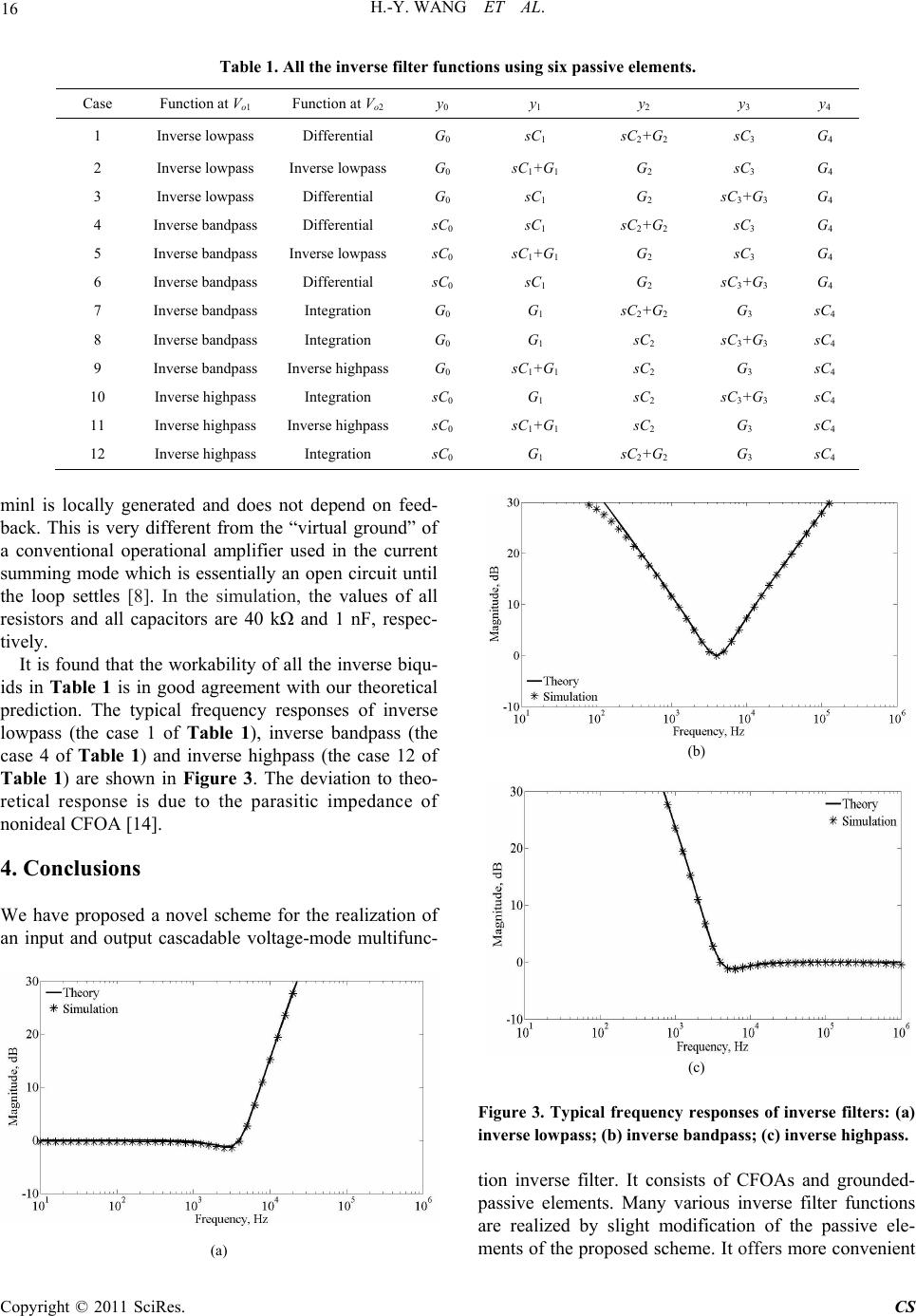 H.-Y. WANG ET AL. Copyright © 2011 SciRes. CS 16 Table 1. All the inverse filter functions using six passive elements. Case Function at Vo1 Function at Vo2 y0 y 1 y 2 y 3 y 4 1 Inverse lowpass Differential G0 sC1 sC2+G2 sC3 G 4 2 Inverse lowpass Inverse lowpass G0 sC1+G1 G 2 sC3 G 4 3 Inverse lowpass Differential G0 sC1 G 2 sC3+G3 G 4 4 Inverse bandpass Differential sC0 sC1 sC2+G2 sC3 G 4 5 Inverse bandpass Inverse lowpass sC0 sC1+G1 G 2 sC3 G 4 6 Inverse bandpass Differential sC0 sC1 G 2 sC3+G3 G 4 7 Inverse bandpass Integration G0 G 1 sC2+G2 G 3 sC4 8 Inverse bandpass Integration G0 G 1 sC2 sC3+G3 sC4 9 Inverse bandpass Inverse highpass G0 sC1+G1 sC2 G 3 sC4 10 Inverse highpass Integration sC0 G 1 sC2 sC3+G3 sC4 11 Inverse highpass Inverse highpass sC0 sC1+G1 sC2 G 3 sC4 12 Inverse highpass Integration sC0 G 1 sC2+G2 G 3 sC4 minl is locally generated and does not depend on feed- back. This is very different from the “virtual ground” of a conventional operational amplifier used in the current summing mode which is essentially an open circuit until the loop settles [8]. In the simulation, the values of all resistors and all capacitors are 40 kΩ and 1 nF, respec- tively. It is found that the workability of all the inverse biqu- ids in Table 1 is in good agreement with our theoretical prediction. The typical frequency responses of inverse lowpass (the case 1 of Table 1), inverse bandpass (the case 4 of Table 1) and inverse highpass (the case 12 of Table 1) are shown in Figure 3. The deviation to theo- retical response is due to the parasitic impedance of nonideal CFOA [14]. (b) 4. Conclusions We have proposed a novel scheme for the realization of an input and output cascadable voltage-mode multifunc- (c) Figure 3. Typical frequency responses of inverse filters: (a) inverse lowpass; (b) inverse bandpass; (c ) inver se highpass. tion inverse filter. It consists of CFOAs and grounded- passive elements. Many various inverse filter functions are realized by slight modification of the passive ele- ments of the proposed scheme. It offers more convenient (a)  H.-Y. WANG ET AL. 17 realizations for inverse filter functions. The feasibility of the proposed circuit is verified by simulation results. 5. References [1] A. Leuciuc, “Using Nullors for Realisation of Inverse Transfer Functions and Characteristics,” Electronics Let- ters, Vol. 33, No. 11, 1997, pp. 949-951. doi:10.1049 /el:19970637 [2] R. Kuc, “Introduction to Digital Signal Processing,” McGraw-Hill, New York, 1988. [3] B. Chipipop and W. Surakampontorn, “Realisation of Current-Mode FTFN-Based Inverse Filter,” Electronics Letters, Vol. 35, No. 9, 1999, pp. 690-692. doi:10.10 49/el:19990495 [4] H. Y. Wang and C. T. Lee, “Using Nullors for Realisa- tion of Current-Mode FTFN-Based Inverse Filters,” Electronic s Letters, Vol. 35, No. 22, 1999, pp. 1889-1890. doi:10.1049/el:19991336 [5] M. T. Abuelma’atti, “Identification of Cascadable Cur- rent-Mode Filters and Inverse-Filters Using Single FTFN,” Frequenz, Vol. 54, No. 11, 2000, pp. 284-289. [6] S. S. Gupta, D. R. Bhaskar, R. Senani and A. K. Singh, “Inverse Active Filters Employing CFOAs,” Electrical Engineering, Vol. 91, No. 1, 2009, pp. 23-26. doi:10.10 07/s00202-009-0112-3 [7] G. H. Wang, Y. Fukui, K. Kubota and K. Watanabe, “Voltage-Mode to Current-Mode Conversion by an Ex- tended Dual Transformation,” IEEE Proceedings Inter- national Symposium on Circuits and Systems, Singapore, 11-14 June 1991, pp. 1833-1836. [8] Analog Devices, 60 MHz 2000 V/μs Monolithic Op Amp AD844 Data sheet, Revision E, 2003. http://www. ana- log.com/static/imported-files/data_sheets/AD844.pdf [9] A. Fabre, “Insensitive Voltage-Mode and Current-Mode Filters from Commercially Available Transimpedance Opamps,” Circuits, Devices and Systems, IEE Proceed- ings G, Vol. 140, No. 5, 1993, pp. 319-321. doi:10.10 49/ip-g-2.1993.0053 [10] B. Nauta, “Analog CMOS Filters for Very High Fre- quencies,” Kluwer Academic Publishers, Norwell, 1993. [11] I. A. Khan and M. T. Ahmed, “OTA-Based Integrable Voltage/Current-Controlled Ideal C-Multiplier,” Elec- tronics Letters, Vol. 22, No. 7, 1986, pp. 365-366. doi:10. 1049/el:19860248 [12] K. Vavelidis and Y. Tsividis, “Design Considerations for a Highly Linear Electronically Tunable Resistor,” ISCA ’93, 1993 IEEE International Symposium on Circuits and Systems, Vol. 2, Chicago, 3-6 May 1993, pp. 1180-1183. [13] A. Worapishet and P. Khumsat, “Sub-Threshold R- MOSFET Tunable Resistor Technique,” Electronics Let- ters, Vol. 43, No. 7, 2007, pp. 390-392. doi:10.1049/el: 20070175 [14] J. A. Svoboda, L. McGory and S. Webb, “Applications of a Commercially Available Current Conveyor,” Interna- tional Journal of Electronics, Vol. 70, No. 1, 1991, pp. 159-164. doi:10.1080/00207219108921266 Copyright © 2011 SciRes. CS |