

Paper Menu >>
Journal Menu >>
 Smart Grid and Renewable Energy, 2013, 4, 409-418 http://dx.doi.org/10.4236/sgre.2013.45047 Published Online August 2013 (http://www.scirp.org/journal/sgre) Copyright © 2013 SciRes. SGRE 409 PV-Grid Tie System Energizing Water Pump Sameer Khader, Abdel-Karim Daud Electrical Engineering Department, Palestine Polytechnic University (PPU), Hebron, Palestine. Email: [email protected] Received June 27th, 2013; revised July 27th, 2013; accepted August 4th, 2013 Copyright © 2013 Sameer Khader, Abdel-Karim Daud. This is an open access article distributed under the Creative Commons At- tribution License, which permits unrestricted use, distribution, and reproduction in any medium, provided the original work is prop- erly cited. ABSTRACT This paper presents the behaviours of three-phase induction motor driving centrifugal pump under various solar irradia- tion levels, where the motor speed and torque depend on the source voltage and frequency, while the water-flow rate depends on the motor speed, density, and static head according to affinity flow. Matlab/Simulink model is proposed for studying the behaviours of these machines with respect to water flow capacity, motor current, electro-magnetic torque, and motor efficiency. The proposed photovoltaic with maximum power point tracking model based on observation and perturbation (O&P) maximum power tracking model is applied. The output voltage is regulated throughout Buck-Boost converter with purpose maintaining the output voltage at predetermined values. Since Induction motors are widely used in pump systems, the electromagnetic torque, water-flow rate are studied for various source frequencies. Comparison analysis is conducted for both motors with respect to water flow-rate, heads elevation, and motor current. In addition to that, the proposed system presents Photovoltaic-Grid (PV-Grid) Integrated model, where the power shortage required for normally operation of the pump is drawn from the electrical grid. Keywords: Photovoltaic; Induction Motor; Centrifugal Pumps; Electrical Grids; Matlab/Simulink 1. Introduction Photovoltaic energy resources presents alternative and friendly to the environment sources. It presents unique solution for providing remote area with clean and sus- tainable energy during the daytime in heating, lighting, refrigeration and water pumps systems [1-3] without the need of battery system, while during the night time the accumulated energy can be fully or partially used to cover the energy domain. The output circuit connected to the photovoltaic system is usually dc-dc converters main- ly boost choppers in order to boost the voltage to the predetermined levels. The DC/DC converters are widely used in regulated switch mode power supplies, where the input voltage to these converters varies in wide range especially in the case of Photovoltaic (PV) supply source due to unpre- dictable and sudden change in the solar irradiation level as well as the cell operating temperature. Several con- nection topologies concerning the switching systems have been proposed [4-8] aiming at realizing the required voltage level during different periods of day for certain applications such as pumps, motors in general and power supplies. On the other hand water flow consumption determines the rate of motor speed according to affinity law [6,7] which in turn determines the elevation (static head) and consumed power. Variable Frequency Drive (VFD) can be applied to achieve up mentioned facts. The proposed model consists of several modules as shown in Figure 1 with the following functions: PV Photovoltaic Array (PV) that converts the solar irradiation into voltage Vpv and current Ipv. Buck-Boost DC Chopper Module that boosts up the PV voltage to the predetermined levels. Conversely in case of high Vpv the output voltage is reduced. MPPT, maximum power point tracking unit that tracks the optimized operation point for power extrac- tion by controlling the chopper duty cycle. Variable Frequency Drive that controls the speed and torque of three-phase induction motor driving centrifugal pump by controlling the voltage and fre- quency. Speed-Flow Control Unit that determines the requir- ed voltage and frequency aiming at regulating the motor speed and torque according to actual water flow consumption.  PV-Grid Tie System Energizing Water Pump Copyright © 2013 SciRes. SGRE 410 PV Array Buck-Boost Chopper Power Estimator AC-DC Converter PV-Grid Integrator Va ri abl e Frequency Drive 3-phase IM Speed-Flow Control Unit Pump MPPT AC Grid P G P PV Q act P L Q ref P mech P in p Figure 1. Functional block diagram of proposed model. Power Estimator that detects the available Ppv power, the consumed motor power PL and the amount of power shortage PG that should be supplied from AC- grid. PV-Grid Integrator that provides the load with nec- essary power taken from either one of the sources PV or AC grid, or from both. Amount of power shortage PG that should be supplied from AC-grid. AC-DC Converter that converts the grid voltage into smoothed DC voltage that should be easily tied to the PV output terminal aiming at avoiding synchronizing procedures. The proposed model differs from other models, where the system is consumed energy from the grid in case of energy shortages and night time operation. It is fully simulated using Matlab/Simulink, where the system pa- rameters can be changed and investigated. 2. Modeling of Proposed Electrical Model 2.1. PV Performances The application of Photovoltaic solar energy in energiz- ing electrical load on-grid connected, where the pump power is controlled based on the extracted from the PV module power. 2.1.1. Phot ov o l tai c Mo del In terpretation Basically, PV cell is a P-N semiconductor junction that directly converts light energy into electricity. It has the equivalent circuit shown in Figure 2 [9,10]. The following are the simplified equations describing Figure 2. Equivalent circuit for PV cell. the cell output voltage and current: ln ph do c oso o III AKT VRI qI (1) e1 os c qV N AKT op phd INI I (2) 311 e g rc qE B KT T c dor r T II T (3) ; t p hpscncr nr I NI ITTGG (4) The idealistic diode idealistic factors A & B are with values vary between 1 and 2 depending on I-V perform- ance shaping and approximations. 2.1.2. Photovoltaic I-V Performance In order to study the I-V performance of the PV circuit and to look for appropriate dc chopper for boosting up the output voltage to predetermined value it is necessary to illustrate the obtained PV voltage and current for boost chopper according to specifications given in Table 1 at  PV-Grid Tie System Energizing Water Pump Copyright © 2013 SciRes. SGRE 411 reference irradiation (Gr = 1000 W/m2). The PV Array voltage can be obtained by multiplying the module volt- age and current by Nsm and Npm. Figure 3 illustrates the proposed PV array built in Matlab/Simulink [11] with R-L load, where the obtained results for different varia- tion levels are presented. From these performances it is shown that the total output PV voltage and current varies according to irradiation level with approximated 65 W maximum power at G = 1000 W/m2. Table 1. Data specification for PV Array. q K Iph I d R S R P 1.602e - 19 C1.38e - 23J/˚K4 A 0.2 mA 1 m10 k NS N P V O V OC I SC V MPP 38 4 0.6 V 21.5 V 4 A 17.5 V IMPP N Sm N Pm V pv R load T C 3.7 A 6 1 130 V 44 25˚C powergui C ontinuous V2 v + - V1 v + - T_ var 11.2903 T 1 Rf- Cf R-L PV Array T G Ns Np GND +V pv Output Nsm 6 Npm 1 Lo I i +- G_var2 G_T (a) 05 10 15 20 25 0 0.5 1 1.5 2 2.5 3 3.5 4 4.5 5 Ipv,A I-V performance Vpv, V 1200W/m2 1000W/m2 800W/m2 600W/m2 400W/m2 (b) Figure 3. PV model with I-V performances. (a) Proposed model for PV array in Simulink environment; (b) I-V performance of PV module.  PV-Grid Tie System Energizing Water Pump Copyright © 2013 SciRes. SGRE 412 2.2. The Integration of PV with Water Pumping System A centrifugal pumps are used as electrical load [6], where the pump power, speed and torque are directly affected by either load-side parameters in form of water flow-rate, static head, water pressure, and line side in form of solar irradiation, weather conditions, and ex- tracted power. Figure 4 illustrates PV solar system ener- gized water pump installation, where the water pumping system can be directly energized from the PV or indi- rectly throughout battery bank [10]. Both configurations have their advantages and disadvantages. Direct-coupled pumping systems illustrated in Figure 4(a) are sized to store extra water on sunny days so it is available on cloudy days and at night. Water can be stor- ed in a larger-than-needed watering tank or in a separate storage tank and then gravity-fed to smaller watering tanks. Water-storage capacity is important in this pump- ing system. While Figure 4(b) illustrates battery-coupled water pumping systems which consist of photovoltaic (PV) panels, charge control regulator, batteries, pump control- ler, pressure switch, tank, and AC water pump. The elec- tric current produced by PV panels during daylight hours charges the batteries, and the batteries in turn supply power to the pump anytime water is needed. The use of batteries spreads the pumping over a longer period of time by providing a variable voltage and frequency de- pending on the water-consumption rate, which in turn reduces the pump losses and increases the battery dis- charging time which is an important factor during the night and low light periods, the system can still deliver a needed rate of water for livestock. 2.2.1. Centrifugal Pump Performances According to [8] the power demand of the water pump is expressed using the following expression: p p g QH P (5) The pump operational performance which presents the relationships between total head including static head and friction head, water flow-rate, and pump efficiency are illustrated in Figure 5 for certain commercial pump. By applying the principle of motor-pump power bal- ance, Equation (5) can be integrated with motor speed- torque performance as: pm gQH T (6) Now referring to Figure 5 where the pump (H-Q) curve is illustrated, which normally used to locate the pump’s operation point. For exact determining the men- tioned operation point there is a need to determine the total head of the installation HA, which is the sum of the (a) (b) Figure 4. PV system energizing water-pumping systems. (a) Direct-coupled water-pumping systems; (b) Battery-cou- pled water-pumping systems. Figure 5. Water pump operational characteristic. static head HS known as elevation difference, and the network hydraulic losses HL, thus : 2 AsL H HH hQ (7) The friction coefficient depends on the system in- stallation, pipes section, and liquid viscosity. The opera- tion point results by the application of the following equation: A H H (8) This condition can be obtained by intersecting of the corresponding curves of Figure 5. 2.2.2. Electrical Motor Performances Centrifugal pumps can be driven by either direct current motors [9] or alternating current motors, mainly induc- 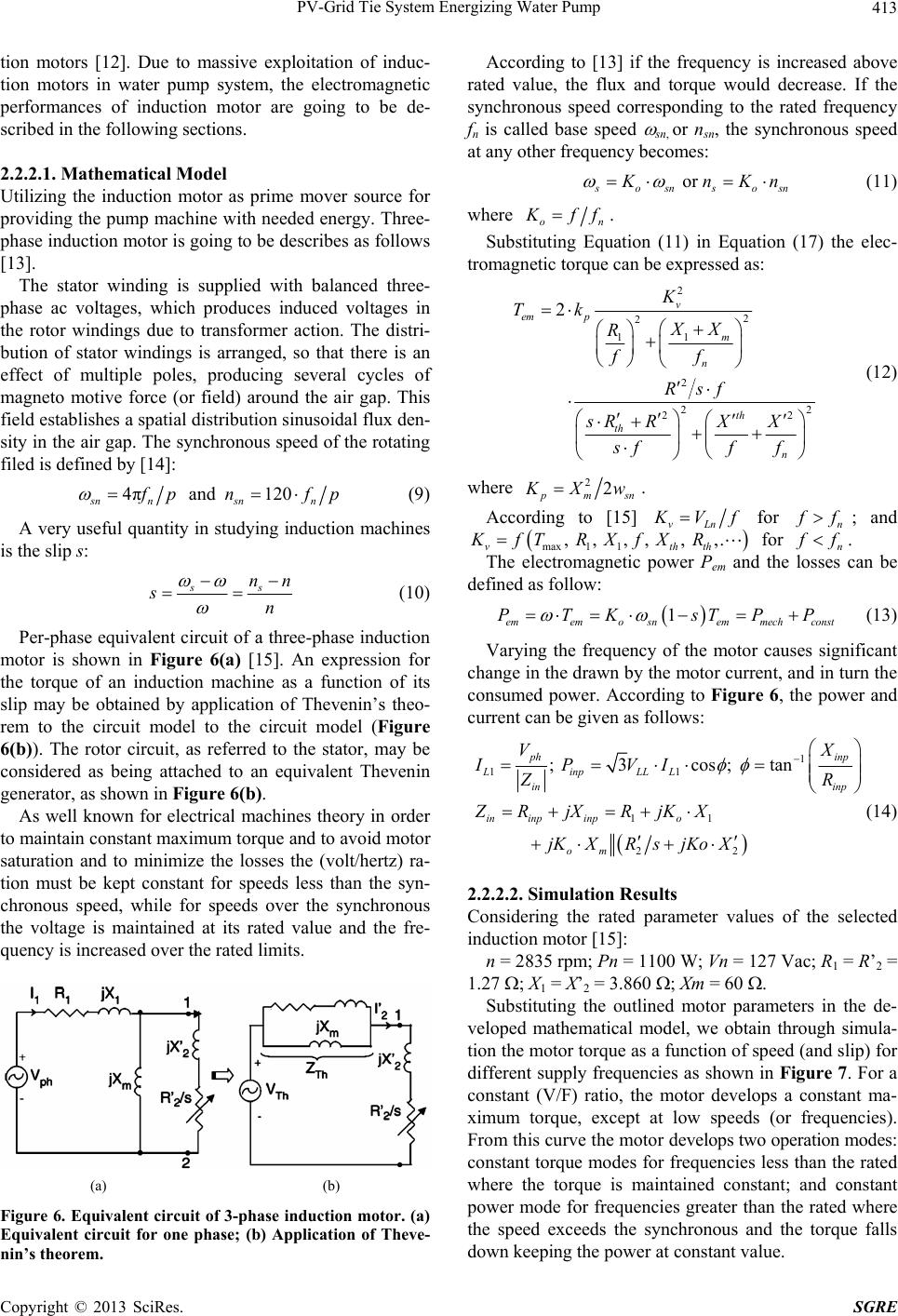 PV-Grid Tie System Energizing Water Pump Copyright © 2013 SciRes. SGRE 413 tion motors [12]. Due to massive exploitation of induc- tion motors in water pump system, the electromagnetic performances of induction motor are going to be de- scribed in the following sections. 2.2.2.1. M at h ematical Model Utilizing the induction motor as prime mover source for providing the pump machine with needed energy. Three- phase induction motor is going to be describes as follows [13]. The stator winding is supplied with balanced three- phase ac voltages, which produces induced voltages in the rotor windings due to transformer action. The distri- bution of stator windings is arranged, so that there is an effect of multiple poles, producing several cycles of magneto motive force (or field) around the air gap. This field establishes a spatial distribution sinusoidal flux den- sity in the air gap. The synchronous speed of the rotating filed is defined by [14]: 4π and 120 sn nsnn f pn fp (9) A very useful quantity in studying induction machines is the slip s: ss nn sn (10) Per-phase equivalent circuit of a three-phase induction motor is shown in Figure 6(a) [15]. An expression for the torque of an induction machine as a function of its slip may be obtained by application of Thevenin’s theo- rem to the circuit model to the circuit model (Figure 6(b)). The rotor circuit, as referred to the stator, may be considered as being attached to an equivalent Thevenin generator, as shown in Figure 6(b). As well known for electrical machines theory in order to maintain constant maximum torque and to avoid motor saturation and to minimize the losses the (volt/hertz) ra- tion must be kept constant for speeds less than the syn- chronous speed, while for speeds over the synchronous the voltage is maintained at its rated value and the fre- quency is increased over the rated limits. (a) (b) Figure 6. Equivalent circuit of 3-phase inducti on motor. (a) Equivalent circuit for one phase; (b) Application of Theve- nin’s theorem. According to [13] if the frequency is increased above rated value, the flux and torque would decrease. If the synchronous speed corresponding to the rated frequency fn is called base speed sn, or nsn, the synchronous speed at any other frequency becomes: or s osnsosn K nKn (11) where on K ff . Substituting Equation (11) in Equation (17) the elec- tromagnetic torque can be expressed as: 2 2 2 1 1 2 22 22 2 v em p m n th th n K Tk XX R ff Rsf sR RXX sff f (12) where 22 pmsn K Xw. According to [15] vLn K Vf for n f f; and max 11 , , , , , ,. vthth KfTRXfXR for n f f . The electromagnetic power Pem and the losses can be defined as follow: 1 ememo snemmechconst PTK sTPP (13) Varying the frequency of the motor causes significant change in the drawn by the motor current, and in turn the consumed power. According to Figure 6, the power and current can be given as follows: 1 11 11 22 ; 3 cos; tan ph inp LinpLLL in inp in inpinpo om VX IPVI ZR ZR jXRjKX jKXRsjKo X (14) 2.2.2.2. Simulation Resul ts Considering the rated parameter values of the selected induction motor [15]: n = 2835 rpm; Pn = 1100 W; Vn = 127 Vac; R1 = R’2 = 1.27 ; X1 = X’2 = 3.860 ; Xm = 60 . Substituting the outlined motor parameters in the de- veloped mathematical model, we obtain through simula- tion the motor torque as a function of speed (and slip) for different supply frequencies as shown in Figure 7. For a constant (V/F) ratio, the motor develops a constant ma- ximum torque, except at low speeds (or frequencies). From this curve the motor develops two operation modes: constant torque modes for frequencies less than the rated where the torque is maintained constant; and constant power mode for frequencies greater than the rated where the speed exceeds the synchronous and the torque falls down keeping the power at constant value. 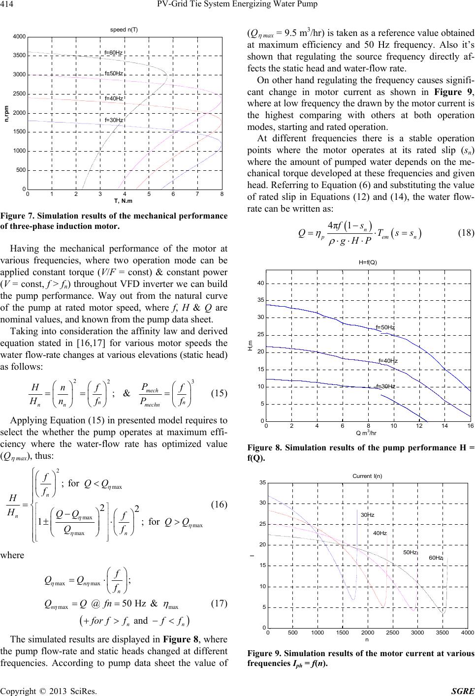 PV-Grid Tie System Energizing Water Pump Copyright © 2013 SciRes. SGRE 414 0 1 2 345 6 78 0 500 1000 1500 2000 2500 3000 3500 4000 s peed n(T) T, N.m n,rpm f=30Hz f=40Hz f=50Hz f=60Hz Figure 7. Simulation results of the mechanical performance of three-phase induction motor. Having the mechanical performance of the motor at various frequencies, where two operation mode can be applied constant torque (V/F = const) & constant power (V = const, f > fn) throughout VFD inverter we can build the pump performance. Way out from the natural curve of the pump at rated motor speed, where f, H & Q are nominal values, and known from the pump data sheet. Taking into consideration the affinity law and derived equation stated in [16,17] for various motor speeds the water flow-rate changes at various elevations (static head) as follows: 223 ; & mech nn n nmechn P H nf f H nfP f (15) Applying Equation (15) in presented model requires to select the whether the pump operates at maximum effi- ciency where the water-flow rate has optimized value (Q max), thus: 2 max max max max ; for 22 1;for n n n fQQ f H HQQ fQQ Qf (16) where max max max max ; @ 50 Hz & and n n n nn f QQ f QQfn f or ffff (17) The simulated results are displayed in Figure 8, where the pump flow-rate and static heads changed at different frequencies. According to pump data sheet the value of (Q max = 9.5 m3/hr) is taken as a reference value obtained at maximum efficiency and 50 Hz frequency. Also it’s shown that regulating the source frequency directly af- fects the static head and water-flow rate. On other hand regulating the frequency causes signifi- cant change in motor current as shown in Figure 9, where at low frequency the drawn by the motor current is the highest comparing with others at both operation modes, starting and rated operation. At different frequencies there is a stable operation points where the motor operates at its rated slip (sn) where the amount of pumped water depends on the me- chanical torque developed at these frequencies and given head. Referring to Equation (6) and substituting the value of rated slip in Equations (12) and (14), the water flow- rate can be written as: 4π1n p em n fs QTss gHP (18) 0 24 6810 12 1416 0 5 10 15 20 25 30 35 40 H=f(Q) Q m3/hr H,m f=50Hz f=40Hz f=30Hz Q m 3 /h r Figure 8. Simulation results of the pump performance H = f(Q). 05001000 1500 2000 2500 3000 3500 4000 0 5 10 15 20 25 30 35 Curren t I(n ) n I 30Hz 40Hz 50Hz60Hz Figure 9. Simulation results of the motor current at various frequencies Iph = f(n). 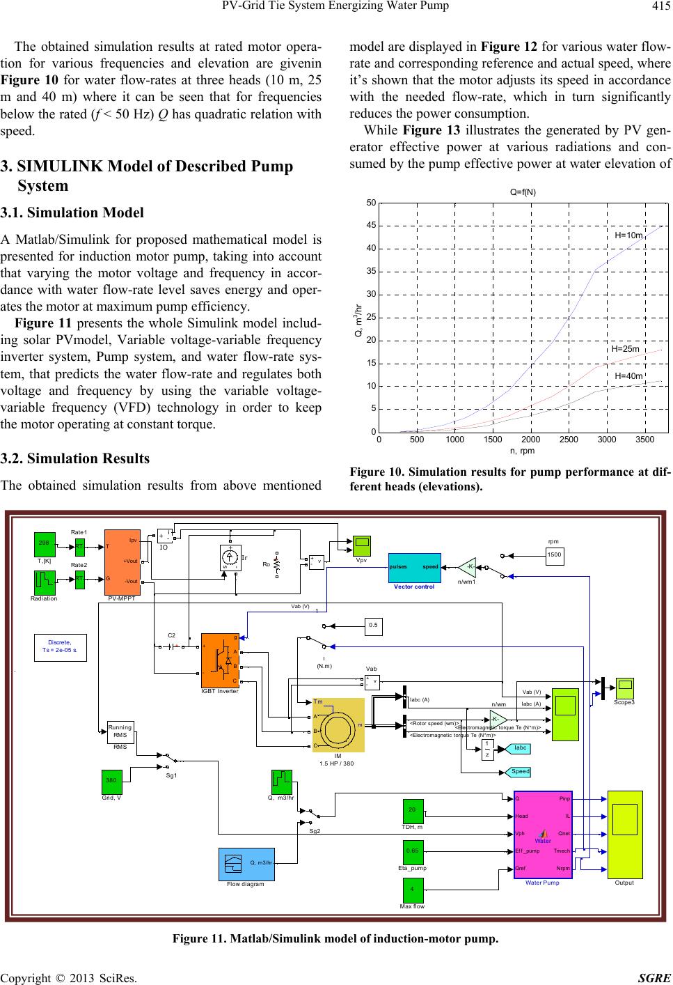 PV-Grid Tie System Energizing Water Pump Copyright © 2013 SciRes. SGRE 415 The obtained simulation results at rated motor opera- tion for various frequencies and elevation are givenin Figure 10 for water flow-rates at three heads (10 m, 25 m and 40 m) where it can be seen that for frequencies below the rated (f < 50 Hz) Q has quadratic relation with speed. 3. SIMULINK Model of Described Pump System 3.1. Simulation Model A Matlab/Simulink for proposed mathematical model is presented for induction motor pump, taking into account that varying the motor voltage and frequency in accor- dance with water flow-rate level saves energy and oper- ates the motor at maximum pump efficiency. Figure 11 presents the whole Simulink model includ- ing solar PVmodel, Variable voltage-variable frequency inverter system, Pump system, and water flow-rate sys- tem, that predicts the water flow-rate and regulates both voltage and frequency by using the variable voltage- variable frequency (VFD) technology in order to keep the motor operating at constant torque. 3.2. Simulation Results The obtained simulation results from above mentioned model are displayed in Figure 12 for various water flow- rate and corresponding reference and actual speed, where it’s shown that the motor adjusts its speed in accordance with the needed flow-rate, which in turn significantly reduces the power consumption. While Figure 13 illustrates the generated by PV gen- erator effective power at various radiations and con- sumed by the pump effective power at water elevation of 05001000 1500 2000 2500 3000 3500 0 5 10 15 20 25 30 35 40 45 50 Q= f(N) n, rpm Q, m3/hr H=10m H=25m H=40m Q, m 3 /hr Figure 10. Simulation results for pump performance at dif- ferent heads (elevations). T (N. m) 1500 rpm Discrete, Ts = 2e-05 s. -K - n/wm1 -K - n/wm Q Head Vph Eff_pump Qref Pinp IL Qnet Tmech Nrpm Water Water Pump Vpv v + -speedpulses Vector control v + - Vab z 1 20 TDH, m 298 T,[K] Sg2 Sg1 Scope3 + Ro RT Ra te2 RT Ra te1 Radiation Running RMS RMS Q, m3/hr T G Ipv +Vout -Vout PV-MPPT Outpu t 4 Max flow s -+ Ir i +- IO m A B C Tm IM 1.5 HP / 380 g A B C + - IGBT In verter 380 Grid, V Iabc Speed Q, m3/hr Flow diagram 0.65 Eta_pump 0.5 + C2 1 <Rot or s peed (wm)> Iabc (A) Iabc (A) Vab (V) Vab (V) <Elect rom agnet ic t orque Te (N* m )> <Elect rom agnet ic t orque Te (N* m )> Figure 11. Matlab/Simulink model of induction-motor pump. 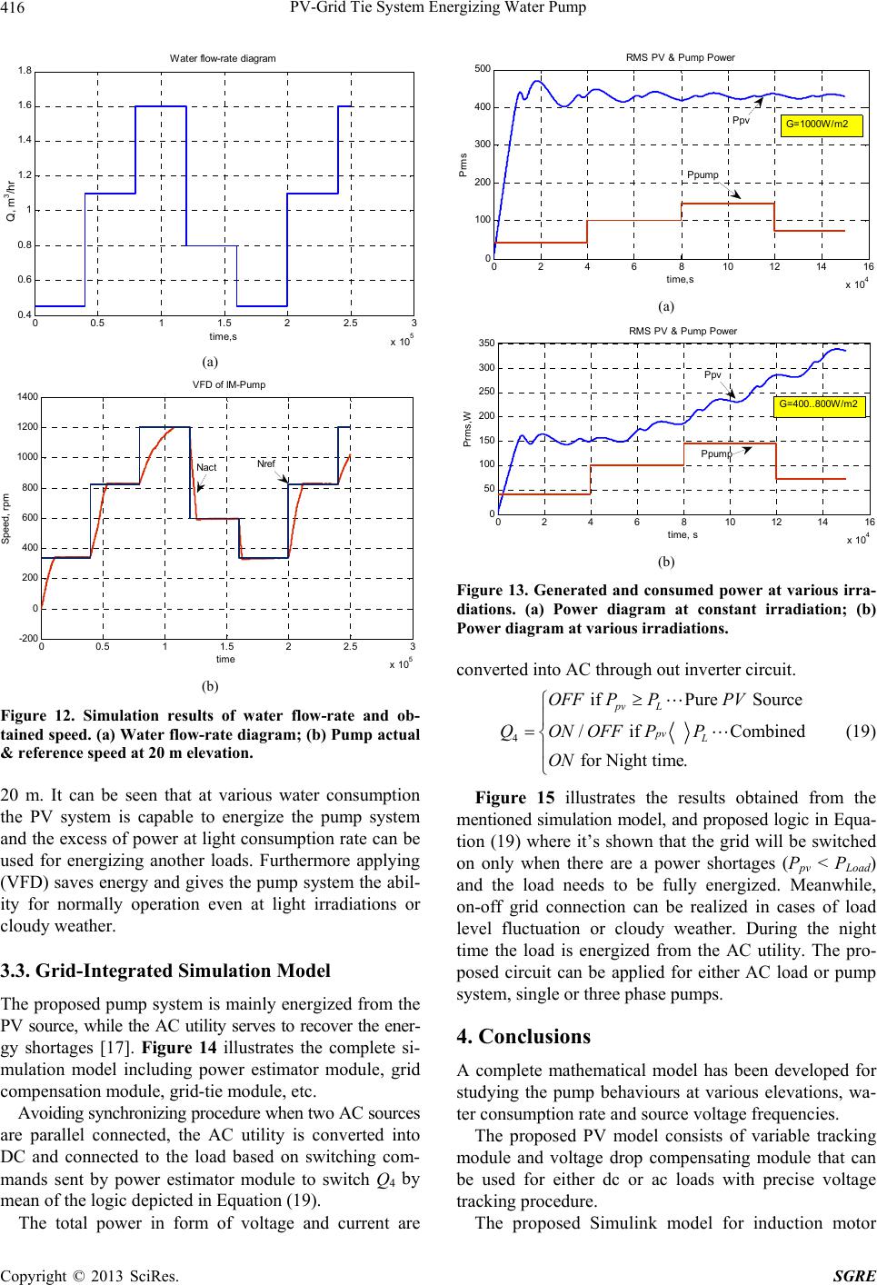 PV-Grid Tie System Energizing Water Pump Copyright © 2013 SciRes. SGRE 416 00.5 11.5 22.5 3 x 10 5 0.4 0.6 0.8 1 1.2 1.4 1.6 1.8 time,s Q, m3/hr Water flow-rate di agram Q, m 3 /hr (a) 00.5 11.5 22.5 3 x 10 5 -200 0 200 400 600 800 1000 1200 1400 time Speed, rpm VF D of IM-Pum p Nref Nact (b) Figure 12. Simulation results of water flow-rate and ob- tained speed. (a) Water flow-rate diagram; (b) Pump actual & reference speed at 20 m elevation. 20 m. It can be seen that at various water consumption the PV system is capable to energize the pump system and the excess of power at light consumption rate can be used for energizing another loads. Furthermore applying (VFD) saves energy and gives the pump system the abil- ity for normally operation even at light irradiations or cloudy weather. 3.3. Grid-Integrated Simulation Model The proposed pump system is mainly energized from the PV source, while the AC utility serves to recover the ener- gy shortages [17]. Figure 14 illustrates the complete si- mulation model including power estimator module, grid compensation module, grid-tie module, etc. Avoiding synchronizing procedure when two AC sources are parallel connected, the AC utility is converted into DC and connected to the load based on switching com- mands sent by power estimator module to switch Q4 by mean of the logic depicted in Equation (19). The total power in form of voltage and current are 0246810 12 1416 x 10 4 0 100 200 300 400 500 time,s Prms RMS PV & Pump Power Ppump PpvG=1000W/m2 (a) 0 2 4 6810 12 14 16 x 10 4 0 50 100 150 200 250 300 350 time, s Prms,W RMS PV & Pump Power Ppv G= 400..800W/m 2 Ppump (b) Figure 13. Generated and consumed power at various irra- diations. (a) Power diagram at constant irradiation; (b) Power diagram at various irradiations. converted into AC through out inverter circuit. 4 if Pure Source / if Combined for Night time. pv L pv L OFF PPPV QONOFFPP ON (19) Figure 15 illustrates the results obtained from the mentioned simulation model, and proposed logic in Equa- tion (19) where it’s shown that the grid will be switched on only when there are a power shortages (Ppv < PLoad) and the load needs to be fully energized. Meanwhile, on-off grid connection can be realized in cases of load level fluctuation or cloudy weather. During the night time the load is energized from the AC utility. The pro- posed circuit can be applied for either AC load or pump system, single or three phase pumps. 4. Conclusions A complete mathematical model has been developed for studying the pump behaviours at various elevations, wa- ter consumption rate and source voltage frequencies. The proposed PV model consists of variable tracking module and voltage drop compensating module that can be used for either dc or ac loads with precise voltage tracking procedure. The proposed Simulink model for induction motor 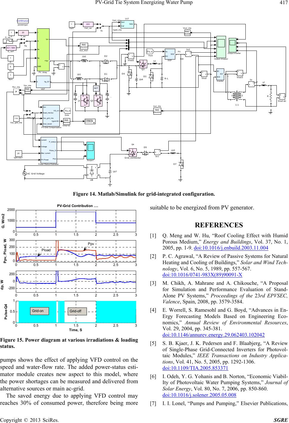 PV-Grid Tie System Energizing Water Pump Copyright © 2013 SciRes. SGRE 417 Ipv Vact_rms V grid_rms Q4 Grid PV Continuous powergui RMS ( discrete) Vrms+dv 220 Vref_var 1 Vref1 RMS d iscrete Vpv_rms RMS d iscrete Vout_ rms v + - Vout3 v + - Vout2 v + - Vout-ac v + - Vout 110 Vac_grid_rms Vact Vref Gate VVT GVg_Q1 VGT 110.1 A B + - UB 20 T_var 1 T Sv Sg Scope1 R-L R g CE Q3 g C E Q2 g C E Q1 Ppv_rms current Voltage Max current PV-Power P_status Pulse_G Ptot Power Status Estimater T G Ns Np Ipv GND +Vpv PV Array Output chopper Vg DCi DCO OCP 6 Ns 1 Npm Ls Lf Lb7 Lb4 Lb3 Lb2 Lb1 Irms_load RMS (discrete) Iout_rms1 RMS (discrete) Iout_rms i +- Io2 i +- Io1 i +- Io DC AC2 AC1 Inverter 20 Igrid-max1 g CE Grid_co nnector [Vg_p] Goto 821.1984 G_var1 G_var 1 G [Vg_p] From D7 D5 D4 D3 D2 D1 AC Grid Voltage 12 1:1 .- Vpv Iload_r ms/Ipv Vac_grid_rms Vout_boost VG_ch Vgrid+DV PV-Grid Compensation Output inverter v + - NOT Figure 14. Matlab/Simulink for grid-integrated configuration. 00.5 11.5 22.5 3 0 1000 2000 G, W/ m2 00.5 11.5 22.5 3 0 100 200 300 Ppv, Pload, W 00.5 11.5 22.5 3 -200 0 200 dp, W 00.5 11.5 22.5 3 0 0. 5 1 Pulse-Q4 Tim e, S PV-Grid Contribution .. . . Grid-off Grid-on Ppv Pload Figure 15. Power diagram at various irradiations & loading status. pumps shows the effect of applying VFD control on the speed and water-flow rate. The added power-status esti- mator module creates new aspect to this model, where the power shortages can be measured and delivered from alternative sources or main ac-grid. The saved energy due to applying VFD control may reaches 30% of consumed power, therefore being more suitable to be energized from PV generator. REFERENCES [1] Q. Meng and W. Hu, “Roof Cooling Effect with Humid Porous Medium,” Energy and Buildings, Vol. 37, No. 1, 2005, pp. 1-9. doi:10.1016/j.enbuild.2003.11.004 [2] P. C. Agrawal, “A Review of Passive Systems for Natural Heating and Cooling of Buildings,” Solar and Wind Tech- nology, Vol. 6, No. 5, 1989, pp. 557-567. doi:10.1016/0741-983X(89)90091-X [3] M. Chikh, A. Mahrane and A. Chikouche, “A Proposal for Simulation and Performance Evaluation of Stand- Alone PV Systems,” Proceedings of the 23rd EPVSEC, Valence, Spain, 2008, pp. 3579-3584. [4] E. Worrell, S. Ramesohl and G. Boyd, “Advances in En- Ergy Forecasting Models Based on Engineering Eco- nomics,” Annual Review of Environmental Resources, Vol. 29, 2004, pp. 345-381. doi:10.1146/annurev.energy.29.062403.102042 [5] S. B. Kjaer, J. K. Pedersen and F. Blaabjerg, “A Review of Single-Phase Grid-Connected Inverters for Photovol- taic Modules,” IEEE Transactions on Industry Applica- tions, Vol. 41, No. 5, 2005, pp. 1292-1306. doi:10.1109/TIA.2005.853371 [6] I. Odeh, Y. G. Yohanis and B. Norton, “Economic Viabil- Ity of Photovoltaic Water Pumping Systems,” Journal of Solar Energy, Vol. 80, No. 7, 2006, pp. 850-860. doi:10.1016/j.solener.2005.05.008 [7] I. I. Lonel, “Pumps and Pumping,” Elsevier Publications, 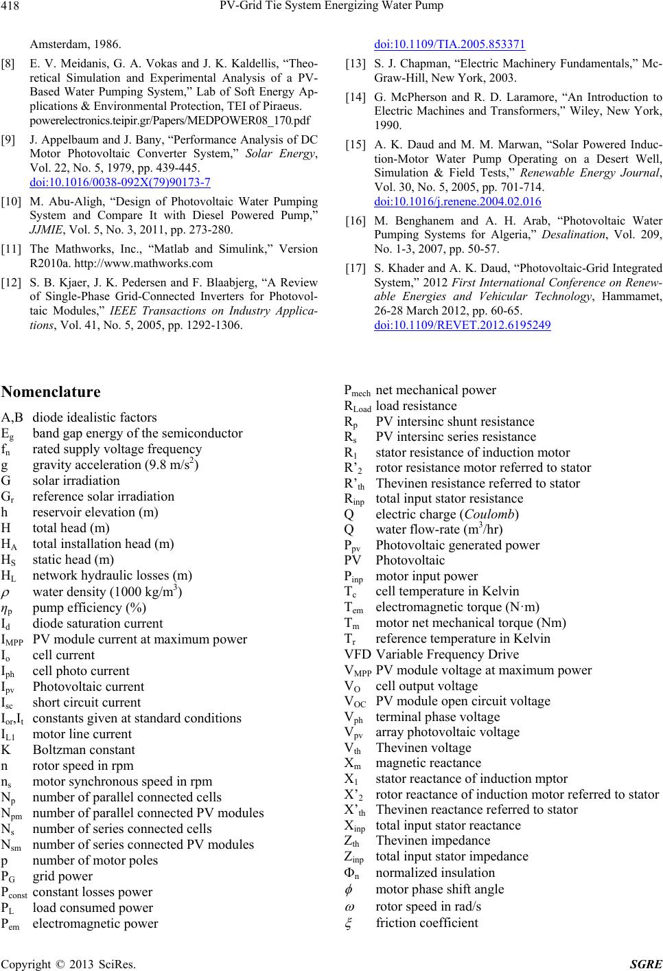 PV-Grid Tie System Energizing Water Pump Copyright © 2013 SciRes. SGRE 418 Amsterdam, 1986. [8] E. V. Meidanis, G. A. Vokas and J. K. Kaldellis, “Theo- retical Simulation and Experimental Analysis of a PV- Based Water Pumping System,” Lab of Soft Energy Ap- plications & Environmental Protection, TEI of Piraeus. powerelectronics.teipir.gr/Papers/MEDPOWER08_170.pdf [9] J. Appelbaum and J. Bany, “Performance Analysis of DC Motor Photovoltaic Converter System,” Solar Energy, Vol. 22, No. 5, 1979, pp. 439-445. doi:10.1016/0038-092X(79)90173-7 [10] M. Abu-Aligh, “Design of Photovoltaic Water Pumping System and Compare It with Diesel Powered Pump,” JJMIE, Vol. 5, No. 3, 2011, pp. 273-280. [11] The Mathworks, Inc., “Matlab and Simulink,” Version R2010a. http://www.mathworks.com [12] S. B. Kjaer, J. K. Pedersen and F. Blaabjerg, “A Review of Single-Phase Grid-Connected Inverters for Photovol- taic Modules,” IEEE Transactions on Industry Applica- tions, Vol. 41, No. 5, 2005, pp. 1292-1306. doi:10.1109/TIA.2005.853371 [13] S. J. Chapman, “Electric Machinery Fundamentals,” Mc- Graw-Hill, New York, 2003. [14] G. McPherson and R. D. Laramore, “An Introduction to Electric Machines and Transformers,” Wiley, New York, 1990. [15] A. K. Daud and M. M. Marwan, “Solar Powered Induc- tion-Motor Water Pump Operating on a Desert Well, Simulation & Field Tests,” Renewable Energy Journal, Vol. 30, No. 5, 2005, pp. 701-714. doi:10.1016/j.renene.2004.02.016 [16] M. Benghanem and A. H. Arab, “Photovoltaic Water Pumping Systems for Algeria,” Desalination, Vol. 209, No. 1-3, 2007, pp. 50-57. [17] S. Khader and A. K. Daud, “Photovoltaic-Grid Integrated System,” 2012 First International Conference on Renew- able Energies and Vehicular Technology, Hammamet, 26-28 March 2012, pp. 60-65. doi:10.1109/REVET.2012.6195249 Nomenclature A,B diode idealistic factors Eg band gap energy of the semiconductor fn rated supply voltage frequency g gravity acceleration (9.8 m/s2) G solar irradiation Gr reference solar irradiation h reservoir elevation (m) H total head (m) HA total installation head (m) HS static head (m) HL network hydraulic losses (m) water density (1000 kg/m3) ηp pump efficiency (%) Id diode saturation current IMPP PV module current at maximum power Io cell current Iph cell photo current Ipv Photovoltaic current Isc short circuit current Ior,It constants given at standard conditions IL1 motor line current K Boltzman constant n rotor speed in rpm ns motor synchronous speed in rpm Np number of parallel connected cells Npm number of parallel connected PV modules Ns number of series connected cells Nsm number of series connected PV modules p number of motor poles PG grid power Pconst constant losses power PL load consumed power Pem electromagnetic power Pmech net mechanical power RLoad load resistance Rp PV intersinc shunt resistance Rs PV intersinc series resistance R1 stator resistance of induction motor R’2 rotor resistance motor referred to stator R’th Thevinen resistance referred to stator Rinp total input stator resistance Q electric charge (Coulomb) Q water flow-rate (m3/hr) Ppv Photovoltaic generated power PV Photovoltaic Pinp motor input power Tc cell temperature in Kelvin Tem electromagnetic torque (N·m) Tm motor net mechanical torque (Nm) Tr reference temperature in Kelvin VFD Variable Frequency Drive VMPP PV module voltage at maximum power VO cell output voltage VOC PV module open circuit voltage Vph terminal phase voltage Vpv array photovoltaic voltage Vth Thevinen voltage Xm magnetic reactance X1 stator reactance of induction mptor X’2 rotor reactance of induction motor referred to stator X’th Thevinen reactance referred to stator Xinp total input stator reactance Zth Thevinen impedance Zinp total input stator impedance n normalized insulation motor phase shift angle rotor speed in rad/s friction coefficient |