

Paper Menu >>
Journal Menu >>
 Energy and Power Engineering, 2013, 5, 20-23 doi:10.4236/epe.2013.53B005 Published Online May 2013 (http://www.scirp.org/journal/epe) Energy Harvesting Based on Magnetic Dispersion for Three-Phase Power System Tarcisio Oliveira de Moraes Júnior, Yuri Percy Molina Rodriguez, Ewerton Cleudson de Sousa Melo, Maraiza Prescila dos Santos, Cleonilson Protásio de Souza Federal Institute of Paraíba - IFPB, Cajazeiras, Brazil Department of Electrical Engineering, Federal University of Paraíba - UFPB, João Pessoa, Brazil Email: [email protected], {molina.rodriguez}{protasio}{maraiza.santos}{ewerton}@cear.ufpb.br Received 2013 ABSTRACT This paper presents a comparative study on Magnetic-Dispersion based Energy Harvesting Systems (MD-EHS) on electrical conductors that supply power for a three-phase AC motor. It introduces two MD-EHS which are based on magnetic cores of different material, named, nanocrystalline, ferrite and iron powder. The first one consists of harvest- ing energy from magnetic flux through three symmetrical magnetic cores installed on each power conductors of a three-phase AC motor. The second one consists of a single magnetic core for harvesting energy from magnetic flux of only one of these conductors. Both ones have an AC/DC converter and a variable resistor based load. Experimental re- sults have agreed with the theoretical analysis and show that the first proposed MD-EHS is capable of supplying 14 times more energy than the second MD-EHS, considering nanocrystalline cores and phase current of 3 A, and 7.5 times more energy, considering ferrite cores and phase current of 9 A. Such energy can be applied to various low-power de- vices, especially in wireless sensor network. Keywords: Energy Harvesting; Magnetic Dispersion; Magnetic Cores 1. Introduction Energy Harvesting is the process of capturing small amounts of energy from energy sources available in en- vironment, for instance: thermal, solar, mechanical, magnetic induction, and others, and it is specially applied in supplying energy to low-power devices particularly those from wireless sensor networks. Energy harvesting system based on magnetic induction is receiving consid- erable attention since it is also applicable in measuring variable in power lines. An example of application of energy harvesting by magnetic induction can be seen in [1] in which a system composed basically of a magnetic flux device is capable of transmitting to a base station the values of temperature variations of the power line where itself is installed. In [2] is proposed a system to harvest energy from electrostatic field created between a power line and the ground. Ex- perimental results have shown that the system can har- vest 16 mW. In [3] was studied an energy harvester based on magnetic induction on power line using a sim- ple circuit model to validate the obtained theoretical re- sults. As a result, 1mW of power was achieved consider- ing air-core and 6.32 mW considering an iron core from a magnetic field of 21.2 uT. Recently, in [4] it was stud- ied a tube shaped energy harvester from power lines where the power conditioning circuit is constraint for constant voltage. As a result, the circuit efficiency does influence the level of its output voltage. For constant output power, the voltage level of the power conditioning circuit decreases while the voltage of the transmission line increases. In this work, it is presented a comparative study on Magnetic-Dispersion based Energy Harvesting Systems (MD-EHS) on electrical conductors that supply power for a three-phase AC motor. It was developed two MD- EHS’s which are based on magnetic cores of different material, named, nanocrystalline, ferrite and iron powder. The first one, called 3F-MD-EHS, consists of harvesting energy from magnetic flux through three symmetrical magnetic cores installed on each power conductors of a three-phase AC motor. The second one, called 1F-MD- EHS, consists of a single magnetic core for harvesting energy from magnetic flux of only one of these conduc- tors. This work is organized as follows: Section II describes the essential theory of magnetic field regarding the cores specifications, Section III shows the experimental analy- sis, Section IV, the experimental results, and Section V, the main conclusions. Copyright © 2013 SciRes. EPE 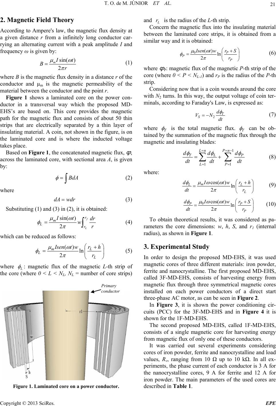 T. O. de M. JÚNIOR ET AL. 21 2. Magnetic Field Theory According to Ampere's law, the magnetic flux density at a given distance r from a infinitely long conductor car- rying an alternating current with a peak amplitude I and frequency ω is given by: sin( ) 2 m I t Br (1) where B is the magnetic flux density in a distance r of the conductor and µm is the magnetic permeability of the material between the conductor and the point r. Figure 1 shows a laminated core on the power con- ductor in a transversal way which the proposed MD- EHS’s are based on. This core provides the magnetic path for the magnetic flux and consists of about 50 thin strips that are electrically separated by a thin layer of insulating material. A coin, not shown in the figure, is on the laminated core and is where the inducted voltage takes place. Based on Figure 1, the concatenated magnetic flux, ϕ , across the laminated core, with sectional area A, is given by: BdA (2) where dA wdr (3) Substituting (1) and (3) in (2), it is obtained: sin( ) 2 f L r m Lr It dr wr (4) which can be reduced as follows: ()ln 2 mL L L Isent wrh r (5) where L : magnetic flux of the magnetic L-th strip of the core (where 0 < L < NL, NL = number of core strips) P rimary conductor Figure 1. Laminated cor e on a power conductor. and L r is the radius of the L-th strip. Concern the magnetic flux into the insulating material between the laminated core strips, it is obtained from a similar way and it is obtained: 0()ln 2 P P P Isent wrS r (6) where ϕ P: magnetic flux of the magnetic P-th strip of the core (where 0 < P < NL-1) and rP is the radius of the P-th strip. Considering now that is a coin wounds around the core with N2 turns. In this way, the output voltage of coin ter- minals, according to Faraday's Law, is expressed as: 2T S d VN dt (7) where T is the total magnetic flux. T can be ob- tained by the summation of the magnetic flux through the magnetic and insulating blades: 1 11 Ln Pn TL LP dd d dt dtdt P (8) where: cos() ln 2 m LL L Itw dr dt r h (9) 0cos()ln 2 PP P Itw dr dt r S (10) To obtain theoretical results, it was considered as pa- rameters the core dimensions: w, h, S, and r1 (internal radius), as shown in Figure 1. 3. Experimental Study In order to design the proposed MD-EHS, it was used magnetic cores of three different materials: iron powder, ferrite and nanocrystalline. The first proposed MD-EHS, called 3F-MD-EHS, consists of harvesting energy from magnetic flux through three symmetrical magnetic cores installed on each power conductors of a direct start three-phase AC motor, as can be seen in Figure 2. In Figure 3, it is shown the power conditioning cir- cuits (PCC) for the 3F-MD-EHS and in Figure 4 it is shown for the 1F-MD-EHS. The second proposed MD-EHS, called 1F-MD-EHS, consists of a single magnetic core for harvesting energy from magnetic flux of only one of these conductors. It was carried out several experiments considering cores of iron powder, ferrite and nanocrystalline and load values, Rv, ranging from 10 up to 10 k. In all ex- periments, the phase current of each conductor is 3 A for the nanocrystalline cores, 9 A for ferrite and 12 A for iron powder. The main parameters of the used cores are described in Table 1. Copyright © 2013 SciRes. EPE 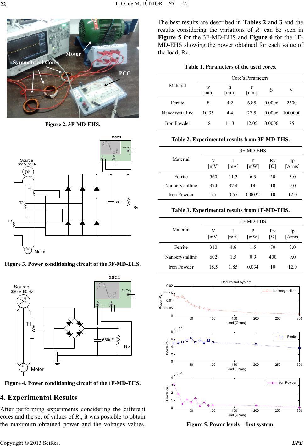 T. O. de M. JÚNIOR ET AL. 22 Motor S y mmetrical Cores PCC Figure 2. 3F-MD-EHS. Motor M Source 380 V 60 Hz 3PH T1 T2 T3 680uF Rv XSC1 AB Ext Trig + + _ _+_ Figure 3. Power conditioning circuit of the 3F-MD-EHS. Motor M Source 380 V 60 Hz 3PH T1 680uF Rv XSC1 AB Ext Trig + + _ _+_ Figure 4. Power conditioning circuit of the 1F-MD-EHS. 4. Experimental Results After performing experiments considering the different cores and the set of values of Rv, it was possible to obtain the maximum obtained power and the voltages values. The best results are described in Tables 2 and 3 and the results considering the variations of Rv can be seen in Figure 5 for the 3F-MD-EHS and Figure 6 for the 1F- MD-EHS showing the power obtained for each value of the load, Rv. Table 1. Parameters of the used cores. Core’s Parameters Material w [mm] h [mm] r [mm] S r Ferrite 8 4.2 6.85 0.00062300 Nanocrystalline10.35 4.4 22.5 0.00061000000 Iron Powder 18 11.3 12.05 0.000675 Table 2. Experimental results from 3F-MD-EHS. 3F-MD-EHS Material V [mV] I [mA] P [mW] Rv [] Ip [Arms] Ferrite 560 11.3 6.3 50 3.0 Nanocrystalline 374 37.4 14 10 9.0 Iron Powder 5.7 0.57 0.0032 10 12.0 Table 3. Experimental results from 1F-MD-EHS. 1F-MD-EHS Material V [mV] I [mA] P [mW] Rv [] Ip [Arms] Ferrite 310 4.6 1.5 70 3.0 Nanocrystalline 602 1.5 0.9 400 9.0 Iron Powder 18.5 1.85 0.034 10 12.0 50100 150 200 250 300 0 2 4 6 8x 10 -3 Load (Ohms) P ower (W ) Ferrite 50100 150 200 250 300 0 0.005 0.01 0.015 0.02 Load (Ohms) P ower (W) Results first system Nanocrystalline 50100 150 200 250 300 0 1 2 3 4x 10 -6 Load (Ohms) P ower (W) Iron Powder Figure 5. Power levels – first system. Copyright © 2013 SciRes. EPE 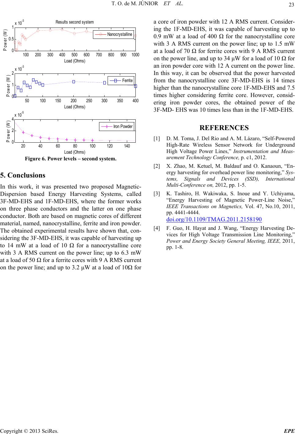 T. O. de M. JÚNIOR ET AL. Copyright © 2013 SciRes. EPE 23 50 100150 200 250300 350 400 0 1 2x 10 -3 Load (Ohm s) Power (W) Ferrite 100 200 300400 500 600 700 800 9001000 0 0. 5 1x 10 -3 Load (Ohm s) Power (W) Res ul t s second system Nanocrystalline 20 406080100120140 0 2 4x 10 -5 Load (Ohm s) Pow er (W) Iron P owder Figure 6. Power levels – second system. 5. Conclusions In this work, it was presented two proposed Magnetic- Dispersion based Energy Harvesting Systems, called 3F-MD-EHS and 1F-MD-EHS, where the former works on three phase conductors and the latter on one phase conductor. Both are based on magnetic cores of different material, named, nanocrystalline, ferrite and iron powder. The obtained experimental results have shown that, con- sidering the 3F-MD-EHS, it was capable of harvesting up to 14 mW at a load of 10 for a nanocrystalline core with 3 A RMS current on the power line; up to 6.3 mW at a load of 50 for a ferrite cores with 9 A RMS current on the power line; and up to 3.2 W at a load of 10 for a core of iron powder with 12 A RMS current. Consider- ing the 1F-MD-EHS, it was capable of harvesting up to 0.9 mW at a load of 400 for the nanocrystalline core with 3 A RMS current on the power line; up to 1.5 mW at a load of 70 for ferrite cores with 9 A RMS current on the power line, and up to 34 W for a load of 10 for an iron powder core with 12 A current on the power line. In this way, it can be observed that the power harvested from the nanocrystalline core 3F-MD-EHS is 14 times higher than the nanocrystalline core 1F-MD-EHS and 7.5 times higher considering ferrite core. However, consid- ering iron powder cores, the obtained power of the 3F-MD- EHS was 10 times less than in the 1F-MD-EHS. REFERENCES [1] D. M. Toma, J. Del Rio and A. M. Lázaro, “Self-Powered High-Rate Wireless Sensor Network for Underground High Voltage Power Lines,” Instrumentation and Meas- urement Technology Conference, p. c1, 2012. [2] X. Zhao, M. Ketuel, M. Baldauf and O. Kanaoun, “En- ergy harvesting for overhead power line monitoring,” Sys- tems, Signals and Devices (SSD), International Multi-Conference on, 2012, pp. 1-5. [3] K. Tashiro, H. Wakiwaka, S. Inoue and Y. Uchiyama, “Energy Harvesting of Magnetic Power-Line Noise,” IEEE Transactions on Magnetics, Vol. 47, No.10, 2011, pp. 4441-4444. doi.org/10.1109/TMAG.2011.2158190 [4] F. Guo, H. Hayat and J. Wang, “Energy Harvesting De- vices for High Voltage Transmission Line Monitoring,” Power and Energy Society General Meeting, IEEE, 2011, pp. 1-8. |