

Paper Menu >>
Journal Menu >>
 Energy and Power Engineering, 2013, 5, 11-14 doi:10.4236/epe.2013.53B003 Published Online May 2013 (http://www.scirp.org/journal/epe) Optical Design of OCT with Gapp ed Magnetic Ring* Xiaoyi Su, Qifeng Xu College of Electrical Engineering and Automation, Fuzhou University, Fuzhou, China Email: [email protected] Received 2013 ABSTRACT The mathematics and physics model of OCT (Optical Current Transformer) with a gapped magnetic ring is briefly dis- cussed in the paper. And some proposals of how to select the magnetic materials and crystals and reduce the stress bire- fringence of the crystal are also put forward in the paper. Based on the above, an OCT with 1000 A rated current is de- signed by using the ANSOFT Maxwell tools. Keywords: Ferromagnetic Collector Type; Optics Current Transformer; Magnetic Properties; Linear Birefringence 1. Introduction Faraday magneto-optical effect is applied in optical cur- rent transformer (OCT). Based on its sensing methodol- ogy it can be divided into four types: fiber one, bulk glass one, solenoid one, as well as gapped magnetic ring one [1]. The one with a gapped magnetic ring utilizes a small piece of magneto-optic crystal and other optical elements to be placed in the gap of the magnetic ring wounding around a current carrying conductor to form an optical circuit. The gap magnetically induced by the cur- rent flowing in the conductor and the crystal are the “heart” of an optical current transformer head. Taken together, the magnetic properties and the optical proper- ties should be taken into consideration in the design. This paper discusses the characteristics of the OCT with gapped magnetic ring. Additionally, reasons and proce- dures to select magnetic materials and crystals and miti- gate stress birefringence are also represented specifically in the paper. Depending on the analysis above and the ANSOFT Maxwell tools, the optimized structure of an OCT with 1000A has been achieved. 2. The Characteristics of OCT with Gapped Magnetic Ring When a linearly polarized light passes through a mag- netic field paralleling to its propagation direction, a opti- cal phase shift of the light called Faraday rotation angle will created due to the Faraday effect VHdl (1) where V is the Verdet constant. Once deemed if a gap of magnetic ring is small enough, the gap magnetic can be regarded as same as the ring inherent magnetic induced by the current flowing in the conductor. Additionally, based on the Ampere circuital theorem the gap magnetic strength is given by () g ggaa H Il ulu (2) where l is the polarized light effective optical passing path in the gap, I is the primary current, lg is the air-gap length, ug is the air permeability, ua is the gapped mag- netic ring permeability, la is the gapped magnetic ring average loop length. As ug is far less than ua, Equation (1) is simplified as g g H Il (3) Combined Equation (1) with Equatio n (3), the Faraday deflection angle θ and the primary current I are given by g cg VHdluVIl l (4) g gc I luVl (5) in which lc is the crystal length. Set Pi to be the polarizer output light intensity and P0 to be the analyzer output light intensity. According to the Malus law, the relation- ship between Pi and P0 is expressed as 2 0cos () i PaP (6) where α is the optical attenuation coefficient intensity; φ is the difference optical phase shift between the two out- put light waves. Desiring to obtain the maximum outpu t power, φ is set to 45°. If θ is small enough, sin2θ will approximately equal to 2θ. Equation (6) transforms into 0 2 (1 ) 2 gc iD g uVIl a PP PP l CAC (7) *Project supported by the National Natural Science Foundation of China (51177016). Copyright © 2013 SciRes. EPE 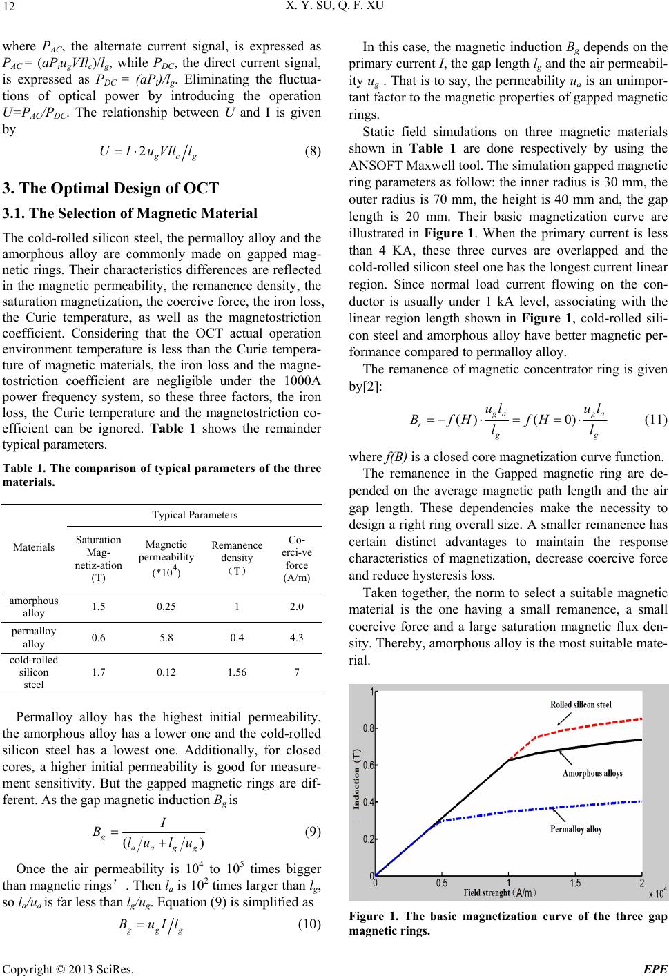 X. Y. SU, Q. F. XU 12 where PAC, the alternate current signal, is expressed as PAC = (aPiugVIlc)/lg, while PDC, the direct current signal, is expressed as PDC = (aPi)/lg. Eliminating the fluctua- tions of optical power by introducing the operation U=PAC/PDC. The relationship between U and I is given by 2 g cg UIuVIll (8) 3. The Optimal Design of OCT 3.1. The Selection of Magnetic Material The cold-rolled silicon steel, the permalloy alloy and the amorphous alloy are commonly made on gapped mag- netic rings. Their characteristics differences are reflected in the magnetic permeability, the remanence density, the saturation magnetization, the coercive force, the iron loss, the Curie temperature, as well as the magnetostriction coefficient. Considering that the OCT actual operation environment temperature is less than the Curie tempera- ture of magnetic materials, the iron loss and the magne- tostriction coefficient are negligible under the 1000A power frequency system, so these three factors, the iron loss, the Curie temperature and the magnetostriction co- efficient can be ignored. Table 1 shows the remainder typical parameters. Table 1. The comparison of typical parameters of the three materials. Typical Parameters Materials Saturation Mag- netiz-ation (T) Magnetic permeability (*104) Remanence density (T) Co- erci-ve force (A/m) amorphous alloy 1.5 0.25 1 2.0 permalloy alloy 0.6 5.8 0.4 4.3 cold-rolled silicon steel 1.7 0.12 1.56 7 Permalloy alloy has the highest initial permeability, the amorphous alloy has a lower one and the cold-rolled silicon steel has a lowest one. Additionally, for closed cores, a higher initial permeability is good for measure- ment sensitivity. But the gapped magnetic rings are dif- ferent. As the gap magnetic induction Bg is () g aag g I Blu lu (9) Once the air permeability is 104 to 105 times bigger than magnetic rings’. Then la is 102 times larger than lg, so la/ua is far less than lg/ug. Equation (9) is simplified as g gg BuIl (10) In this case, the magnetic indu pr ction Bg depends on the imary current I, the gap length lg and the air permeabil- ity ug . That is to say, the permeability ua is an unimpor- tant factor to the magnetic properties of gapped magnetic rings. Static field simulations on three magnetic materials shown in Table 1 are done respectively by using the ANSOFT Maxwell tool. The simulation gapped magnetic ring parameters as follow: the inner radius is 30 mm, the outer radius is 70 mm, the height is 40 mm and, the gap length is 20 mm. Their basic magnetization curve are illustrated in Figure 1. When the primary current is less than 4 KA, these three curves are overlapped and the cold-rolled silicon steel one has the lo ngest current linear region. Since normal load current flowing on the con- ductor is usually under 1 kA level, associating with the linear region length shown in Figure 1, cold-rolled sili- con steel and amorphous alloy have better magnetic per- formance compared to permalloy alloy. The remanence of magnetic concentrator ring is given by[2]: ()( 0) g ag r a g g ul ul BfH fH ll (11) where f(B) is a closed core magnetization curve function. to select a suitable magnetic The remanence in the Gapped magnetic ring are de- pended on the average magnetic path length and the air gap length. These dependencies make the necessity to design a r ight ring overall size. A smaller remanence has certain distinct advantages to maintain the response characteristics of magnetization, decrease coercive force and reduce hysteresis loss. Taken together, the norm material is the one having a small remanence, a small coercive force and a large saturation magnetic flux den- sity. Thereby, amorphous alloy is the most suitable mate- rial. Figure 1. The basic magnetization curve of the three gap magnetic rin gs. Copyright © 2013 SciRes. EPE 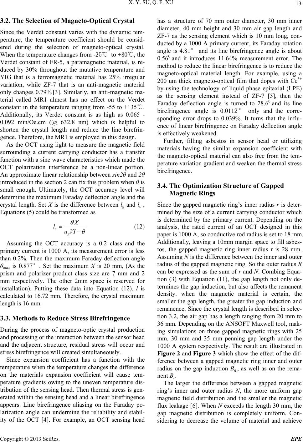 X. Y. SU, Q. F. XU 13 3.2. The Selection of Magneto-Optical Crystal Since the Verdet constant varies with the dynamic tem- perature, the temperature coefficient should be consid- ered during the selection of magneto-optical crystal. When the te mperatu re change s from -2 5℃ to +80℃, the Verdet constant of FR-5, a paramagnetic material, is re- duced by 30% throughout the mutative temperature and YIG that is a ferromagnetic material has 25% irregular variation, while ZF-7 that is an anti-magnetic material only changes 0.79% [3]. Similarly, an anti-magnetic ma- terial called MR1 almost has no effect on the Verdet constant in the temperature ranging from -55 to +135℃. Additionally, its Verdet constant is as high as 0.065 - 0.092 min/Oe.cm (@ 632.8 nm) which is helpful to shorten the crystal length and reduce the line birefrin- gence. Therefore, the MR1 is employed in this design. As the OCT using light to measure the magnetic field surrounding a current carrying conductor has a transfer function with a sine wave characteristics which made the OCT polarization interference be a non-linear portion. An approximate linear relationship between sin2θ and 2θ introduced in the section 2 can fix th is problem when θ is small enough. Ultimately, the OCT accuracy level will determine the maximum Faraday deflection angle and the crystal length. Set X is the difference between lg and lc , Equations (5) could be transformed as c X l g uV I (12) Assuming the OCT accuracy pr Reduce Stress Birefringence tion ilar expansion coefficient with th mization Structure of Gapped Magnetic Rings eter- mineurrent carrying conductor which ner and outer radius N, the more uniform gap m is a 0.2 class and the imary current is 1000 A, its measurement error is less than 0.2%. Then the maximum Faraday deflection angle θmax is 0.877°. Set the maximum X is 20 mm, (As the prism and polarizer product class size are 7 mm and 2 mm respectively. The other 2mm space is reserved for installation). Putting these data into Equation (12), l is calculated to 16.72 mm. Therefore, the crystal maximum length is 16 mm. 3.3. Methods to During the process of magneto-optic crystal produc and processing or the in teract ion between the sensor head and the adjacent structure, residual stress will occur and stress birefringence will created simultaneously. Since expansion coefficient has a function with the temperature when the temperature ch anges the di fferenc e on the materials expansion coefficient will cause tem- perature gradients owing to the uneven temperature dis- tribution of the sens ing head. Then thermal stress is gen- erated within the sensing head and a linear birefringence appears. Line birefringence aliasing on the Faraday po- larization angle can undermine the reliability and stabil- ity of the OCT [4]. For example, an OCT sensing head has a structure of 70 mm outer diameter, 30 mm inner diameter, 40 mm height and 30 mm air gap length and ZF-7 as the sensing element which is 10 mm long, con- ducted by a 1000 A primary current, its Faraday rotation angle is 4.81° and its line birefringence angle is about 0.560 and it introduces 11.64% measurement error. The method to reduce the linear birefring ence is to reduce the magneto-optical material length. For example, using a 200 um thick magneto-optical film that dopes with Ce3+ by using the technology of liquid phase epitaxial (LPE) as the sensing element instead of ZF-7 [5], then the Faraday deflection angle is turned to 28.60 and its line birefringence angle is 0.0112° only and the corre- sponding error drops to 0.039%. It turns that the influ- ence of linear birefringence on Faraday deflection angle is effectively weakened. Further, filling asbestos in sensor head or utilizing materials having the sim e magneto-optical material can also free from the tem- perature variation gradient and weaken the thermal stress birefringence. 3.4. The Opti Since the gapped magnetic ring’s inner radius r is d d by the size of a c is determined by the primary current. Depending on the analysis, the rated current of an OCT designed in this paper is 1000 A, so conductive rod radius is set to 18 mm. Additionally, leaving a 10mm margin sp ace to fill asbes- tos, the gapped magnetic ring inner radius r is 28 mm. Assuming N is the difference between th e inne r and ou ter radius of the gapped magnetic ring. So the outer radius R can be expressed as the sum of r and N. Combing Equa- tion (3) with Equation (11), the gap length not only de- termines the gap induction, but also affects the remanent density. when the magnetic material is certain, the smaller the gap length, the greater the gap induction and remanence. Since the crystal length is described in selec- tion 3.2, the air gap has a length ranging from 20 mm to 36 mm. Depending on the ANSOFT Maxwell tool, mak- ing simulations on three gapped magnetic rings with 25 mm, 30 mm and 35 mm penning gap length under the 1000 A system respectively. The result are illustrated in Figure 2 and Figure 3 which show the effect of the dif- ference between a gapped magnetic ring inner and outer radius on the gap induction Bg , as well as on the rema- nent Br. The larger the difference between a gapped magnetic ring’s in agnetic field distribution and the smaller the magnetic flux leakage [6]. When N exceeds the length 30 mm, the gap magnetic distribution is completely uniform. Con- sidering to decrease the volume of material and achieve Copyright © 2013 SciRes. EPE 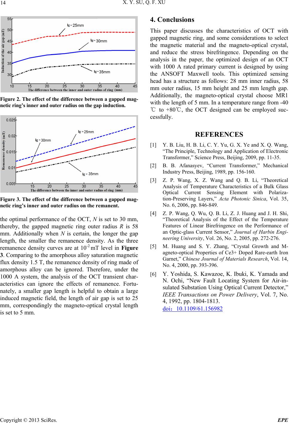 X. Y. SU, Q. F. XU Copyright © 2013 SciRes. EPE 14 4. Conclusions This paper discusses the characteristics of OCT with gapped magnetic ring, and some considerations to select the magnetic material and the magneto-optical crystal, and reduce the stress birefringence. Depending on the analysis in the paper, the optimized design of an OCT with 1000 A rated primary current is designed by using the ANSOFT Maxwell tools. This optimized sensing head has a structure as follows: 28 mm inner radius, 58 mm outer radius, 15 mm height and 25 mm length gap. Additionally, the magneto-optical crystal choose MR1 with the length of 5 mm. In a temperature range from -40 ℃ to +80℃, the OCT designed can be employed suc- cessfully. Figure 2. The effect of the difference between a gapped mag- netic ring’s inner and outer radius on th e gap induction. REFERENCES [1] Y. B. Liu, H. B. Li, C. Y. Yu, G. X. Ye and X. Q. Wang, “The Principle, Technology and Application of Electronic Transformer,” Science Press, Beijing, 2009, pp. 11-35. [2] B. B. Afanasyev, “Current Transformer,” Mechanical Industry Press, Beijing, 1989, pp. 156-160. [3] Z. P. Wang, X. Z. Wang and Q. B. Li, “Theoretical Analysis of Temperature Characteristics of a Bulk Glass Optical Current Sensing Element with Polariza- tion-Preserving Layers,” Acta Photonic Sinica, Vol. 35, No. 6, 2006, pp. 846-849. Figure 3. The effect of the difference between a gapped mag- netic ring’s inner and outer radius on the remanent. 0 mm ereby, the gapped magnetic ring outer radius R is 58 the optimal performance of the OCT, N is set to 3, [4] Z. P. Wang, Q. Wu, Q. B. Li, Z. J. Huang and J. H. Shi, “Theoretical Analysis of the Effect of the Temperature Features of Linear Birefringence on the Performance of an Optic-glass Current Sensor,” Journal of Harbin Engi- neering University, Vol. 26, No. 2, 2005, pp. 272-276. th mm. Additionally when N is certain, the longer the gap length, the smaller the remanence density. As the three remanence density curves are at 10-2 mT level in Figure 3. Comparing to the amorphous alloy saturation magn etic flux density 1.5 T, the remanence density of ring made of amorphous alloy can be ignored. Therefore, under the 1000 A system, the analysis of the OCT transient char- acteristics can ignore the effects of remanence. Fortu- nately, a smaller gap length is helpful to obtain a large induced magnetic field, the length of air gap is set to 25 mm, correspondingly the magneto-optical crystal length is set to 5 mm. [5] M. Huang and S. Y. Zhang, “Crystal Growth and M- agneto-optical Properties of Ce3+ Doped Rare-earth Iron Garnet,” Chinese Journal of Materials Research, Vol. 14, No. 4, 2000, pp. 393-396. [6] Y. Yoshida, S. Kawazoe, K. Ibuki, K. Yamada and N. Ochi, “New Fault Locating System for Air-in- sulated Substation Using Optical Current Detector ,” IEEE Transactions on Power Delivery, Vol. 7, No. 4, 1992, pp. 1804-1813. doi:10.1109/61.156982 |