

Paper Menu >>
Journal Menu >>
 Open Journal of Fluid Dynamics, 2013, 3, 92-99 http://dx.doi.org/10.4236/ojfd.2013.32A015 Published Online July 2013 (http://www.scirp.org/journal/ojfd) Heat Transfer Enhancement of Cu-H2O Nanofluid with Internal Heat Generation Using LBM Mohammad Abu Taher1, Yeon Won Lee2, Heuy Dong Kim1* 1School of Mechanical Engineering, Andong National University, Andong, South Korea 2School of Mechanical Engineering, Pukyong National University, Busan, South Korea Email: *[email protected] Received June 10, 2013; revised June 17, 2013; accepted June 27, 2013 Copyright © 2013 Mohammad Abu Taher et al. This is an open access article distributed under the Creative Commons Attribution License, which permits unrestricted use, distribution, and reproduction in any medium, provided the original work is properly cited. ABSTRACT Fluid flow and heat transfer analysis of Cu-H2O nanofluid in a square cavity using a Thermal Lattice Boltzmann Method (TLBM) have been studied in the present work. The LBM has built up on the D2Q9 model and the single re- laxation time method called the Lattice-BGK (Bhatnagar-Gross-Krook) model. The effect of suspended nanoparticles on the fluid flow and heat transfer analysis have been investigated for different non dimensional parameters such as particle volume fraction (φ) and particle diameters (dp) in presence of internal heat generation (q) of nanoparticles. It is seen that flow behaviors and the average rate of heat transfer in terms of the Nusselt number (Nu) as well as the thermal conductivity of nanofluid are effectively changed with the different controlling parameters such as particle volume frac- tion (2% ≤ φ ≤ 10%), particle diameter (dp = 5 nm to 40 nm) with fixed Rayleigh number, Ra = 105. The present results of the analysis are compared with the previous experimental and numerical results for both pure and nanofluid and it is seen that the agreement is good indeed among the results. Keywords: Nanofluid; Lattice-Boltzmann; Volume Fractions; Particle Diameter; Heat Generation 1. Introduction The term nanofluid is envisioned to describe a solid-liq- uid mixer which consists of nano-sized solid particles and a base liquid and this is one of new challenges for thermo-sciences provided by the nanotechnology. It has potential applications in the microelectromechanical sys- tems (MEMS) and electronics cooling industries. There- fore, in the recent years, the micro and nano systems have become of great interest due to their important and promising applications in various fields. As a result, the research topic of nanofluids has been receiving increased attention worldwide. In fact, numerous theoretical and experimental studies of the effective thermal conductiv- ity of suspensions that contains solid particles have been conducted since Maxwell’s theoretical work was pub- lished more than 100 years ago. All of the studies on thermal conductivity of suspensions have been consid- ered with millimeter to micrometer sized particles. The use of the conventional millimeter and micrometer-sized particles in heat transfer fluids in practical devices is greatly limited by the tendency of such particles to settle rapidly and to clog mini and micro channels. Until now, it is very difficult to solid particles from eventually set- tling out of suspension because of particle size. However, nanoparticles appear to be ideally suited for applications in which fluids flow through small passages, because the nanoparticles are stable and small enough not to clog flow passage. Therefore, the main goal of nanofluids is to achieve the maximum thermal properties with the mini- mum possibility of particle volume fractions (less than 1%) and size of particles (less than 10 nm) by uniform dispersion and stable suspension of nanoparticles in base fluids/liquids. The performance of heat transfer of nan- ofluid depends on more factors such as shape of particles, the dimension of particles, the volume fractions of parti- cle in the suspensions, and the thermal properties of par- ticle materials [1,2]. However, significant amounts of experimental and theoretical work have been performed on buoyancy induced flow in conventional fluid [3,4]. The mechanism of nanoparticles, enhancement of heat transfer characteristics are described more detailedly in the books [5,6] and Yu et al. [7]. From the microscopic point of view, classical me- chanics has no insight into the microstructure of the sub- stance; however, statistical mechanics calculated the *Corresponding author. C opyright © 2013 SciRes. OJFD 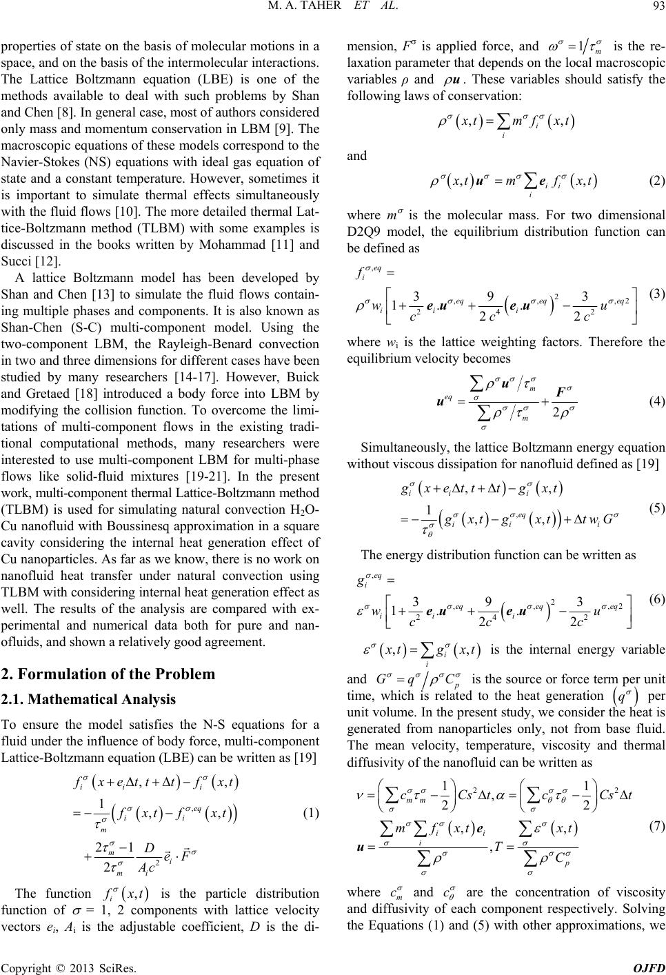 M. A. TAHER ET AL. 93 properties of state on the basis of molecular motions in a space, and on the basis of the intermolecular interactions. The Lattice Boltzmann equation (LBE) is one of the methods available to deal with such problems by Shan and Chen [8]. In general case, most of authors considered only mass and momentum conservation in LBM [9]. The macroscopic equations of these models correspond to the Navier-Stokes (NS) equations with ideal gas equation of state and a constant temperature. However, sometimes it is important to simulate thermal effects simultaneously with the fluid flows [10]. The more detailed thermal Lat- tice-Boltzmann method (TLBM) with some examples is discussed in the books written by Mohammad [11] and Succi [12]. A lattice Boltzmann model has been developed by Shan and Chen [13] to simulate the fluid flows contain- ing multiple phases and components. It is also known as Shan-Chen (S-C) multi-component model. Using the two-component LBM, the Rayleigh-Benard convection in two and three dimensions for different cases have been studied by many researchers [14-17]. However, Buick and Gretaed [18] introduced a body force into LBM by modifying the collision function. To overcome the limi- tations of multi-component flows in the existing tradi- tional computational methods, many researchers were interested to use multi-component LBM for multi-phase flows like solid-fluid mixtures [19-21]. In the present work, multi-component thermal Lattice-Boltzmann method (TLBM) is used for simulating natural convection H2O- Cu nanofluid with Boussinesq approximation in a square cavity considering the internal heat generation effect of Cu nanoparticles. As far as we know, there is no work on nanofluid heat transfer under natural convection using TLBM with considering internal heat generation effect as well. The results of the analysis are compared with ex- perimental and numerical data both for pure and nan- ofluids, and shown a relatively good agreement. 2. Formulation of the Problem 2.1. Mathematical Analysis To ensure the model satisfies the N-S equations for a fluid under the influence of body force, multi-component Lattice-Boltzmann equation (LBE) can be written as [19] , 2 ,, 1, 21 2 ii i eq ii m m i mi , f xetttfxt f xt fxt DeF Ac (1) The function , i f xt is the particle distribution function of = 1, 2 components with lattice velocity vectors ei, Ai is the adjustable coefficient, D is the di- mension, F is applied force, and 1m is the re- laxation parameter that depends on the local macroscopic variables ρ and u. These variables should satisfy the following laws of conservation: ,, i i x tmfx t and ,, ii i x tmfx uet (2) where m is the molecular mass. For two dimensional D2Q9 model, the equilibrium distribution function can be defined as , 2 ,, 24 2 39 3 1. . 22 eq i ,2eq eq ii i f wu cc c eq (3) eueu where wi is the lattice weighting factors. Therefore the equilibrium velocity becomes 2 m eq m uF u (4) Simultaneously, the lattice Boltzmann energy equation without viscous dissipation for nanofluid defined as [19] , ,, 1,, ii ei eq ii i gxttt gxt g xt gxttwG (5) The energy distribution function can be written as , 2 ,, 24 2 39 3 1. . 22 eq i ,2 eq eq ii i g wu cc c eq (6) eueu , i , i x tgx t is the internal energy variable and p Gq C is the source or force term per unit time, which is related to the heat generation q per unit volume. In the present study, we consider the heat is generated from nanoparticles only, not from base fluid. The mean velocity, temperature, viscosity and thermal diffusivity of the nanofluid can be written as 22 11 , 22 ,, , mm ii i p cCstcCs mf xtxt TC t e u (7) where m c and c are the concentration of viscosity and diffusivity of each component respectively. Solving the Equations (1) and (5) with other approximations, we Copyright © 2013 SciRes. OJFD 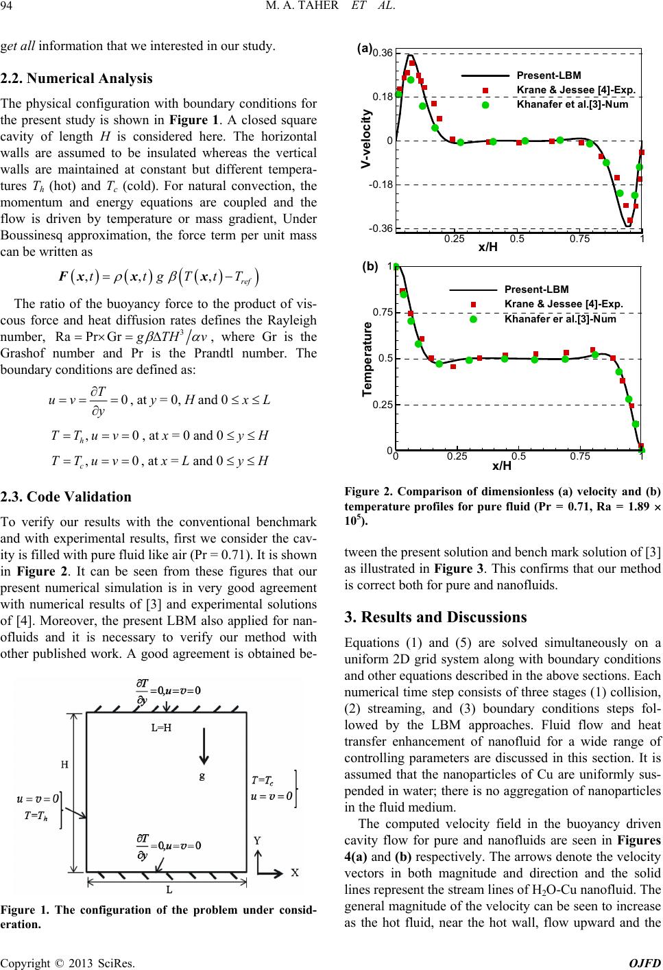 M. A. TAHER ET AL. 94 get all information that we interested in our study. 0.25 0.5 0.751 -0.36 -0.18 0 0.18 2.2. Numerical Analysis boundary conditions for The ratio of the buoyancy force to the product of vis- co The physical configuration with the present study is shown in Figure 1. A closed square cavity of length H is considered here. The horizontal walls are assumed to be insulated whereas the vertical walls are maintained at constant but different tempera- tures Th (hot) and Tc (cold). For natural convection, the momentum and energy equations are coupled and the flow is driven by temperature or mass gradient, Under Boussinesq approximation, the force term per unit mass can be written as ,tFx , , ref tgTtT xx us force and heat diffusion rates defines the Rayleigh number, 3 RaPr Gr g TH v , where Gr is the Grashof ndtl number. The boundary conditions are defined as: number and Pr is the Pra 0 T uv y , at y = 0, H and 0 x L , at x = 0 and 0 y H 0 2.3. Code Validation th the conventional benchmark ,0 h TTuv , c TTuv, at x = L and 0 y H To verify our results wi and with experimental results, first we consider the cav- ity is filled with pure fluid like air (Pr = 0.71). It is shown in Figure 2. It can be seen from these figures that our present numerical simulation is in very good agreement with numerical results of [3] and experimental solutions of [4]. Moreover, the present LBM also applied for nan- ofluids and it is necessary to verify our method with other published work. A good agreement is obtained be- 0.36 (a) Present-LBM Krane &Jessee[4]-Exp. Khanafer et al.[3]-Num x/H V-velocity 00.25 0.5 0.75 1 0 0.25 0.5 0.75 1 Present- LBM Krane & Jessee [4]-Exp. Khanafer er al.[3]-Num x/H Temperature (b) Figure 2. Comparison of dimensionless (a) velocity and (b) temperature profiles for pure fluid (Pr = 0.71, Ra = 1.89 the present solution and bench mark solution of [3] simultaneously on a 105). tween as illustrated in Figure 3. This confirms that our method is correct both for pure and nanofluids. 3. Results and Discussions Equations (1) and (5) are solved uniform 2D grid system along with boundary conditions and other equations described in the above sections. Each numerical time step consists of three stages (1) collision, (2) streaming, and (3) boundary conditions steps fol- lowed by the LBM approaches. Fluid flow and heat transfer enhancement of nanofluid for a wide range of controlling parameters are discussed in this section. It is assumed that the nanoparticles of Cu are uniformly sus- pended in water; there is no aggregation of nanoparticles in the fluid medium. The computed velocity field in the buoyancy driven cavity flow for pure and nanofluids are seen in Figures 4(a) and (b) respectively. The arrows denote the velocity vectors in both magnitude and direction and the solid lines represent the stream lines of H2O-Cu nanofluid. The general magnitude of the velocity can be seen to increase as the hot fluid, near the hot wall, flow upward and the Figure 1. The configuration of the problem under cons- eration. id Copyright © 2013 SciRes. OJFD 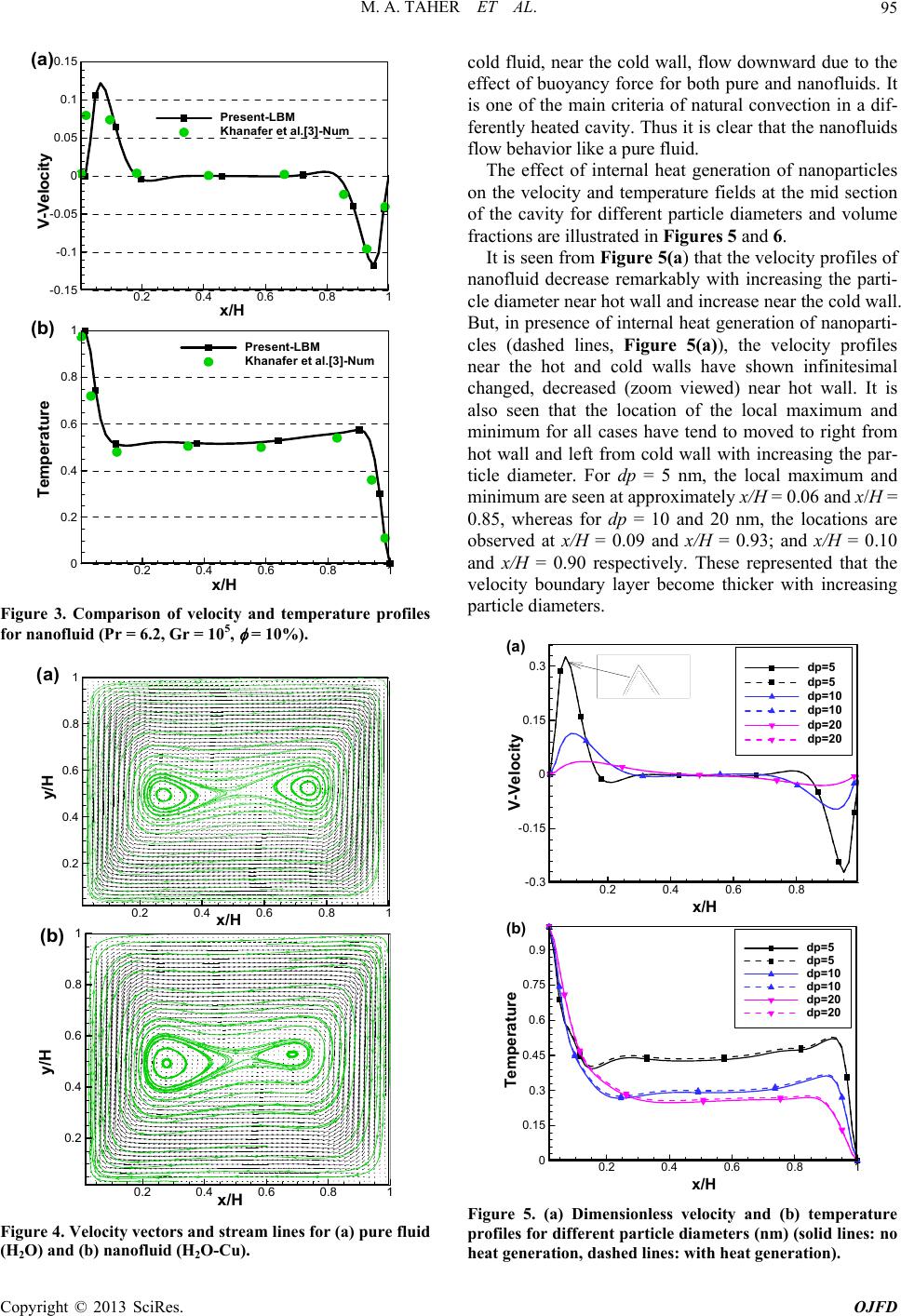 M. A. TAHER ET AL. 95 0.2 0.4 0.6 0.8 1 -0.15 -0.1 -0.05 0 0.05 0.1 0.15 Present-LBM Khanaferetal.[3]-Num ( a ) x / H V-Velocity 0.2 0.4 0.6 0.8 1 0 0.2 0.4 0.6 0.8 1Present-LBM Khanafer et al.[3]-Num ( b ) x / H Temperature Figure 3. Comparison of velocity and temperature profiles for nanofluid (Pr = 6.2, Gr = 105, = 10%). 0.2 0.4 0.6 0.81 0.2 0.4 0.6 0.8 1 x / H y/H ( a ) 0.2 0.40.6 0.81 0.2 0.4 0.6 0.8 1 x/H y/H ( b ) Figure 4. Velocity vectors and stream lines for (a) pure fluid (H2O) and (b) nanofluid (H2O-Cu). pure and nanofluids. It of ing the parti- cl cold fluid, near the cold wall, flow downward due to the effect of buoyancy force for both is one of the main criteria of natural convection in a dif- ferently heated cavity. Thus it is clear that the nanofluids flow behavior like a pure fluid. The effect of internal heat generation of nanoparticles on the velocity and temperature fields at the mid section the cavity for different particle diameters and volume fractions are illustrated in Figures 5 and 6. It is seen from Figure 5(a) that the velocity profiles of nanofluid decrease remarkably with increas e diameter near hot wall and increase near the cold wall. But, in presence of internal heat generation of nanoparti- cles (dashed lines, Figure 5(a)), the velocity profiles near the hot and cold walls have shown infinitesimal changed, decreased (zoom viewed) near hot wall. It is also seen that the location of the local maximum and minimum for all cases have tend to moved to right from hot wall and left from cold wall with increasing the par- ticle diameter. For dp = 5 nm, the local maximum and minimum are seen at approximately x/H = 0.06 and x/H = 0.85, whereas for dp = 10 and 20 nm, the locations are observed at x/H = 0.09 and x/H = 0.93; and x/H = 0.10 and x/H = 0.90 respectively. These represented that the velocity boundary layer become thicker with increasing particle diameters. 0.2 0.4 0.6 0.8 -0.3 -0.15 0 0.15 0.3 dp=5 dp=5 dp=10 dp=10 dp=20 dp=20 x/H (a) V-Velocity 0.2 0.4 0.6 0.8 1 0 0.15 0.3 0.45 0.6 0.75 0.9 dp=5 dp=5 dp=10 dp=10 dp=20 dp=20 x / H (b) Temperature Figure 5. (a) Dimensionless velocity and (b) temperature profiles for different particle diameters (nm) (solid lineo heat generation, dashed lines: with heat generation). s: n Copyright © 2013 SciRes. OJFD 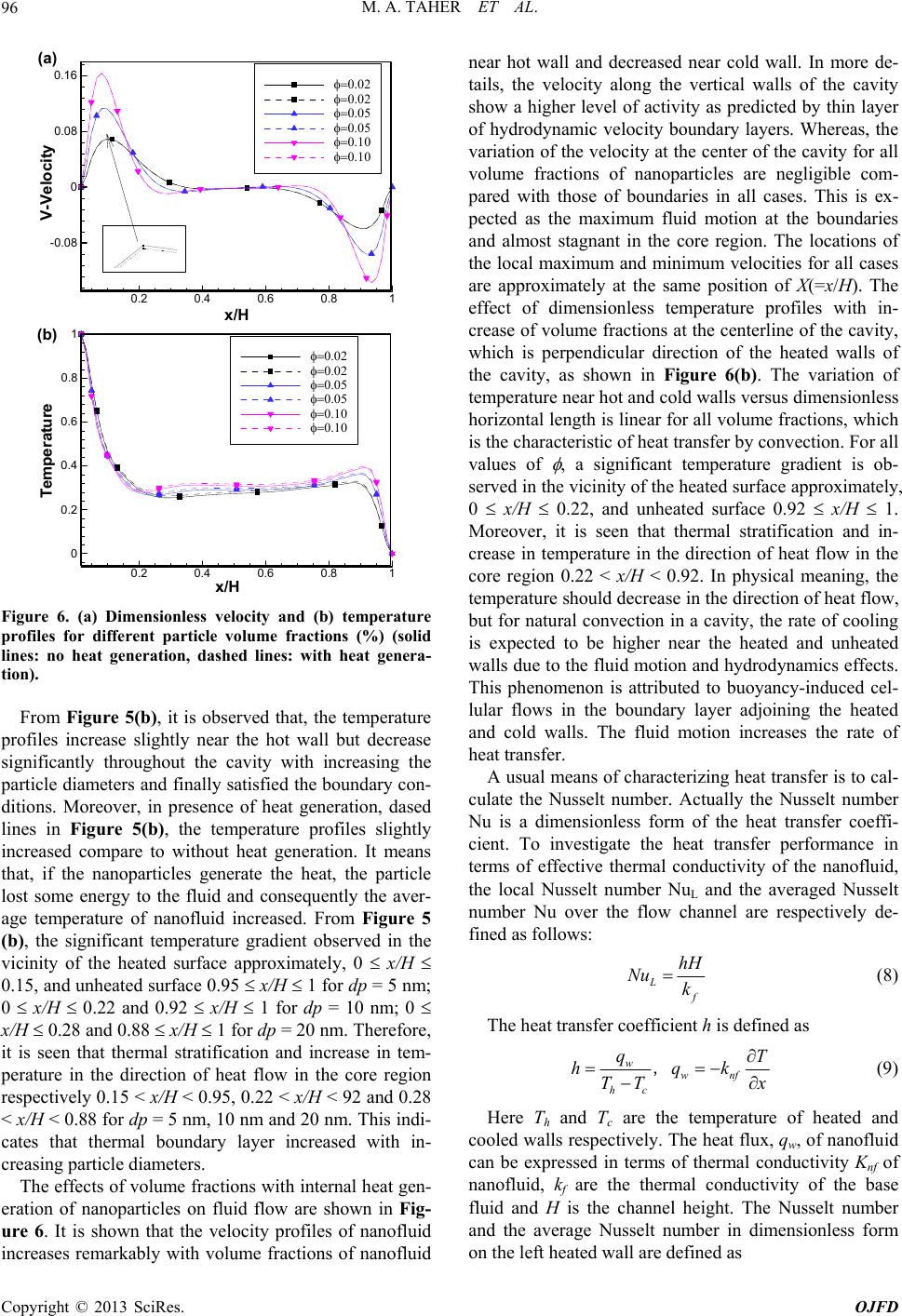 M. A. TAHER ET AL. 96 0.2 0.4 0.6 0.8 1 -0.08 0 0.08 0.16 (a) x/H V-Velocity 0.2 0.4 0.6 0.8 1 0 0.2 0.4 0.6 0.8 1 x / H (b) Temperature Figure 6. (a) Dimensionless velocity and (b) temperature profiles for different particle volume fractions (%) ( lines: no heat generation, dashed lines: with heat genra- s increase slightly near the hot wall but decrease g in sionless form of the heat transfer coeffi- ci solid e tion). From Figure 5(b), it is observed that, the temperature profile si nificantly throughout the cavity with increasing the particle diameters and finally satisfied the boundary con- ditions. Moreover, in presence of heat generation, dased lines in Figure 5(b), the temperature profiles slightly increased compare to without heat generation. It means that, if the nanoparticles generate the heat, the particle lost some energy to the fluid and consequently the aver- age temperature of nanofluid increased. From Figure 5 (b), the significant temperature gradient observed in the vicinity of the heated surface approximately, 0 x/H 0.15, and unheated surface 0.95 x/H 1 for dp = 5 nm; 0 x/H 0.22 and 0.92 x/H 1 for dp = 10 nm; 0 x/H 0.28 and 0.88 x/H 1 for dp = 20 nm. Therefore, it is seen that thermal stratification and increase in tem- perature in the direction of heat flow in the core region respectively 0.15 < x/H < 0.95, 0.22 < x/H < 92 and 0.28 < x/H < 0.88 for dp = 5 nm, 10 nm and 20 nm. This indi- cates that thermal boundary layer increased with in- creasing particle diameters. The effects of volume fractions with internal heat gen- eration of nanoparticles on fluid flow are shown in Fig- ure 6. It is shown that the velocity profiles of nanofluid creases remarkably with volume fractions of nanofluid near hot wall and decreased near cold wall. In more de- tails, the velocity along the vertical walls of the cavity show a higher level of activity as predicted by thin layer of hydrodynamic velocity boundary layers. Whereas, the variation of the velocity at the center of the cavity for all volume fractions of nanoparticles are negligible com- pared with those of boundaries in all cases. This is ex- pected as the maximum fluid motion at the boundaries and almost stagnant in the core region. The locations of the local maximum and minimum velocities for all cases are approximately at the same position of X(=x/H). The effect of dimensionless temperature profiles with in- crease of volume fractions at the centerline of the cavity, which is perpendicular direction of the heated walls of the cavity, as shown in Figure 6(b). The variation of temperature near hot and cold walls versus dimensionless horizontal length is linear for all volume fractions, which is the characteristic of heat transfer by convection. For all values of , a significant temperature gradient is ob- served in the vicinity of the heated surface approximately, 0 x/H 0.22, and unheated surface 0.92 x/H 1. Moreover, it is seen that thermal stratification and in- crease in temperature in the direction of heat flow in the core region 0.22 < x/H < 0.92. In physical meaning, the temperature should decrease in the direction of heat flow, but for natural convection in a cavity, the rate of cooling is expected to be higher near the heated and unheated walls due to the fluid motion and hydrodynamics effects. This phenomenon is attributed to buoyancy-induced cel- lular flows in the boundary layer adjoining the heated and cold walls. The fluid motion increases the rate of heat transfer. A usual means of characterizing heat transfer is to cal- culate the Nusselt number. Actually the Nusselt number Nu is a dimen ent. To investigate the heat transfer performance in terms of effective thermal conductivity of the nanofluid, the local Nusselt number NuL and the averaged Nusselt number Nu over the flow channel are respectively de- fined as follows: L f hH Nu k (8) The heat transfer coefficient h is defined as w wnf hc TT x q hqk T , (9) Here T h and T c are the temperature of heated and cooled walls respectively. The heat flux can be expressed in terms of thermal conductivity Knf of na , qw, of nanofluid nofluid, kf are the thermal conductivity of the base fluid and H is the channel height. The Nusselt number and the average Nusselt number in dimensionless form on the left heated wall are defined as Copyright © 2013 SciRes. OJFD 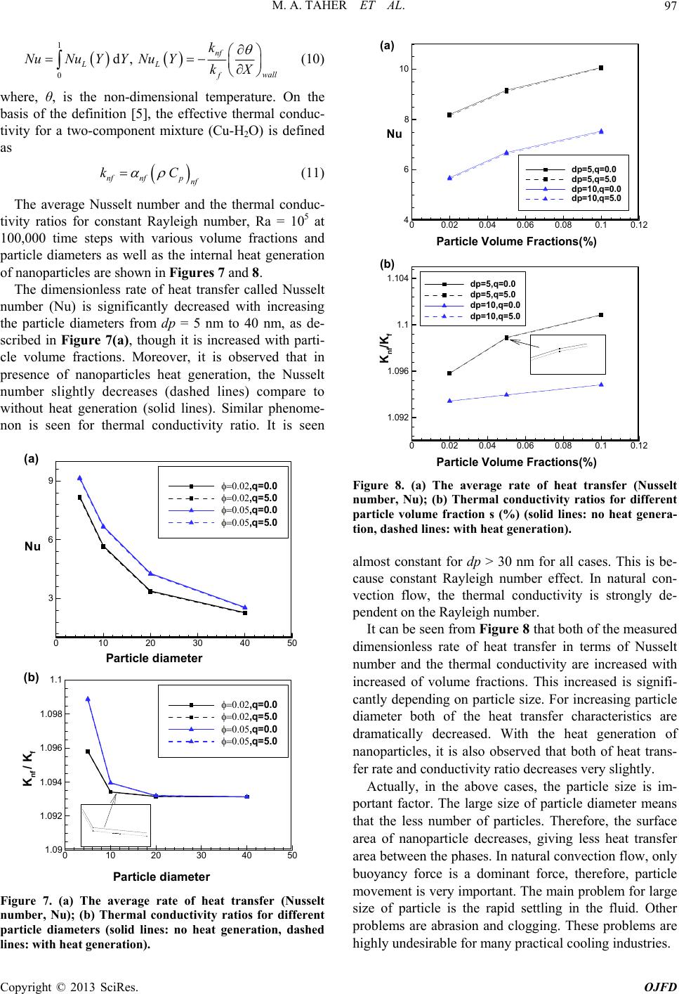 M. A. TAHER ET AL. 97 1 0 d, nf LL wall f k NuNu YYNu YkX (10) where, θ, is the non-dimensional temperature. On the basis of the definition [5], the effective thermal tivity for a two-component mixture (Cu-H2O) is defined verage Nusselt number and the thermal conduc- tivity ratios for constant Rayleigh5 100,000 time steps with various pa conduc- as nfnfp nf kC (11) The a number, Ra = 10 at volume fractions and rticle diameters as well as the internal heat generation of nanoparticles are shown in Figures 7 and 8. The dimensionless rate of heat transfer called Nusselt number (Nu) is significantly decreased with increasing the particle diameters from dp = 5 nm to 40 nm, as de- scribed in Figure 7(a), though it is increased with parti- cle volume fractions. Moreover, it is observed that in presence of nanoparticles heat generation, the Nusselt number slightly decreases (dashed lines) compare to without heat generation (solid lines). Similar phenome- non is seen for thermal conductivity ratio. It is seen 010 20 30 40 50 3 6 9 ,q=0.0 ,q=5.0 ,q=0.0 ,q=5.0 Nu Particlediameter (a) 010 20 30 40 50 1.09 1.092 1.094 1.096 1.098 1.1 ,q=0 .0 ,q=5 .0 ,q=0 .0 ,q=5 .0 K nf /K f Particle diameter (b) 00.02 0.04 0.06 0.080.10.12 4 6 8 10 (a) dp=5,q=0.0 dp=5,q=5.0 dp=1 0,q=0.0 dp=1 0,q=5.0 Nu Particle Volume Fractions(%) 00.02 0.040.06 0.080.10.12 1.092 1.096 1.1 1.104 dp=5,q=0.0 dp=5,q=5.0 dp=10,q=0.0 dp=10,q=5.0 Particle Volume Fractions(%) (b) K nf /K f Figure 8. (a) The average rate of heat transfer (Nusselt number, Nu); (b) Thermal conductivity ratios for different particle volume fraction s (%) (solid lines: no heat genera- tion, dashed lines: with heat generation). ity are increased with in ce ar highly undesirable for many practical cooling industries. almost constant for dp > 30 nm for all cases. This is be- cause constant Rayleigh number effect. In natural con- ection flow, the thermal conductivity is strongly de-v pendent on the Rayleigh number. It can be seen from Figure 8 that both of the measured dimensionless rate of heat transfer in terms of Nusselt number and the thermal conductiv creased of volume fractions. This increased is signifi- cantly depending on particle size. For increasing particle diameter both of the heat transfer characteristics are dramatically decreased. With the heat generation of nanoparticles, it is also observed that both of heat trans- fer rate and conductivity ratio decreases very slightly. Actually, in the above cases, the particle size is im- portant factor. The large size of particle diameter means that the less number of particles. Therefore, the surfa ea of nanoparticle decreases, giving less heat transfer area between the phases. In natural convection flow, only buoyancy force is a dominant force, therefore, particle movement is very important. The main problem for large size of particle is the rapid settling in the fluid. Other problems are abrasion and clogging. These problems are Figure 7. (a) The average rate of heat transfer (Nusselt number, Nu); (b) Thermal conductivity ratios for different particle diameters (solid lines: no heat generation, dashed lines: with heat generation) . Copyright © 2013 SciRes. OJFD 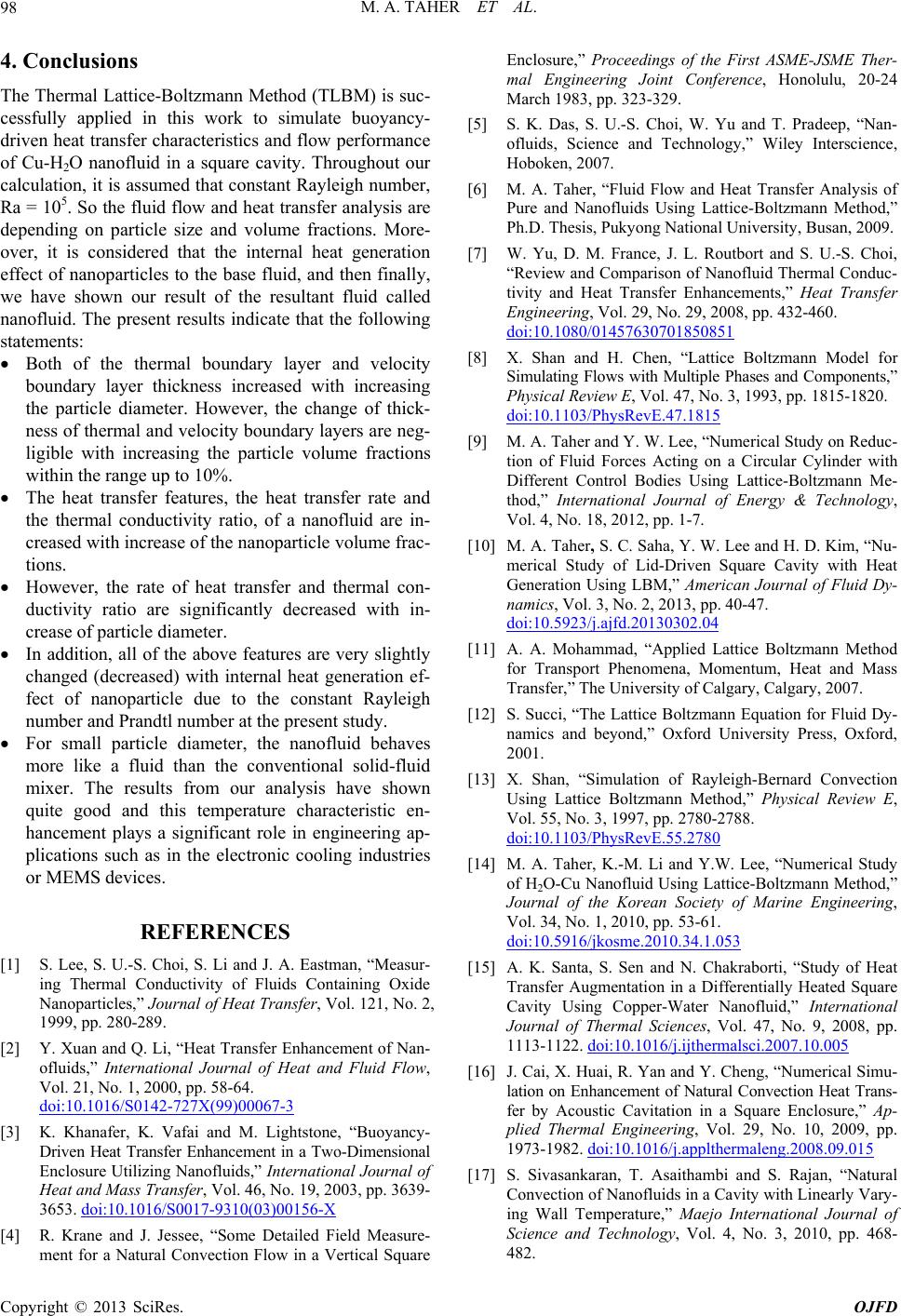 M. A. TAHER ET AL. 98 4. Conclusions The Thermal Lattice-Boltzmann Method (TLBM) is suc- cessfully applied in this work to simulate buoyancy- driven heat transfer characteristics and flow performance of Cu-H2O nanoflui calculation, it is ass d in a square cavity. Throughout our umed that constant Rayleigh number, ith increasing the particle volume fractions ansfer and thermal con- d (decreased) with internal heat generation r, the nanofluid behaves nal of Heat Transfer, Vol. 121, No. 2, 1999, pp. 280-289. [2] Y. Xuan and Qhancement of Nan- Ra = 105. So the fluid flow and heat transfer analysis are depending on particle size and volume fractions. More- over, it is considered that the internal heat generation effect of nanoparticles to the base fluid, and then finally, we have shown our result of the resultant fluid called nanofluid. The present results indicate that the following statements: Both of the thermal boundary layer and velocity boundary layer thickness increased with increasing the particle diameter. However, the change of thick- ness of thermal and velocity boundary layers are neg- ligible w within the range up to 10%. The heat transfer features, the heat transfer rate and the thermal conductivity ratio, of a nanofluid are in- creased with increase of the nanoparticle volume frac- tions. However, the rate of heat tr ductivity ratio are significantly decreased with in- crease of particle diameter. In addition, all of the above features are very slightly change ef- fect of nanoparticle due to the constant Rayleigh number and Prandtl number at the present study. For small particle diamete more like a fluid than the conventional solid-fluid mixer. The results from our analysis have shown quite good and this temperature characteristic en- hancement plays a significant role in engineering ap- plications such as in the electronic cooling industries or MEMS devices. REFERENCES [1] S. Lee, S. U.-S. Choi, S. Li and J. A. Eastman, “Measur- ing Thermal Conductivity of Fluids Containing Oxide Nanoparticles,” Jour . Li, “Heat Transfer En ofluids,” International Journal of Heat and Fluid Flow, Vol. 21, No. 1, 2000, pp. 58-64. doi:10.1016/S0142-727X(99)00067-3 [3] K. Khanafer, K. Vafai and M. Lightstone, “Buoyancy- Driven Heat Transfer Enhancement in a Two-Dimensional Enclosure Utilizing Nanofluids,” International Journal of Heat and Mass Transfer, Vol. 46, No. 19, 2003, pp. 3639- 3653. doi:10.1016/S0017-9310(03)00156-X deep, “Nan- nal University, Busan, 2009. ransfer Enhancements,” Heat Transfer [4] R. Krane and J. Jessee, “Some Detailed Field Measure- ment for a Natural Convection Flow in a Vertical Square Enclosure,” Proceedings of the First ASME-JSME Ther- mal Engineering Joint Conference, Honolulu, 20-24 March 1983, pp. 323-329. [5] S. K. Das, S. U.-S. Choi, W. Yu and T. Pra ofluids, Science and Technology,” Wiley Interscience, Hoboken, 2007. [6] M. A. Taher, “Fluid Flow and Heat Transfer Analysis of Pure and Nanofluids Using Lattice-Boltzmann Method,” Ph.D. Thesis, Pukyong Natio [7] W. Yu, D. M. France, J. L. Routbort and S. U.-S. Choi, “Review and Comparison of Nanofluid Thermal Conduc- tivity and Heat T Engineering, Vol. 29, No. 29, 2008, pp. 432-460. doi:10.1080/01457630701850851 [8] X. Shan and H. Chen, “Lattice Boltzmann Model for Simulating Flows with Multiple Phases and Components,” Physical Review E, Vol. 47, No. 3, 1993, pp. 1815-1820. doi:10.1103/PhysRevE.47.1815 [9] M. A. Taher and Y. W. Lee, “Numerical Study on tion of Fluid Forces Acting on a C Reduc- ircular Cylinder with ee and H. D. Kim, “Nu- Different Control Bodies Using Lattice-Boltzmann Me- thod,” International Journal of Energy & Technology, Vol. 4, No. 18, 2012, pp. 1-7. [10] M. A. Taher, S. C. Saha, Y. W. L merical Study of Lid-Driven Square Cavity with Heat Generation Using LBM,” American Journal of Fluid Dy- namics, Vol. 3, No. 2, 2013, pp. 40-47. doi:10.5923/j.ajfd.20130302.04 [11] A. A. Mohammad, “Applied Lattice Boltzmann Method Press, Oxford, for Transport Phenomena, Momentum, Heat and Mass Transfer,” The University of Calgary, Calgary, 2007. [12] S. Succi, “The Lattice Boltzmann Equation for Fluid Dy- namics and beyond,” Oxford University 2001. [13] X. Shan, “Simulation of Rayleigh-Bernard Convection Using Lattice Boltzmann Method,” Physical Review E, Vol. 55, No. 3, 1997, pp. 2780-2788. doi:10.1103/PhysRevE.55.2780 [14] M. A. Taher, K.-M. Li and Y.W. Lee, “Numerical Study of H2O-Cu Nanofluid Using Lattice-Boltzmann Method,” Journal of the Korean Society of Marine Engineering, Vol. 34, No. 1, 2010, pp. 53-61. doi:10.5916/jkosme.2010.34.1.053 [15] A. K. Santa, S. Sen and N. Chakraborti, “Study of Heat lsci.2007.10.005 Transfer Augmentation in a Differentially Heated Square Cavity Using Copper-Water Nanofluid,” International Journal of Thermal Sciences, Vol. 47, No. 9, 2008, pp. 1113-1122. doi:10.1016/j.ijtherma ng, “Numerical Simu- [16] J. Cai, X. Huai, R. Yan and Y. Che lation on Enhancement of Natural Convection Heat Trans- fer by Acoustic Cavitation in a Square Enclosure,” Ap- plied Thermal Engineering, Vol. 29, No. 10, 2009, pp. 1973-1982. doi:10.1016/j.applthermaleng.2008.09.015 [17] S. Sivasankaran, T. Asaithambi and S. Rajan, “Natural Convection of Nanofluids in a Cavity with Linearly Vary- ing Wall Temperature,” Maejo International Journal of Science and Technology, Vol. 4, No. 3, 2010, pp. 468- 482. Copyright © 2013 SciRes. OJFD 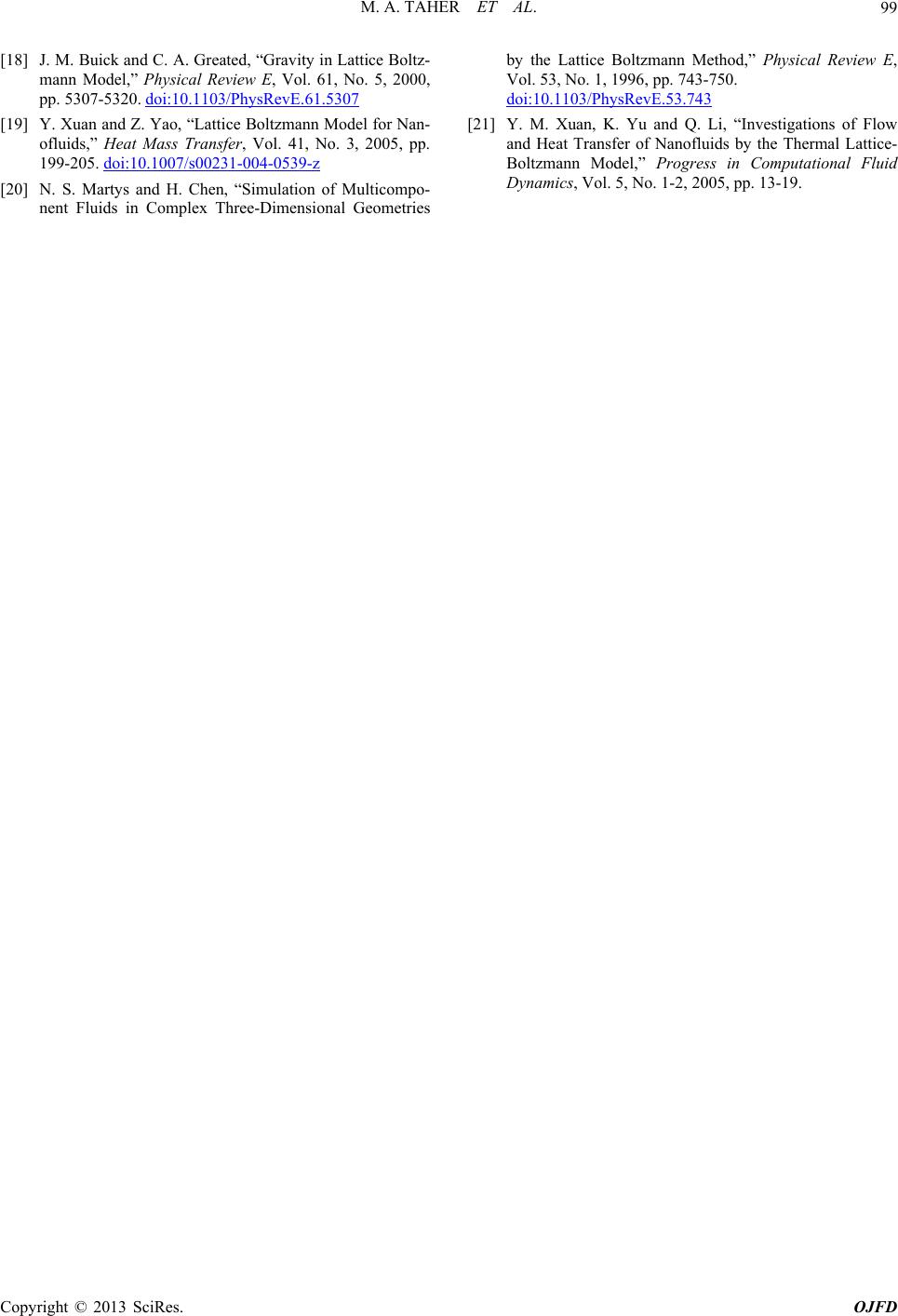 M. A. TAHER ET AL. Copyright © 2013 SciRes. OJFD 99 z- [18] J. M. Buick and C. A. Greated, “Gravity in Lattice Bolt mann Model,” Physical Review E, Vol. 61, No. 5, 2000, pp. 5307-5320. doi:10.1103/PhysRevE.61.5307 [19] Y. Xuan and Z. Yao, “Lattice Boltzmann Model for Nan- ofluids,” Heat Mass Transfer, Vol. 41, No. 3, 2005, pp. 199-205. doi:10.1007/s00231-004-0539-z ical Review E, [20] N. S. Martys and H. Chen, “Simulation of Multicompo- nent Fluids in Complex Three-Dimensional Geometries by the Lattice Boltzmann Method,” Phys Vol. 53, No. 1, 1996, pp. 743-750. doi:10.1103/PhysRevE.53.743 [21] Y. M. Xuan, K. Yu and Q. Li, “Investigations of Flow and Heat Transfer of Nanofluids by Boltzmann Model,” Progress the Thermal Lattice- in Computational Fluid Dynamics, Vol. 5, No. 1-2, 2005, pp. 13-19. |