

Paper Menu >>
Journal Menu >>
 Materials Sciences and Applications, 2013, 4, 453-457 http://dx.doi.org/10.4236/msa.2013.48055 Published Online August 2013 (http://www.scirp.org/journal/msa) Copyright © 2013 SciRes. MSA 453 Enhanced Thermal Conductivity of Carbon Nanotube Arrays by Carbonizing Impregnated Phenolic Resins Dongmei Hu1, Hongyuan Chen1, Zhenzhong Yong1, Minghai Chen1, Xiaohua Zhang1, Qingwen Li1, Zhen Fan2,3, Zhihai Fen g2,3 1Key Laboratory of Nano-Devices and Applications, Suzhou Institute of Nano-Tech and Nano-Bionics, Chinese Academy of Sci- ences, Suzhou, China; 2State Key Laboratory of Powder Metallurgy, Central South University, Changsha, China; 3National Key Laboratory of Advanced Functional Composite Materials, Aerospace Research Institute of Materials and Processing Technology, Beijing, China. Email: [email protected] Received June 8th, 2013; revised July 9th, 2013; accepted July 18th, 2013 Copyright © 2013 Dongmei Hu et al. This is an open access article distributed under the Creative Commons Attribution License, which permits unrestricted use, distribution, and reproduction in any medium, provided the original work is properly cited. ABSTRACT A carbonization method is reported to improve the thermal conductivity of carbon nanotube (CNT) arrays. After being impregnated with phenolic resins, CNT arrays were carbonized at a temperature up to 1400˚C. As a result, pyrolytic carbon was formed and connected non-neighboring CNTs. The pyrolysis improved the room temperature conductivity from below 2 W/m·K up to 11.8 and 14.6 W/m·K with carbonization at 800˚C and 1400˚C, respectively. Besides the light mass density of 1.1 g/cm3, the C/C composites demonstrated high thermal stability and a higher conductivity up to 21.4 W/m·K when working at 500˚C. Keywords: Carbon Nanotube; Phenolic Resin; Pyrolysis; Thermal Conductivity 1. Introduction Experimental and theoretical studies have shown that the thermal conductivity of a carbon nanotube (CNT) is up to several thousand W/m·K [1-4], showing great potentials in the thermal management area. Many studies have been reported on the use of dispersed CNTs as thermal con- ducting fillers in a polymer matrix, whose thermal con- ductivity can be significantly improved by 65% - 125% even at a small loading of CNTs [5-7]. However, these CNT/polymer composites still had a much lower thermal conductivity than predicted, possibly due to the interfa- cial resistances between the CNTs and matrix or between contacting tubes, modification of the phonon conduction in CNT by the matrix, formation of voids in composites, and structural defects of CNTs, as briefly reviewed by Marconnet et al. very recently [8]. Different from the random orientation of dispersed CNTs, the aligned feature of CNT arrays offers another solution to develop thermal management materials with a unidirectionally high conductivity. The thermal conduc- tivity of CNT arrays was reported to range from several to hundreds of W/m·K [9-13]. However, the as-produced CNT arrays were difficult to use due to the weak me- chanical property in the direction perpendicular to the alignment. In order to improve the mechanical and ther- mal properties or to decrease the contact resistance of a CNT array, metal filling and/or coating [14,15], polymer impregnation using silicone rubber S160 [16], polydi- methyl siloxane [17], or epoxy [8,18], covalent bonding at contact interfaces [19], and graphitization inside the array [20,21] have been designed. The purpose of this study, based on the method of polymer impregnation, is to develop C/C composite ther- mal management materials by carbonizing phenolic res- ins within multiwalled CNT arrays, and to investigate the thermal conductivities at high working temperatures. Carbonization converted the resins into pyrolytic carbon and thus adhered non-neighboring CNTs. Owing to the pathways to conduct heat between CNTs, the thermal conductivity was significantly improved. For instance, by using a carbonization temperature of 1400˚C, the thermal conductivity was up to 14.6 W/m·K, nearly quintuple that of the raw CNT arrays. The C/C composites exhib- ited a higher conductivity of 21.4 W/m·K when working at 500˚C. The composites had a low mass density (1.1 g/cm3) and were stable up to about 550˚C in air and about 1000˚C in Ar, leading to possible applications at extreme conditions. 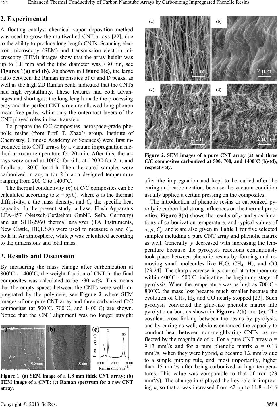 Enhanced Thermal Conductivity of Carbon Nanotube Arrays by Carbonizing Impregnated Phenolic Resins Copyright © 2013 SciRes. MSA 454 2. Experimental A floating catalyst chemical vapor deposition method was used to grow the multiwalled CNT arrays [22], due to the ability to produce long length CNTs. Scanning elec- tron microscopy (SEM) and transmission electron mi- croscopy (TEM) images show that the array height was up to 1.8 mm and the tube diameter was >30 nm, see Figures 1(a) and (b). As shown in Figure 1(c), the large ratio between the Raman intensities of G and D peaks, as well as the high 2D Raman peak, indicated that the CNTs had high crystallinity. These features had both advan- tages and shortages; the long length made the processing easy and the perfect CNT structure allowed long phonon mean free paths, while only the outermost layers of the CNT played roles in heat transfers. To prepare the C/C composites, aerospace-grade phe- nolic resins (from Prof. T. Zhao’s group, Institute of Chemistry, Chinese Academy of Sciences) were first in- troduced into CNT arrays by a vacuum impregnation me- thod at room temperature for 20 min. After this, the ar- rays were cured at 100˚C for 6 h, at 120˚C for 2 h, and finally at 180˚C for 4 h. Then the cured samples were carbonized in argon for 2 h at a designed temperature ranging from 200˚C to 1400˚C. The thermal conductivity (κ) of C/C composites can be calculated according to κ = αρCp, where α is the thermal diffusivity, ρ the mass density, and Cp the specific heat capacity. In the present study, a Laser Flash Apparatus LFA-457 (Netzsch-Gerätebau GmbH, Selb, Germany) and an STD-2960 thermal analyzer (TA Instruments, New Castle, DE,USA) were used to measure α and Cp, both in Ar atmosphere, while ρ was calculated according to the dimensions and total mass. 3. Results and Discussion By measuring the mass change after carbonization at 800˚C - 1400˚C, the weight fraction of CNT in the final composites was calculated to be ∼30 wt%. This means that the empty spaces between the CNTs were well im- pregnated by the polymers, see Figure 2 where SEM images of one pure CNT array and three carbonized C/C composites (at 500˚C, 700˚C, and 1400˚C) are shown. Notice that the CNT alignment was no longer straight Figure 1. (a) SEM image of a 1.8 mm thick CNT array; (b) TEM image of a CNT; (c) Raman spectrum for a raw CNT array. Figure 2. SEM images of a pure CNT array (a) and three C/C composites carbonized at 500, 700, and 1400˚C (b)-(d), respectively. after the impregnation and kept to be curled after the curing and carbonization, because the vacuum condition usually applied a certain pressing on the composites. The introduction of phenolic resins or carbonized py- ro lytic carbon had strong influences on the thermal prop- erties. Figure 3(a) shows the results of ρ and κ as func- tions of carbonization temperature, and typical values of α, ρ, Cp, and κ are also given in Table 1 for five selected samples including a pure CNT array and phenolic matrix as well. Generally, ρ decreased with increasing the tem- perature because the pyrolysis reactions continuously took place between phenolic resins by forming and re- moving small molecules like H2O, CH4, H2, and CO [23,24]. The sharp decrease in ρ started at a temperature within 400˚C - 500˚C, indicating the beginning stage of pyrolysis. When the temperature was as high as 700˚C - 800˚C, the mass loss became much smaller because the evolution of CH4, H2, and CO nearly stopped [23]. Such pyrolysis converted the glue-like phenolic matrix into pyrolytic carbon, as shown in Figures 2(b) and (c). The covalent cross-linking between the resins by pyrolysis, and by curing as well, obvious enhanced the capacity to conduct heat between non-neighboring CNTs, as re- flected by the magnitude of α. For a pure CNT array α = 9.13 mm2/s and for a pure phenolic matrix α = 0.16 mm2/s. When they were hybrid, α became 1.2 mm2/s due to a simple mixing rule, and, most importantly, higher than 15 mm2/s after being carbonized at high tempera- tures. This value was comparable to that of iron (23 mm2/s). The change in α played the key role in improv- ing κ, so that κ was increased from <2 up to 11.8 - 14.6 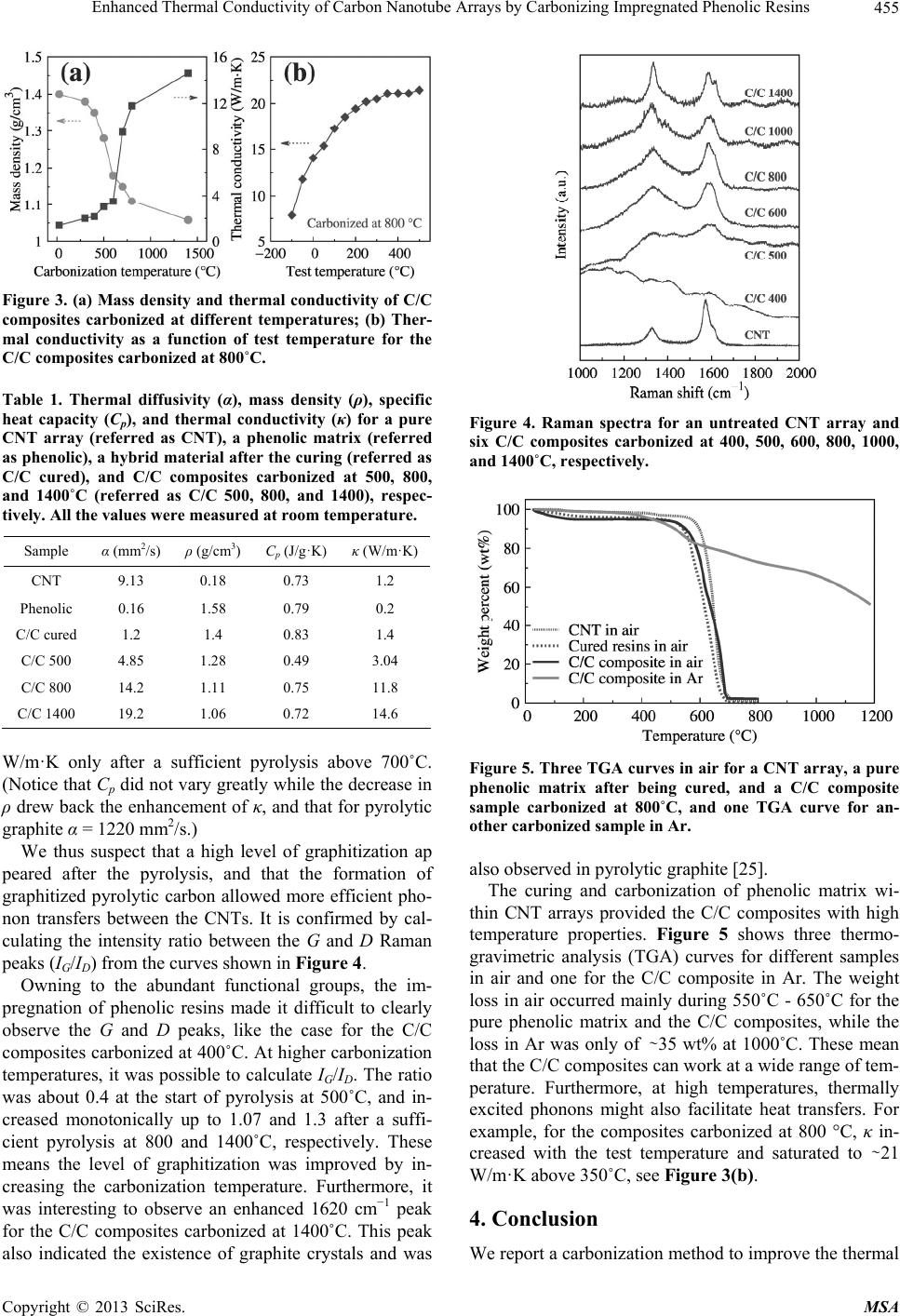 Enhanced Thermal Conductivity of Carbon Nanotube Arrays by Carbonizing Impregnated Phenolic Resins Copyright © 2013 SciRes. MSA 455 Figure 3. (a) Mass density and thermal conductivity of C/C composites carbonized at different temperatures; (b) Ther- mal conductivity as a function of test temperature for the C/C composites carbonized at 800˚C. Table 1. Thermal diffusivity (α), mass density (ρ), specific heat capacity (Cp), and thermal conductivity (κ) for a pure CNT array (referred as CNT), a phenolic matrix (referred as phenolic), a hybrid material after the curing (referred as C/C cured), and C/C composites carbonized at 500, 800, and 1400˚C (referred as C/C 500, 800, and 1400), respec- tively. All the values were measured at room temperature. Sample α (mm2/s) ρ (g/cm3) Cp (J/g·K) κ (W/m·K) CNT 9.13 0.18 0.73 1.2 Phenolic 0.16 1.58 0.79 0.2 C/C cured 1.2 1.4 0.83 1.4 C/C 500 4.85 1.28 0.49 3.04 C/C 800 14.2 1.11 0.75 11.8 C/C 1400 19.2 1.06 0.72 14.6 W/m·K only after a sufficient pyrolysis above 700˚C. (Notice that Cp did not vary greatly while the decrease in ρ drew back the enhancement of κ, and that for pyrolytic graphite α = 1220 mm2/s.) We thus suspect that a high level of graphitization ap peared after the pyrolysis, and that the formation of graphitized pyrolytic carbon allowed more efficient pho- non transfers between the CNTs. It is confirmed by cal- culating the intensity ratio between the G and D Raman peaks (IG/ID) from the curves shown in Figure 4. Owning to the abundant functional groups, the im- pregnation of phenolic resins made it difficult to clearly observe the G and D peaks, like the case for the C/C composites carbonized at 400˚C. At higher carbonization temperatures, it was possible to calculate IG/ID. The ratio was about 0.4 at the start of pyrolysis at 500˚C, and in- creased monotonically up to 1.07 and 1.3 after a suffi- cient pyrolysis at 800 and 1400˚C, respectively. These means the level of graphitization was improved by in- creasing the carbonization temperature. Furthermore, it was interesting to observe an enhanced 1620 cm−1 peak for the C/C composites carbonized at 1400˚C. This peak also indicated the existence of graphite crystals and was Figure 4. Raman spectra for an untreated CNT array and six C/C composites carbonized at 400, 500, 600, 800, 1000, and 1400˚C, respectively. Figure 5. Three TGA curves in air for a CNT array, a pure phenolic matrix after being cured, and a C/C composite sample carbonized at 800˚C, and one TGA curve for an- other carbonized sample in Ar. also observed in pyrolytic graphite [25]. The curing and carbonization of phenolic matrix wi- thin CNT arrays provided the C/C composites with high temperature properties. Figure 5 shows three thermo- gravimetric analysis (TGA) curves for different samples in air and one for the C/C composite in Ar. The weight loss in air occurred mainly during 550˚C - 650˚C for the pure phenolic matrix and the C/C composites, while the loss in Ar was only of ∼35 wt% at 1000˚C. These mean that the C/C composites can work at a wide range of tem- perature. Furthermore, at high temperatures, thermally excited phonons might also facilitate heat transfers. For example, for the composites carbonized at 800 °C, κ in- creased with the test temperature and saturated to ∼21 W/m·K above 350˚C, see Figure 3(b). 4. Conclusion We report a carbonization method to improve the thermal  Enhanced Thermal Conductivity of Carbon Nanotube Arrays by Carbonizing Impregnated Phenolic Resins Copyright © 2013 SciRes. MSA 456 conductivity of CNT arrays. Carbonization converted phenolic matrix into pyrolytic carbon to form C/C com- posites, and enhanced heat transfers between non-neigh- boring CNTs. The thermal conductivity of <2 W/m·K for a pure CNT array was significantly improved to 11.8 and 14.6 W/m·K with carbonization at 800˚C and 1400˚C, respectively. The C/C composites showed high thermal stability up to ~550˚C in air and up to ~1000˚C in Ar. When working at 500˚C in Ar, the thermal conductivity was up to 21.4 W/m·K. 5. Acknowledgements This work is supported by the National Natural Science Foundation of China (21273269), National Basic Re- search Program (2010CB934700) by the Ministry of Science and Technology, and International Science & Technology Cooperation Project (BZ2011049) of Jiangsu Province. REFERENCES [1] S. Berber, Y.-K. Kwon and D. Tománek, “Unusually High Thermal Conductivity of Carbon Nanotubes,” Phy- sical Review Letters, Vol. 84, No. 20, 2000, pp. 4613- 4616. doi:10.1103/PhysRevLett.84.4613 [2] P. Kim, L. Shi, A. Majumdar and P. L. McEuen, “Ther- mal Transport Measurements of Individual Multiwalled Nanotubes,” Physical Review Letters, Vol. 87, No. 21, 2001, Article ID: 215502. doi:10.1103/PhysRevLett.87.215502 [3] M. Fujii, X. Zhang, H. Xie, H. Ago, K. Takahashi, T. Ikuta, H. Abe and T. Shimizu, “Measuring the Thermal Conductivity of a Single Carbon Nanotube,” Physical Re- view Letters, Vol. 95, No. 6, 2005, Article ID: 065502. doi:10.1103/PhysRevLett.95.065502 [4] E. Pop, D. Mann, Q. Wang, K. Goodson and H. Dai, “Thermal Conductance of an Individual Single-Wall Car- bon Nanotube above Room Temperature,” Nano Letters, Vol. 6, No. 1, 2006, pp. 96-100. doi:10.1021/nl052145f [5] M. J. Biercuk, M. C. Llaguno, M. Radosavljevic, J. K. Hyun, A. T. Johnson and J. E. Fischer, “Carbon Nanotube Composites for Thermal Management,” Applied Physics Letters, Vol. 80, No. 15, 2002, pp. 2767-2769. doi:10.1063/1.1469696 [6] C. H. Liu, H. Huang, Y. Wu and S. S. Fan, “Thermal Conductivity Improvement of Silicone Elastomer with Carbon Nanotube Loading,” Applied Physics Letters, Vol. 84, No. 21, 2004, pp. 4248-4250. doi:10.1063/1.1756680 [7] T. Morishita, M. Matsushita, Y. Katagiri and K. Fuku- mori, “A Novel Morphological Model for Carbon Nano- tube/Polymer Composites Having High Thermal Conduc- tivity and Electrical Insulation,” Journal of Materials Chemistry, Vol. 21, No. 15, 2011, pp. 5610-5614. doi:10.1039/c0jm04007j [8] A. M. Marconnet, N. Yamamoto, M. A. Panzer, B. L. Wardle and K. E. Goodson, “Thermal Conduction in Aligned Carbon Nanotube-Polymer Nanocomposites with High Packing Density,” ACS Nano, Vol. 5, No. 6, 2011, pp. 4818-4825. doi:10.1021/nn200847u [9] D. J. Yang, Q. Zhang, G. Chen, S. F. Yoon, J. Ahn, S. G. Wang, Q. Zhou, Q. Wang and J. Q. Li, “Thermal Con- ductivity of Multiwalled Carbon Nanotubes,” Physical Review B, Vol. 66, No. 16, 2002, Article ID: 165440. doi:10.1103/PhysRevB.66.165440 [10] X. J. Hu, A. A. Padilla, J. Xu, T. S. Fisher and K. E. Goodson, “3-Omega Measurements of Vertically Oriented Carbon Nanotubes on Silicon,” Journal of Heat Transfer, Vol. 128, No. 11, 2006, pp. 1109-1113. doi:10.1115/1.2352778 [11] Y. Xu, Y. Zhang, E. Suhir and X. Wang, “Thermal Prop- erties of Carbon Nanotube Array Used for Integrated Circuit Cooling,” Journal of Applied Physics, Vol. 100, No. 7, 2006, Article ID: 074302. doi:10.1063/1.2337254 [12] S. Shaikh, L. Li, K. Lafdi and J. Huie, “Thermal Conduc- tivity of an Aligned Carbon Nanotube Array,” Carbon, Vol. 45, No. 13, 2007, pp. 2608-2613. doi:10.1016/j.carbon.2007.08.011 [13] M. B. Jakubinek, M. Anne White, G. Li, C. Jayasinghe, W. Cho, M. J. Schulz and V. Shanov, “Thermal and Elec- trical Conductivity of Tall, Vertically Aligned Carbon Nanotube Arrays,” Carbon, Vol. 48, No. 13, 2010, pp. 3947-3952. doi:10.1016/j.carbon.2010.06.063 [14] Q. Ngo, B. A. Cruden, A. M. Cassell, G. Sims, M. Mey- yappan, J. Li and C. Y. Yang, “Thermal Interface Proper- ties of Cu filled Vertically Aligned Carbon Nanofiber Arrays,” Nano Letters, Vol. 4, No. 12, 2004, pp. 2403- 2407. doi:10.1021/nl048506t [15] M. A. Panzer, G. Zhang, D. Mann, X. Hu, E. Pop, H. Dai and K. E. Goodson, “Thermal Properties of Metal-Coated Vertically Aligned Single-Wall Nanotube Arrays,” Jour- nal of Heat Transfer, Vol. 130, No. 5, 2008, Article ID: 052401. doi:10.1115/1.2885159 [16] H. Huang, C. Liu, Y. Wu and S. Fan, “Aligned Carbon Nanotube Composite Films for Thermal Management,” Advanced Materials, Vol. 17, No. 13, 2005, pp. 1652- 1656. doi:10.1002/adma.200500467 [17] T. Borca-Tasciuc, M. Mazumder, Y. Son, S. K. Pal, L. S. Schadler and P. M. Ajayan, “Anisotropic Thermal Diffu- sivity Characterization of Aligned Carbon Nanotube- Polymer Composites,” Journal of Nanoscience and Nano- technology, Vol. 7, No. 4-5, 2007, pp. 1581-1588. doi:10.1166/jnn.2007.657 [18] W. Lin, K.-S. Moon and C. P. Wong, “A Combined Pro- cess of in Situ Functionalization and Microwave Treat- ment to Achieve Ultrasmall Thermal Expansion of Align- ed Carbon Nanotube-Polymer Nanocomposites: Toward Applications as Thermal Interface Materials,” Advanced Materials, Vol. 21, No. 23, 2009, pp. 2421-2424. doi:10.1002/adma.200803548 [19] W. Lin, R. Zhang, K.-S. Moon and C. P. Wong, “Mo- lecular Phonon Couplers at Carbon Nanotube/Substrate Interface to Enhance Interfacial Thermal Transport,” Carbon, Vol. 48, No. 1, 2010, pp. 107-113. doi:10.1016/j.carbon.2009.08.033 [20] Q.-M. Gong, Z. Li, X.-D. Bai, D. Li, Y. Zhao and J. Li-  Enhanced Thermal Conductivity of Carbon Nanotube Arrays by Carbonizing Impregnated Phenolic Resins Copyright © 2013 SciRes. MSA 457 ang, “Thermal Properties of Aligned Carbon Nanotube/ Carbon Nanocomposites,” Materials Science and Engi- neering: A, Vol. 384, No. 1-2, 2004, pp. 209-214. doi:10.1016/j.msea.2004.06.006 [21] H. Li, C. Liu and S. Fan, “Catalyzed Filling of Carbon Nanotube Array with Graphite and the Thermal Proper- ties of the Composites,” The Journal of Physical Chemis- try C, Vol. 112, No. 15, 2008, pp. 5840-5842. doi:10.1021/jp7119697 [22] C. Singh, M. S. P. Shaffer, K. K. K. Koziol, I. A. Kinloch and A. H. Windle, “Towards the Production of Large- Scale Aligned Carbon Nanotubes,” Chemical Physics Letters, Vol. 372, No. 5-6, 2003, pp. 860-865. doi:10.1016/S0009-2614(03)00531-1 [23] K. A. Trick and T. E. Saliba, “Mechanisms of the Pyroly- sis of Phenolic Resin in a Carbon/Phenolic Composite,” Carbon, Vol. 33, No. 11, 1995, pp. 1509-1515. doi:10.1016/0008-6223(95)00092-R [24] C.-L. Liu, W.-S. Dong, J.-R. Song and L. Liu, “Evolution of Microstructure and Properties of Phenolic Fibers dur- ing Carbonization,” Materials Science and Engineering: A, Vol. 459, No. 1-2, 2007, pp. 347-354. doi:10.1016/j.msea.2007.02.067 [25] R. J. Nemanich and S. A. Solin, “First- and Second-Order Raman Scattering from Finite-Size Crystals of Graphite,” Physical Review B, Vol. 20, No. 2, 1979, pp. 392-401. doi:10.1103/PhysRevB.20.392 |