

Paper Menu >>
Journal Menu >>
 International Journal of Medical Physics, Clinical Engineering and Radiation Oncology, 2013, 2, 69-75 http://dx.doi.org/10.4236/ijmpcero.2013.23010 Published Online August 2013 (http://www.scirp.org/journal/ijmpcero) Comparison of the Motion Accuracy of a Six Degrees of Freedom Radiotherapy Couch with and without Weights Akihiro Takemura1, Shinichi Ueda2, Kimiya Noto2, Hironori Kojima2, Naoki Isomura2 1Faculty of Health Sciences, Institute of Medical, Pharmaceutical and Health Sciences, Kanazawa University, Kanazawa, Japan 2Department of Radiology, Kanazawa University Hospital, Kanazawa, Japan Email: [email protected].kanazawa-u.ac.jp Received May 17, 2013; revised June 18, 2013; accepted July 5, 2013 Copyright © 2013 Akihiro Takemura et al. This is an open access article distributed under the Creative Commons Attribution Li- cense, which permits unrestricted use, distribution, and reproduction in any medium, provided the original work is properly cited. ABSTRACT In this study, we compared the motion accuracy of six degrees of freedom (6D) couch for precision radiotherapy with or without weights attached to the couch. Two digital cameras were focused on the iso-center of a linear accelerator. Im- ages of a needle which had been fixed to the 6D couch were obtained using the cameras when the couch moved in translation and rotation around each axis. The three-dimensional (3D) coordinates of the needle were calculated from coordinate values in the images. A coordinate error of the needle position relative to the theoretical position was calcu- lated. The errors were obtained with or without a 60 kg weight attached to the 6D couch, and these errors were com- pared with each other. The mean distance of the 3D error vectors for the weighted test was 0.21 ± 0.11 mm, and ˃0.16 ± 0.09 mm for the non-weighted test (p < 0.05). However, the difference of two values was 0.06 mm which is smaller than the minimum distance the 6D couch system can move correctly. The variance of 0.16 mm for the Y coordinate errors for the weighted test only was larger than that for the non-weighted test, which was 0.06 mm (p < 0.05). We found that a total weight of 60 kg did not affect the accuracy of the 6D couch clinically. However, the variance of the Y coordinate errors was increased. This might suggest that the addition of this weight increase the uncertainty of the mo- tion of the 6D couch. Keywords: 6D Couch; IGRT; Accuracy Assessment 1. Introduction A six degrees of freedom (6D) couch with an infrared system is an effective system for the precise correction of patient setup errors in image guided radiation therapy (IGRT). To use a 6D couch for precision IGRT, accurate evaluation of the 6D couch should be performed. The accuracy and uncertainty involved in the use of a 6D couch with an infrared system were usually evaluated us- ing a linear accelerator (LINAC) integrated imaging sys- tem, such as an X-ray radiography system or cone-beam computed tomography (CBCT) system. A 6D couch combined with an ExacTrac system (BrainLAB AG, Feldkirchen, Germany) has been evaluated with regard to uncertainty in its precision in several studies [1-4]. These evaluations were undertaken using the Wiston-Lutz test or by means of image registration software for ExacTrac X-ray images and for CBCT images. However, the Wis- ton-Lutz test only evaluates the origin of the 6D couch motion. Another 6D couch, HexaPOD evo (Elekta AB, Stock- holm, Sweden) was also evaluated regarding its accuracy using its image registration software with CBCT images [5]. The degree of accuracy depended on the resolution, especially in relation to CBCT, which has a voxel size of 1 mm × 1 mm × 1 mm. However, in general the 6D couch can move or recognize a distance of 0.1 mm at minimum. Hayashi et al. reported uncertainty regarding a 6D couch system on iso-centric rotation with a section sheet and a high-resolution digital camera [6]. Addition- ally, the accuracy and uncertainty of 6D couch systems reported in previous papers were evaluated without the use of an attached weight. A 6D couch with a patient on it should move accurately; consequently the accuracy of a 6D couch with attached weights should be evaluated. In the present study, we have compared the accuracy of 6D couch motion with or without the use of an at- tached weight. 2. Materials and Methods A HexaPOD evo as a 6D couch system was evaluated for C opyright © 2013 SciRes. IJMPCERO 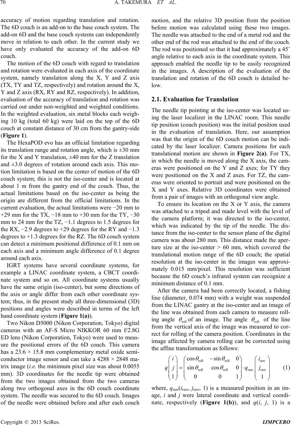 A. TAKEMURA ET AL. 70 accuracy of motion regarding translation and rotation. The 6D couch is an add-on to the base couch system. The add-on 6D and the base couch systems can independently move in relation to each other. In the current study we have only evaluated the accuracy of the add-on 6D couch. The motion of the 6D couch with regard to translation and rotation were evaluated in each axis of the coordinate system, namely translation along the X, Y and Z axis (TX, TY and TZ, respectively) and rotation around the X, Y and Z axis (RX, RY and RZ, respectively). In addition, evaluation of the accuracy of translation and rotation was carried out under non-weighted and weighted conditions. In the weighted evaluation, six metal blocks each weigh- ing 10 kg (total 60 kg) were laid on the top of the 6D couch at constant distance of 30 cm from the gantry-side (Figure 1). The HexaPOD evo has an official limitation regarding its translation range and rotation angle, which is ±30 mm for the X and Y translation, ±40 mm for the Z translation and ±3.0 degrees of rotation around each axis. This mo- tion limitation is based on the center of motion of the 6D couch system; this is not the iso-center and is located at about 1 m from the gantry end of the couch. Thus, the actual limitations based on the iso-center as being the origin are different from the official limitations. In the current evaluation, the actual limitations were −20 mm to +29 mm for the TX, −18 mm to +30 mm for the TY, −30 mm to 24 mm for the TZ, −1.1 degrees to 1.5 degrees for the RX, −2.9 degrees to +29 degrees for the RY and −1.3 degrees to +1.3 degrees for the RZ. The 6D couch system can detect a minimum positional difference of 0.1 mm on each axis and a minimum angle difference of 0.1 degree around each axis. IGRT systems have several coordinate systems, for example a LINAC coordinate system, a CBCT coordi- nate system and so on. All coordinate systems usually have the same origin (iso-center), but some directions of the axis or angle differ from each other coordinate sys- tem; thus, in the present study all three-dimensional (3D) positions and angles were described in terms of the left hand coordinate system (Figure 1(a)). Two Nikon D5000 (Nikon Corporation, Tokyo) digital cameras with an AF-S Micro NIKKOR 60 mm f/2.8G ED lens (Nikon Corporation, Tokyo) were used to meas- ure the positional errors of the 6D couch. This camera has a 23.6 × 15.8 mm complementary metal oxide semi- conductor image sensor and can take a 4288 × 2848 ma- trix image (i.e. the minimum pixel size was about 0.0055 mm). 3D coordinates for the needle tip were obtained from the two images obtained from the two cameras along two orthogonal axes in the 6D couch coordinate system. The needle was secured to the 6D couch. Images of the needle were obtained before and after each couch motion, and the relative 3D position from the position before motion was calculated using these two images. The needle was attached to the end of a metal rod and the other end of the rod was attached to the end of the couch. The rod was positioned so that it had approximately a 45˚ angle relative to each axis in the coordinate system. This approach enabled the needle tip to be easily recognized in the images. A description of the evaluation of the translation and rotation of the 6D couch is detailed be- low. 2.1. Evaluation for Translation The needle tip pointing at the iso-center was located us- ing the laser localizer in the LINAC room. This needle tip position (couch position) was the initial position used in the evaluation of translation. Here, our assumption was that the origin of the 6D couch motion can be indi- cated by the laser localizer. Camera positions for each translational motion are shown in Figure 2(a). For TX, in which the needle is moved along the X axis, the cam- eras were positioned on the Y and Z axes; for TY they were positioned on the X and Z axes. For TZ, the cam- eras were oriented to portrait and were positioned on the X and Y axes. Relative 3D coordinates were obtained from a pair of images with an orthogonal view angle. To ensure its location on the X or Y axis, the camera was attached to a tripod and made level with the level of the camera platform; it was directed to the iso-center, which was indicated by the tip of the needle. The dis- tance from the iso-center to the sensor plane of the digital camera was about 280 mm. This distance made the aper- ture size at the iso-center ˃ 60 mm, which covered the translational motion range of the 6D couch; the spatial resolution at the iso-center in the images was approxi- mately 0.015 mm/pixel. This resolution was sufficient because the 6D couch’s infrared system can recognize a minimum distance of 0.1 mm. After the camera had been correctly located, a fishing line (diameter, 0.074 mm) with a weight was suspended from the LINAC gantry at the iso-center and an image of the line was obtained from each camera to measure roll- ing angle roll of an image. The angle roll of the line from the vertical axis of the image was measured to cor- rect for rolling of the camera position. Coordinates in the image affected by camera rolling can be corrected using the affine transformation as follows: roll rollraw rollrollrawraw cossin 0 sincos 0 10 011 ii qjq j (1) where, qraw(iraw, jraw, 1) is a measured position in an im- age, i and j were lateral coordinate and vertical coordi- nate, respectively (Figure 1(b)), and q(i, j, 1) is a Copyright © 2013 SciRes. IJMPCERO 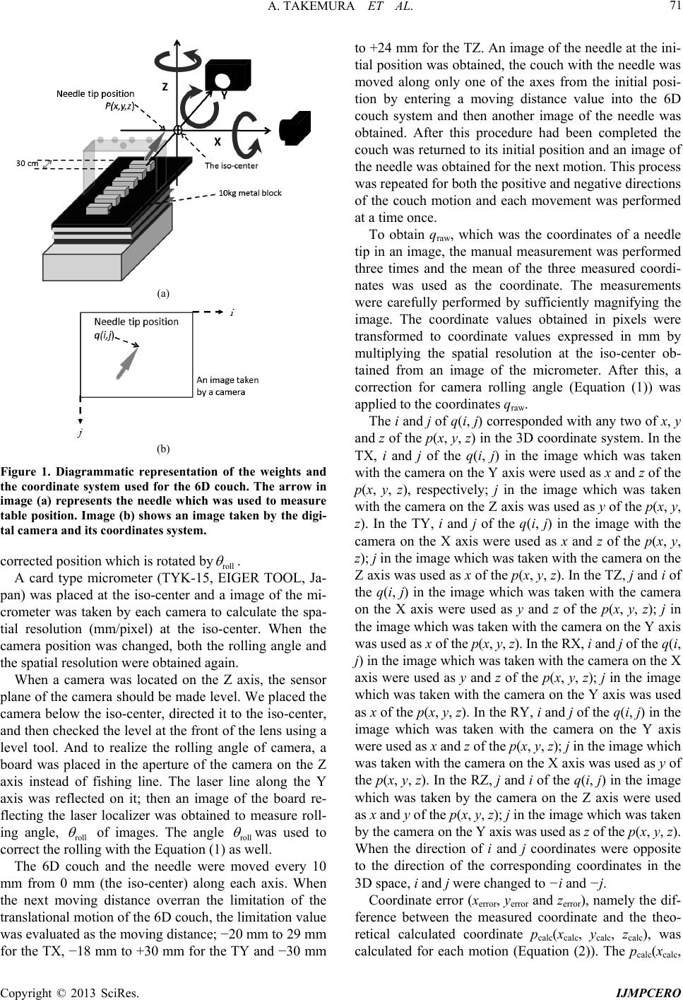 A. TAKEMURA ET AL. 71 (a) (b) Figure 1. Diagrammatic representation of the weights and the coordinate system used for the 6D couch. The arrow in image (a) represents the needle which was used to measure table position. Image (b) shows an image taken by the digi- tal camera and its coordinates system. corrected position which is rotated byroll . A card type micrometer (TYK-15, EIGER TOOL, Ja- pan) was placed at the iso-center and a image of the mi- crometer was taken by each camera to calculate the spa- tial resolution (mm/pixel) at the iso-center. When the camera position was changed, both the rolling angle and the spatial resolution were obtained again. When a camera was located on the Z axis, the sensor plane of the camera should be made level. We placed the camera below the iso-center, directed it to the iso-center, and then checked the level at the front of the lens using a level tool. And to realize the rolling angle of camera, a board was placed in the aperture of the camera on the Z axis instead of fishing line. The laser line along the Y axis was reflected on it; then an image of the board re- flecting the laser localizer was obtained to measure roll- ing angle, roll of images. The angle roll was used to correct the rolling with the Equation (1) as well. The 6D couch and the needle were moved every 10 mm from 0 mm (the iso-center) along each axis. When the next moving distance overran the limitation of the translational motion of the 6D couch, the limitation value was evaluated as the moving distance; −20 mm to 29 mm for the TX, −18 mm to +30 mm for the TY and −30 mm to +24 mm for the TZ. An image of the needle at the ini- tial position was obtained, the couch with the needle was moved along only one of the axes from the initial posi- tion by entering a moving distance value into the 6D couch system and then another image of the needle was obtained. After this procedure had been completed the couch was returned to its initial position and an image of the needle was obtained for the next motion. This process was repeated for both the positive and negative directions of the couch motion and each movement was performed at a time once. To obtain qraw, which was the coordinates of a needle tip in an image, the manual measurement was performed three times and the mean of the three measured coordi- nates was used as the coordinate. The measurements were carefully performed by sufficiently magnifying the image. The coordinate values obtained in pixels were transformed to coordinate values expressed in mm by multiplying the spatial resolution at the iso-center ob- tained from an image of the micrometer. After this, a correction for camera rolling angle (Equation (1)) was applied to the coordinates qraw. The i and j of q(i, j) corresponded with any two of x, y and z of the p(x, y, z) in the 3D coordinate system. In the TX, i and j of the q(i, j) in the image which was taken with the camera on the Y axis were used as x and z of the p(x, y, z), respectively; j in the image which was taken with the camera on the Z axis was used as y of the p(x, y, z). In the TY, i and j of the q(i, j) in the image with the camera on the X axis were used as x and z of the p(x, y, z); j in the image which was taken with the camera on the Z axis was used as x of the p(x, y, z). In the TZ, j and i of the q(i, j) in the image which was taken with the camera on the X axis were used as y and z of the p(x, y, z); j in the image which was taken with the camera on the Y axis was used as x of the p(x, y, z). In the RX, i and j of the q(i, j) in the image which was taken with the camera on the X axis were used as y and z of the p(x, y, z); j in the image which was taken with the camera on the Y axis was used as x of the p(x, y, z). In the RY, i and j of the q(i, j) in the image which was taken with the camera on the Y axis were used as x and z of the p(x, y, z); j in the image which was taken with the camera on the X axis was used as y of the p(x, y, z). In the RZ, j and i of the q(i, j) in the image which was taken by the camera on the Z axis were used as x and y of the p(x, y, z); j in the image which was taken by the camera on the Y axis was used as z of the p(x, y, z). When the direction of i and j coordinates were opposite to the direction of the corresponding coordinates in the 3D space, i and j were changed to −i and −j. Coordinate error (xerror, yerror and zerror), namely the dif- ference between the measured coordinate and the theo- retical calculated coordinate p calc(xcalc, y calc, z calc), was calculated for each motion (Equation (2)). The pcalc(xcalc, Copyright © 2013 SciRes. IJMPCERO 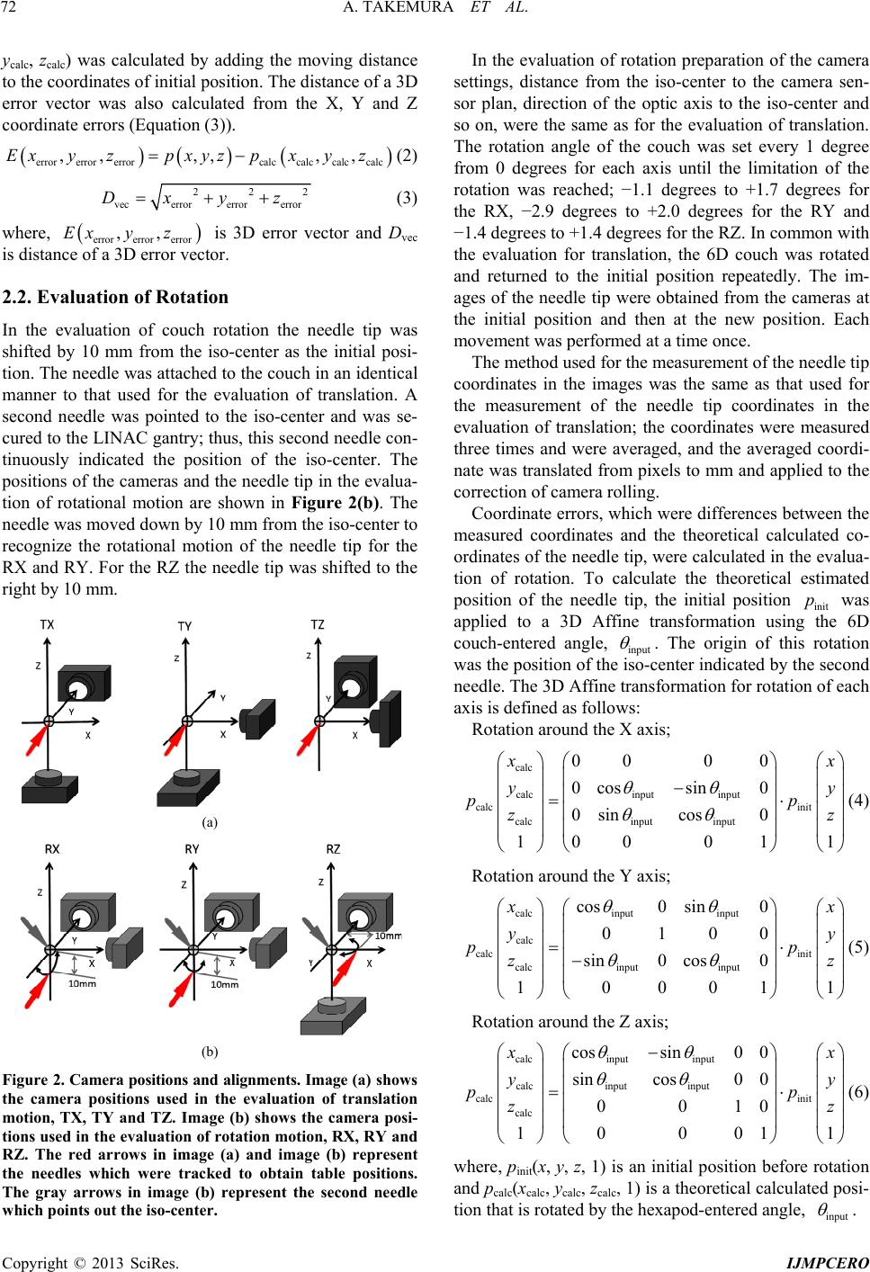 A. TAKEMURA ET AL. 72 ycalc, zcalc) was calculated by adding the moving distance to the coordinates of initial position. The distance of a 3D error vector was also calculated from the X, Y and Z coordinate errors (Equation (3)). errorerror errorcalccalccalc calc ,, ,,,,Exyzpxyz pxyz (2) 22 vecerrorerror error Dxyz 2 (3) where, is 3D error vector and Dvec is distance of a 3D error vector. errorerror error ,,Exy z 2.2. Evaluation of Rotation In the evaluation of couch rotation the needle tip was shifted by 10 mm from the iso-center as the initial posi- tion. The needle was attached to the couch in an identical manner to that used for the evaluation of translation. A second needle was pointed to the iso-center and was se- cured to the LINAC gantry; thus, this second needle con- tinuously indicated the position of the iso-center. The positions of the cameras and the needle tip in the evalua- tion of rotational motion are shown in Figure 2(b). The needle was moved down by 10 mm from the iso-center to recognize the rotational motion of the needle tip for the RX and RY. For the RZ the needle tip was shifted to the right by 10 mm. (a) (b) Fi gure 2. Camera positions and alignments. Im age (a) sho ws the camera positions used in the evaluation of translation motion, TX, TY and TZ. Image (b) shows the camera posi- tions used in the evaluation of rotation motion, RX, RY and RZ. The red arrows in image (a) and image (b) represent the needles which were tracked to obtain table positions. The gray arrows in image (b) represent the second needle which points out the iso-center. In the evaluation of rotation preparation of the camera settings, distance from the iso-center to the camera sen- sor plan, direction of the optic axis to the iso-center and so on, were the same as for the evaluation of translation. The rotation angle of the couch was set every 1 degree from 0 degrees for each axis until the limitation of the rotation was reached; −1.1 degrees to +1.7 degrees for the RX, −2.9 degrees to +2.0 degrees for the RY and −1.4 degrees to +1.4 degrees for the RZ. In common with the evaluation for translation, the 6D couch was rotated and returned to the initial position repeatedly. The im- ages of the needle tip were obtained from the cameras at the initial position and then at the new position. Each movement was performed at a time once. The method used for the measurement of the needle tip coordinates in the images was the same as that used for the measurement of the needle tip coordinates in the evaluation of translation; the coordinates were measured three times and were averaged, and the averaged coordi- nate was translated from pixels to mm and applied to the correction of camera rolling. Coordinate errors, which were differences between the measured coordinates and the theoretical calculated co- ordinates of the needle tip, were calculated in the evalua- tion of rotation. To calculate the theoretical estimated position of the needle tip, the initial position init was applied to a 3D Affine transformation using the 6D couch-entered angle, input p . The origin of this rotation was the position of the iso-center indicated by the second needle. The 3D Affine transformation for rotation of each axis is defined as follows: Rotation around the X axis; calc calcinput input calc init calcinput input 000 0 0cossin 0 0sincos 0 10001 1 x x yy pp zz 1 (4) Rotation around the Y axis; calc inputinput calc calc init calcinput input cos0 sin0 0100 sin0 cos0 10001 x x yy pp zz 1 (5) Rotation around the Z axis; calcinput input calcinput input calc init calc cossin0 0 sincos0 0 0010 10001 x x yy pp zz (6) where, pinit(x, y, z, 1) is an initial position before rotation and pcalc(xcalc, ycalc, zcalc, 1) is a theoretical calculated posi- tion that is rotated by the hexapod-entered angle, input . Copyright © 2013 SciRes. IJMPCERO 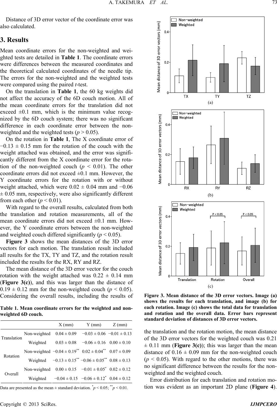 A. TAKEMURA ET AL. 73 Distance of 3D error vector of the coordinate error was also calculated. 3. Results Mean coordinate errors for the non-weighted and wei- ghted tests are detailed in Table 1. The coordinate errors were differences between the measured coordinates and the theoretical calculated coordinates of the needle tip. The errors for the non-weighted and the weighted tests were compared using the paired t-test. On the translation in Table 1, the 60 kg weights did not affect the accuracy of the 6D couch motion. All of the mean coordinate errors for the translation did not exceed ±0.1 mm, which is the minimum value recog- nized by the 6D couch system; there was no significant difference in each coordinate error between the non- weighted and the weighted tests (p > 0.05). On the rotation in Table 1, The X coordinate error of −0.13 ± 0.15 mm for the rotation of the couch with the weight attached was obtained, and the error was signifi- cantly different from the X coordinate error for the rota- tion of the non-weighted couch (p < 0.01). The other coordinate errors did not exceed ±0.1 mm. However, the Y coordinate errors for the rotation with or without weight attached, which were 0.02 ± 0.04 mm and −0.06 ± 0.05 mm, respectively, were also significantly different from each other (p < 0.01). With regard to the overall results, calculated from both the translation and rotation measurements, all of the mean coordinate errors did not exceed ±0.1 mm. How- ever, the Y coordinate errors between the non-weighted and weighted couch differed significantly (p < 0.05). Figure 3 shows the mean distances of the 3D error vectors for each motion. The translation result included all results for the TX, TY and TZ, and the rotation result included the results for the RX, RY and RZ. The mean distance of the 3D error vector for the couch rotation with the weight attached was 0.22 ± 0.14 mm (Figure 3(c)), and this was larger than the distance of 0.19 ± 0.12 mm for the non-weighted couch (p < 0.05). Considering the overall results, including the results of Table 1. Mean coordinate errors for the weighted and non- weighted 6D couch. X (mm) Y (mm) Z (mm) Non-weighted 0.04 ± 0.09 −0.03 ± 0.06 −0.01 ± 0.13 Translation Weighted 0.03 ± 0.08 −0.06 ± 0.16 0.00 ± 0.10 Non-weighted −0.04 ± 0.19** 0.02 ± 0.04** 0.07 ± 0.09 Rotation Weighted −0.13 ± 0.15** −0.06 ± 0.05** 0.08 ± 0.13 Non-weighted 0.00 ± 0.15 −0.01 ± 0.05* 0.02 ± 0.12 Overall Weighted −0.04 ± 0.15 −0.06 ± 0.12* 0.04 ± 0.12 Data are presented as the mean ± standard deviation. *p < 0.05; **p < 0.01. (a) (b) (c) Figure 3. Mean distance of the 3D error vectors. Image (a) shows the results for each translation, and image (b) for each rotation. Image (c) shows the total data for translation and rotation and the overall data. Error bars represent standard deviation of distances of 3D error vectors. the translation and the rotation motion, the mean distance of the 3D error vectors for the weighted couch was 0.21 ± 0.11 mm (Figure 3(c)); this was larger than the mean distance of 0.16 ± 0.09 mm for the non-weighted couch (p < 0.05). With regard to the other motions, there was no significant difference between the results for the non- weighted and the weighted couch. Error distribution for each translation and rotation mo- ion was evident as an important 2D plane (Figure 4). t Copyright © 2013 SciRes. IJMPCERO 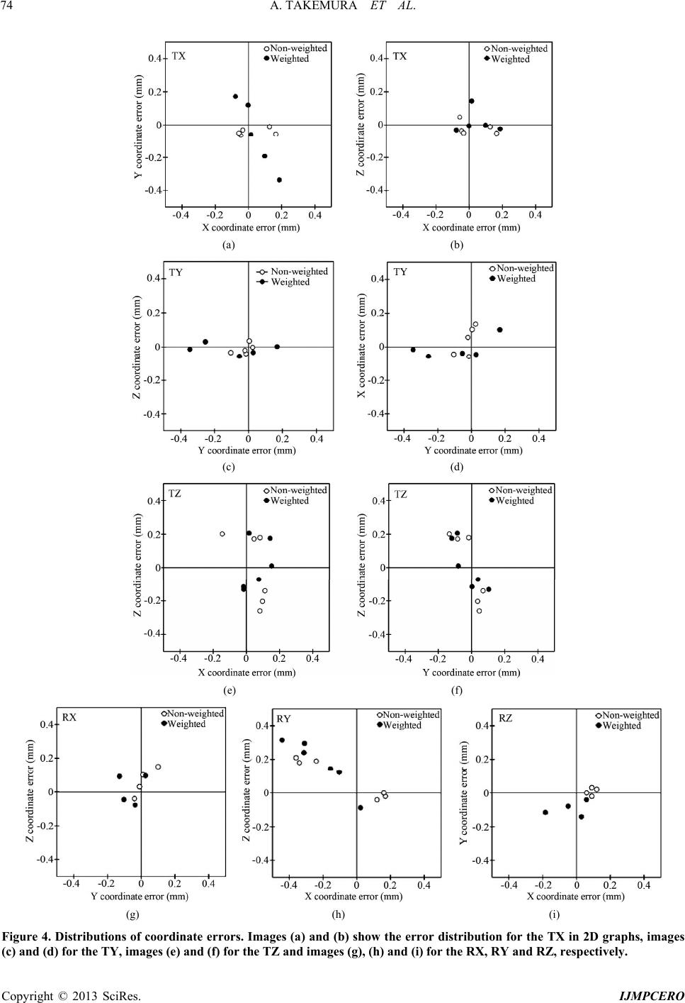 A. TAKEMURA ET AL. Copyright © 2013 SciRes. IJMPCERO 74 (a) (b) (c) (d) (e) (f) (g) (h) (i) Figure 4. Distributions of coordinate errors. Images (a) and (b) show the error distribution for the TX in 2D graphs, images c) and (d) for the TY, images (e) and (f) for the TZ and images (g), (h) and (i) for the RX, RY and RZ, respectively. ( 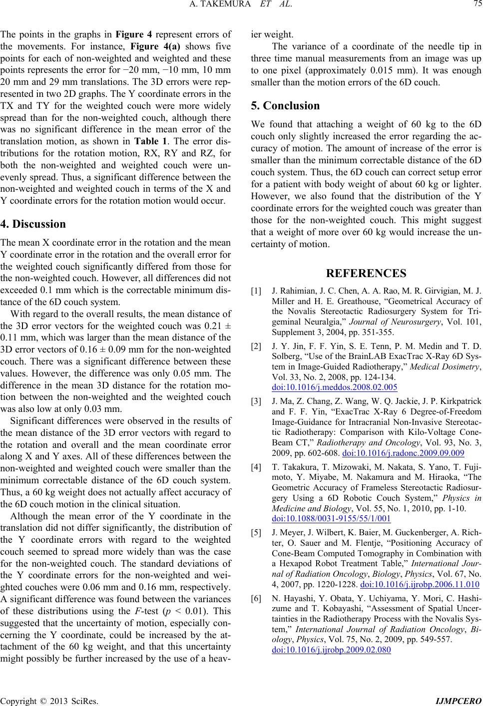 A. TAKEMURA ET AL. 75 The points in the graphs in Figure 4 represent errors of the movements. For instance, Figure 4(a) shows five points for each of non-weighted and weighted and these points represents the error for −20 mm, −10 mm, 10 mm 20 mm and 29 mm translations. The 3D errors were rep- resented in two 2D graphs. The Y coordinate errors in the TX and TY for the weighted couch were more widely spread than for the non-weighted couch, although there was no significant difference in the mean error of the translation motion, as shown in Table 1. The error dis- tributions for the rotation motion, RX, RY and RZ, for both the non-weighted and weighted couch were un- evenly spread. Thus, a significant difference between the non-weighted and weighted couch in terms of the X and Y coordinate errors for the rotation motion would occur. 4. Discussion The mean X coordinate error in the rotation and the mean Y coordinate error in the rotation and the overall error for the weighted couch significantly differed from those for the non-weighted couch. However, all differences did not exceeded 0.1 mm which is the correctable minimum dis- tance of the 6D couch system. With regard to the overall results, the mean distance of the 3D error vectors for the weighted couch was 0.21 ± 0.11 mm, which was larger than the mean distance of the 3D error vectors of 0.16 ± 0.09 mm for the non-weighted couch. There was a significant difference between these values. However, the difference was only 0.05 mm. The difference in the mean 3D distance for the rotation mo- tion between the non-weighted and the weighted couch was also low at only 0.03 mm. Significant differences were observed in the results of the mean distance of the 3D error vectors with regard to the rotation and overall and the mean coordinate error along X and Y axes. All of these differences between the non-weighted and weighted couch were smaller than the minimum correctable distance of the 6D couch system. Thus, a 60 kg weight does not actually affect accuracy of the 6D couch motion in the clinical situation. Although the mean error of the Y coordinate in the translation did not differ significantly, the distribution of the Y coordinate errors with regard to the weighted couch seemed to spread more widely than was the case for the non-weighted couch. The standard deviations of the Y coordinate errors for the non-weighted and wei- ghted couches were 0.06 mm and 0.16 mm, respectively. A significant difference was found between the variances of these distributions using the F-test (p < 0.01). This suggested that the uncertainty of motion, especially con- cerning the Y coordinate, could be increased by the at- tachment of the 60 kg weight, and that this uncertainty might possibly be further increased by the use of a heav- ier weight. The variance of a coordinate of the needle tip in three time manual measurements from an image was up to one pixel (approximately 0.015 mm). It was enough smaller than the motion errors of the 6D couch. 5. Conclusion We found that attaching a weight of 60 kg to the 6D couch only slightly increased the error regarding the ac- curacy of motion. The amount of increase of the error is smaller than the minimum correctable distance of the 6D couch system. Thus, the 6D couch can correct setup error for a patient with body weight of about 60 kg or lighter. However, we also found that the distribution of the Y coordinate errors for the weighted couch was greater than those for the non-weighted couch. This might suggest that a weight of more over 60 kg would increase the un- certainty of motion. REFERENCES [1] J. Rahimian, J. C. Chen, A. A. Rao, M. R. Girvigian, M. J. Miller and H. E. Greathouse, “Geometrical Accuracy of the Novalis Stereotactic Radiosurgery System for Tri- geminal Neuralgia,” Journal of Neurosurgery, Vol. 101, Supplement 3, 2004, pp. 351-355. [2] J. Y. Jin, F. F. Yin, S. E. Tenn, P. M. Medin and T. D. Solberg, “Use of the BrainLAB ExacTrac X-Ray 6D Sys- tem in Image-Guided Radiotherapy,” Medical Dosimetry, Vol. 33, No. 2, 2008, pp. 124-134. doi:10.1016/j.meddos.2008.02.005 [3] J. Ma, Z. Chang, Z. Wang, W. Q. Jackie, J. P. Kirkpatrick and F. F. Yin, “ExacTrac X-Ray 6 Degree-of-Freedom Image-Guidance for Intracranial Non-Invasive Stereotac- tic Radiotherapy: Comparison with Kilo-Voltage Cone- Beam CT,” Radiotherapy and Oncology, Vol. 93, No. 3, 2009, pp. 602-608. doi:10.1016/j.radonc.2009.09.009 [4] T. Takakura, T. Mizowaki, M. Nakata, S. Yano, T. Fuji- moto, Y. Miyabe, M. Nakamura and M. Hiraoka, “The Geometric Accuracy of Frameless Stereotactic Radiosur- gery Using a 6D Robotic Couch System,” Physics in Medicine and Biology, Vol. 55, No. 1, 2010, pp. 1-10. doi:10.1088/0031-9155/55/1/001 [5] J. Meyer, J. Wilbert, K. Baier, M. Guckenberger, A. Rich- ter, O. Sauer and M. Flentje, “Positioning Accuracy of Cone-Beam Computed Tomography in Combination with a Hexapod Robot Treatment Table,” International Jour- nal of Radiation Oncology, Biology, Physics, Vol. 67, No. 4, 2007, pp. 1220-1228. doi:10.1016/j.ijrobp.2006.11.010 [6] N. Hayashi, Y. Obata, Y. Uchiyama, Y. Mori, C. Hashi- zume and T. Kobayashi, “Assessment of Spatial Uncer- tainties in the Radiotherapy Process with the Novalis Sys- tem,” International Journal of Radiation Oncology, Bi- ology, Physics, Vol. 75, No. 2, 2009, pp. 549-557. doi:10.1016/j.ijrobp.2009.02.080 Copyright © 2013 SciRes. IJMPCERO |