

Paper Menu >>
Journal Menu >>
 Optics and Photonics Journal, 2013, 3, 260-264 doi:10.4236/opj.2013.32B061 Published Online June 2013 (http://www.scirp.org/journal/opj) A Comparison of Active and Passive Metamaterials from Equivalent Lumped Elements Modes Ya-Fen Ge1, Hui Huang1,2, Yong Liu1, H ou -J un Sun1, X in Lv1, Li- Mi ng Si 1* 1Beijing Key Laboratory of Millimeter Wave and Terahertz Technology, Department of Electronic Engineering, Beijing Institute of Technology, Beijing, P. R. China 2Microwave Laboratory, Division of Electronics and Information Technology, National Institute of Metrology, Beijing, P. R. China Email: *[email protected] Received 2013 ABSTRACT With ever-increasing operating frequencies and complicated artificial structures, loss effects become more and more important in applications of metamaterials. Based on circuit theory and transmission line principle, the design equations for effective electromagnetic (EM) parameters (attenuation constant α, phase constant β, characteristic impedance Z0) of general active and passive metamaterial are compared and derived from the equivalent lumped circuit parameters (R, G, LL, CL, LR, CR). To verify the design equations, theα, βand Z0 in different cases, including balanced, unbal- anced, lossless, passive and active, are shown by numerical simulations. The results show that using the active method can diminish the loss effects. Meantime, it also has influence on phase constant and real part of characteristic imped- ance. Keywords: Metamaterials; Equivalent Lumped Circuit elements Modes; Loss Compensation 1. Introduction The electromagnetic (EM) material parameters, such as propagation constant (including attenuation constant and phase constant), characteristic impedance, permittivity, permeability, refractive index, phase velocity and con- ductivity, of material always used to describe the EM response in certain frequency whenever EM wave exist in or propagation (transmit/evanescent) across media [1]. Based on transmission line theory, where EM wave propagation is considered in media the EM behaviors could be entirely represented with equivalent lumped circuit parameters, i.e., resistance, conductance, induc- tance and capacitance, which are also frequency de- pendent parameters like EM parameters of material [1]. It provided the relationship between the equivalent lumped circuit parameters and the EM material parameters. These equivalent lumped circuit parameters also serve as bridges between complicated EM field calculations and straightforward circuit analysis. Hence, EM material pa- rameters can be expressed in terms of the equivalent lumped circuit parameters. Similarly, the equivalent lumped circuit parameters can be determined by EM ma- terial parameters [1,2]. Metamaterial, which control the electromagnetic waves with their structures rather than the compositions [3-6], such as zero index materials, negative refractive index metamaterials, plamonics, have received much attention owing to their extraordinary properties not readily achiev- able in nature [7-21]. Left-handed material with negative refractive index was first investigated theoretically by Veselogo in 1968 [3], which can exhibits lots of unusual physical properties, like reversed Doppler shift, inversted Snell’s low (negative refraction) and reversed Cerenkov radiation, compared with conventional righthanded ma- terial (RHM), tremendous attention has been focused on theory and engineering applications of this novel type of artificial material [7-21]. There are two main artificial methods to realize metamaterials: first, based on the resonant-type structures; second, using quasi-lumped elements developed on transmission lines. With the first method, Shelby et al. constructed the first LHM with periodical array of copper split-ring resonators (SRRs) and thin copper wires in the microwave regime [4]. By using the second method which usually termed compos- ite right/left-handed transmission line (CRLH-TL) method and utilizes transmission line (TL) principle [15-17], the EM behavior can be easily controlled by equivalent lumped circuit parameters. It is not easy to acquire purely LHM with the second method since unavoidable RH parasitic effects in nature, but the CRLH-TLs may have *Corresponding author. Copyright © 2013 SciRes. OPJ 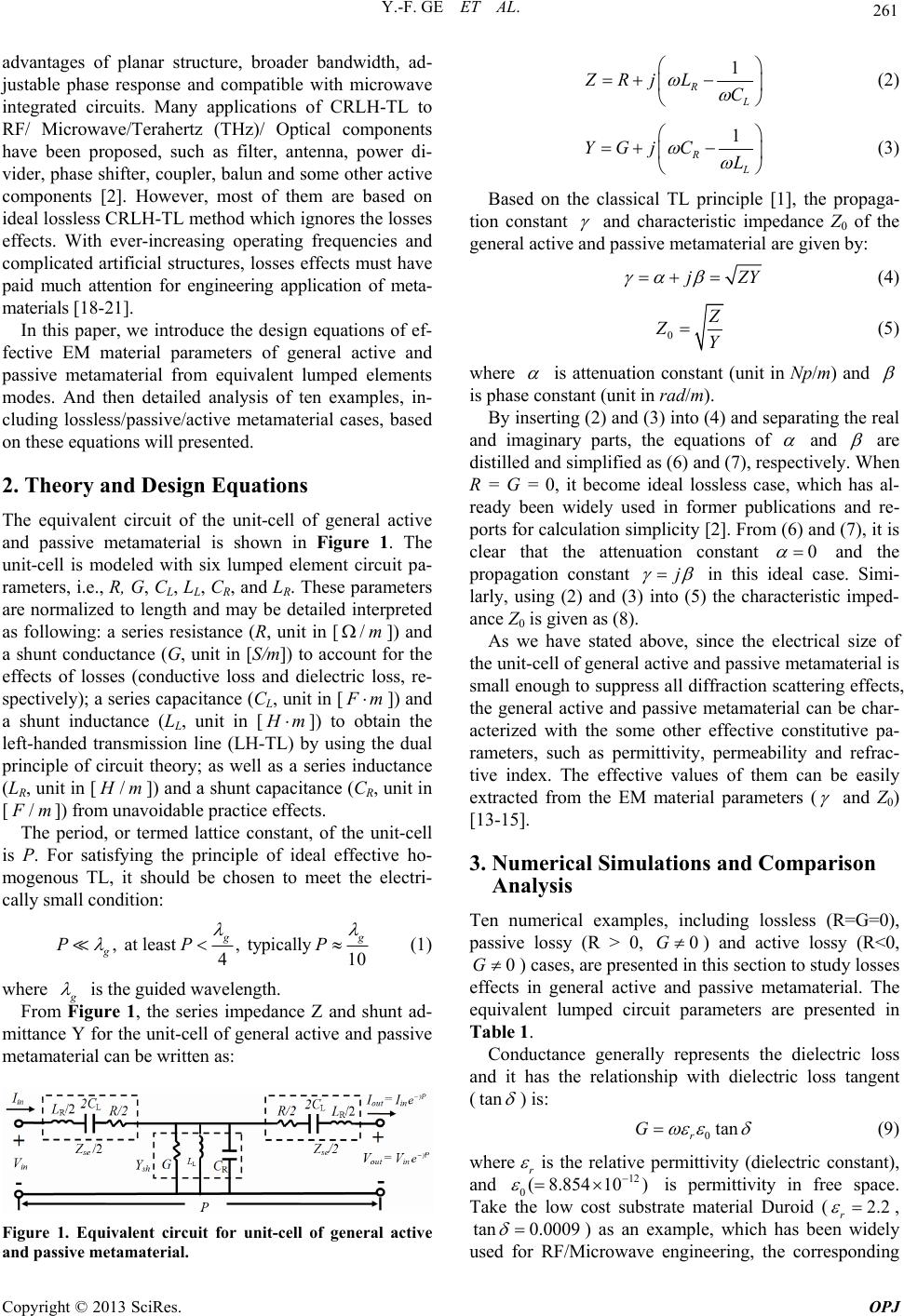 Y.-F. GE ET AL. 261 advantages of planar structure, broader bandwidth, ad- justable phase response and compatible with microwave integrated circuits. Many applications of CRLH-TL to RF/ Microwave/Terahertz (THz)/ Optical components have been proposed, such as filter, antenna, power di- vider, phase shifter, coupler, balun and some other active components [2]. However, most of them are based on ideal lossless CRLH-TL method which ignores the losses effects. With ever-increasing operating frequencies and complicated artificial structures, losses effects must have paid much attention for engineering application of meta- materials [18-21]. In this paper, we introduce the design equations of ef- fective EM material parameters of general active and passive metamaterial from equivalent lumped elements modes. And then detailed analysis of ten examples, in- cluding lossless/passive/active metamaterial cases, based on these equations will presented. 2. Theory and Design Equations The equivalent circuit of the unit-cell of general active and passive metamaterial is shown in Figure 1. The unit-cell is modeled with six lumped element circuit pa- rameters, i.e., R, G, CL, LL, CR, and LR. These parameters are normalized to length and may be detailed interpreted as following: a series resistance (R, unit in []) and a shunt conductance (G, unit in [S/m]) to account for the effects of losses (conductive loss and dielectric loss, re- spectively); a series capacitance (CL, unit in [ /m F m ]) and a shunt inductance (LL, unit in [ H m]) to obtain the left-handed transmission line (LH-TL) by using the dual principle of circuit theory; as well as a series inductance (LR, unit in [/ H m]) and a shunt capacitance (CR, unit in [/ F m]) from unavoidable practice effects. The period, or termed lattice constant, of the unit-cell is P. For satisfying the principle of ideal effective ho- mogenous TL, it should be chosen to meet the electri- cally small condition: , at least , typically 410 g g g PP P (1) where g is the guided wavelength. From Figure 1, the series impedance Z and shunt ad- mittance Y for the unit-cell of general active and passive metamaterial can be written as: Figure 1. Equivalent circuit for unit-cell of general active and passive metamaterial. 1 RL ZRjLC (2) 1 RL YGj CL (3) Based on the classical TL principle [1], the propaga- tion constant and characteristic impedance Z0 of the general active and passive metamaterial are given by: jZ Y (4) 0 Z ZY (5) where is attenuation constant (unit in Np/m) and is phase constant (unit in rad/m). By inserting (2) and (3) into (4) and separating the real and imaginary parts, the equations of and are distilled and simplified as (6) and (7), respectively. When R = G = 0, it become ideal lossless case, which has al- ready been widely used in former publications and re- ports for calculation simplicity [2]. From (6) and (7), it is clear that the attenuation constant 0 and the propagation constant j in this ideal case. Simi- larly, using (2) and (3) into (5) the characteristic imped- ance Z0 is given as (8). As we have stated above, since the electrical size of the unit-cell of general active and passive metamaterial is small enough to suppress all diffraction scattering effects, the general active and passive metamaterial can be char- acterized with the some other effective constitutive pa- rameters, such as permittivity, permeability and refrac- tive index. The effective values of them can be easily extracted from the EM material parameters ( and Z0) [13-15]. 3. Numerical Simulations and Comparison Analysis Ten numerical examples, including lossless (R=G=0), passive lossy (R > 0, 0G ) and active lossy (R<0, 0G ) cases, are presented in this section to study losses effects in general active and passive metamaterial. The equivalent lumped circuit parameters are presented in Table 1. Conductance generally represents the dielectric loss and it has the relationship with dielectric loss tangent (tan ) is: 0tan r G (9) where r is the relative permittivity (dielectric constant), and is permittivity in free space. Take the low cost substrate material Duroid ( 12 8.85410) 0( 2.2 r , tan 0.0009 ) as an example, which has been widely used for RF/Microwave engineering, the corresponding Copyright © 2013 SciRes. OPJ 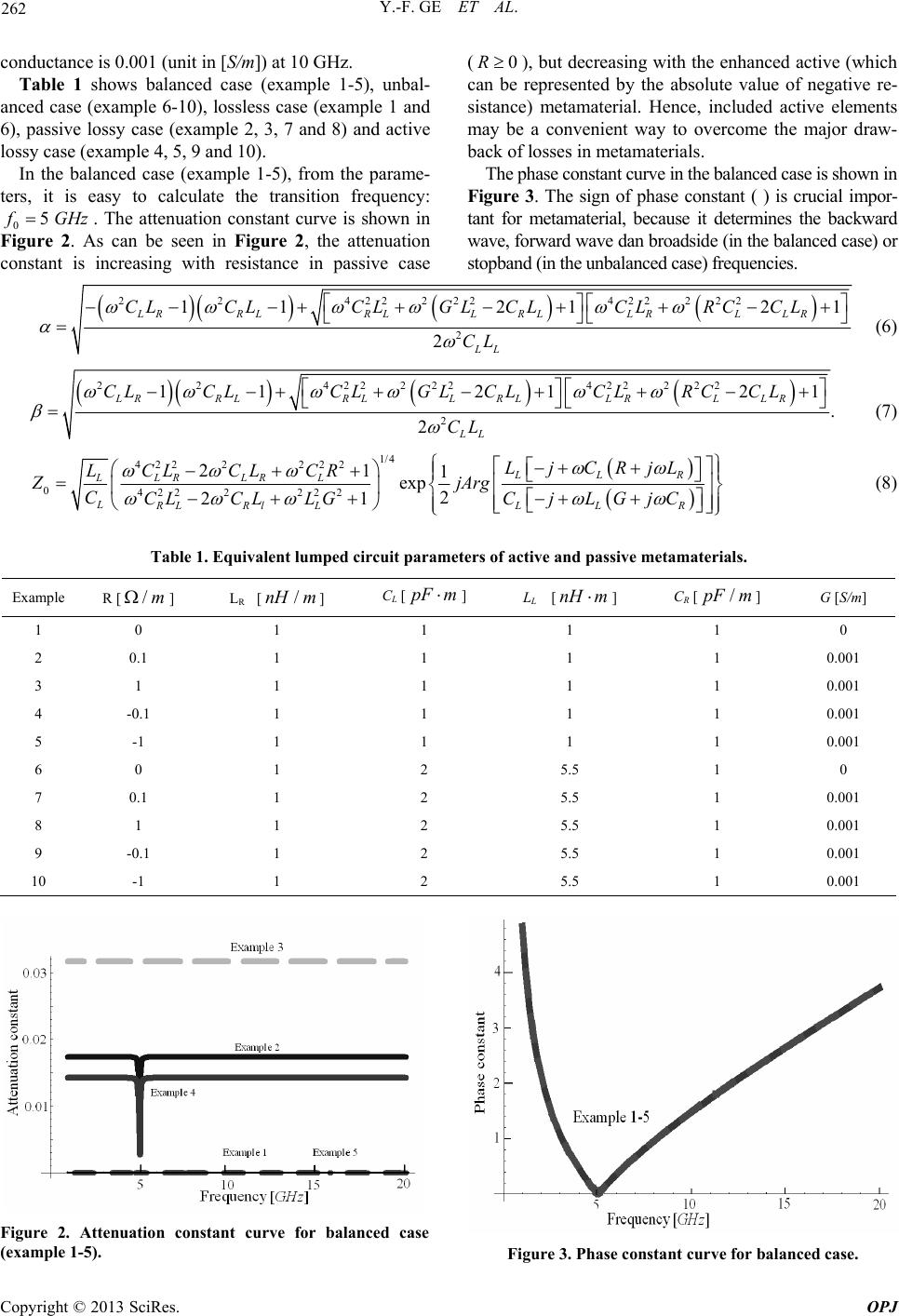 Y.-F. GE ET AL. Copyright © 2013 SciRes. OPJ 262 conductance is 0.001 (unit in [S/m]) at 10 GHz. Table 1 shows balanced case (example 1-5), unbal- anced case (example 6-10), lossless case (example 1 and 6), passive lossy case (example 2, 3, 7 and 8) and active lossy case (example 4, 5, 9 and 10). In the balanced case (example 1-5), from the parame- ters, it is easy to calculate the transition frequency: 05 f GHz. The attenuation constant curve is shown in Figure 2. As can be seen in Figure 2, the attenuation constant is increasing with resistance in passive case (), but decreasing with the enhanced active (which can be represented by the absolute value of negative re- sistance) metamaterial. Hence, included active elements may be a convenient way to overcome the major draw- back of losses in metamaterials. 0R The phase constant curve in the balanced case is shown in Figure 3. The sign of phase constant ( ) is crucial impor- tant for metamaterial, because it determines the backward wave, forward wave dan broadside (in the balanced case) or stopband (in the unbalanced case) frequencies. 224222224222 22 2 1121 2 2 LRRLRLL RLLRL LR LL CLCLCLGL CLCLRCCL CL 1 (6) 224222224222 22 2 1 12121 . 2 LRRLRLL RLLRL LR LL CLCLCLGL CLCLRC CL CL (7) 1/4 422 2222 0422222 2 21 1 exp 2 21 LLR LLR LRL LRLRl LLL R LjCRjL LCL CLCR ZjArg CCLCL LGCjLGjC (8) Table 1. Equivalent lumped circuit parameters of active and passive metamaterials. Example R [] /mLR [] /nH mCL [pF m ] LL [nH m ] CR [] /pF mG [S/m] 1 0 1 1 1 1 0 2 0.1 1 1 1 1 0.001 3 1 1 1 1 1 0.001 4 -0.1 1 1 1 1 0.001 5 -1 1 1 1 1 0.001 6 0 1 2 5.5 1 0 7 0.1 1 2 5.5 1 0.001 8 1 1 2 5.5 1 0.001 9 -0.1 1 2 5.5 1 0.001 10 -1 1 2 5.5 1 0.001 Figure 2. Attenuation constant curve for balanced case (example 1-5). Figure 3. Phase constant curve for balanced case. 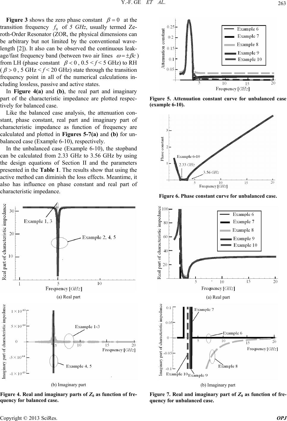 Y.-F. GE ET AL. 263 Figure 3 shows the zero phase constant 0 at the transition frequency 0 f of 5 GHz, usually termed Ze- roth-Order Resonator (ZOR, the physical dimensions can be arbitrary but not limited by the conventional wave- length [2]). It also can be observed the continuous leak- age/fast frequency band (between two air lines c ) from LH (phase constant 0 , 0.5 < f < 5 GHz) to RH (0 , 5 GHz < f < 20 GHz) state through the transition frequency point in all of the numerical calculations in- cluding lossless, passive and active states. In Figure 4(a) and (b), the real part and imaginary part of the characteristic impedance are plotted respec- tively for balanced case. Like the balanced case analysis, the attenuation con- stant, phase constant, real part and imaginary part of characteristic impedance as function of frequency are calculated and plotted in Figures 5-7(a) and (b) for un- balanced case (Example 6-10), respectively. In the unbalanced case (Example 6-10), the stopband can be calculated from 2.33 GHz to 3.56 GHz by using the design equations of Section II and the parameters presented in the Table 1 . The results show that using the active method can diminish the loss effects. Meantime, it also has influence on phase constant and real part of characteristic impedance. (a) Real part (b) Imaginary part Figure 4. Real and imaginary parts of Z0 as function of fre- quency for balanc e d case. Figure 5. Attenuation constant curve for unbalanced case (example 6-10). Figure 6. Phase constant curv e for unbalance d case . (a) Real part (b) Imaginary part Figure 7. Real and imaginary part of Z0 as function of fre- quency for unbalanc e d case. Copyright © 2013 SciRes. OPJ  Y.-F. GE ET AL. Copyright © 2013 SciRes. OPJ 264 4. Conclusions [9] L. M. Si and X. Lv, “CPW-Fed Multi-Band Omni-Directional Planar Microstrip Antenna Using Com- posite Metamaterial Resonators for Wireless Communi- cations,” Progress in Electromagnetics Research, Vol. 83, 2008, pp. 133-146. doi:10.2528/PI ER08050404 The EM material parameters equations for general active and passive metamaterial are calculated and compared from equivalent lumped elements modes. In the com- parison analysis of balanced and unbalanced lossless (R = G = 0), passive lossy (R > 0, ) and active lossy (R < 0, ) cases, different losses effects (from the changes of resistance in this paper) have some effects on phase constant and the real part of characteristic imped- ance, as well as a big influence on attenuation constant and the imaginary part of characteristic impedance. One can use included active element to metamaterial to im- prove the attenuation characteristics and then to over- come the major drawback of losses effects in metamate- rials. 0G 0G [10] L. M. Si, W. Zhu and X. Lv, “Determination of the Ef- fective Constitutive Parameters of Active Transmission Line Metamaterials,” 2012 International Workshop on Metamaterials, Nanjing, pp. 1-4, 2012. doi:10.1109/META.20 12.6464919 [11] L. M. Si, H. J. Sun, Y. Yuan, and X. Lv, “CPW-fed Compact Planar UWB Antenna with Circular Disc and Spiral Split Ring Resonators,” Progess in Electromag- netics Research Symposium, 2009, pp. 502-505. [12] L. M. Si, H. J. Sun and X. Lv, “Numerical Simulations of Backward-to-Forward Leaky-Wave Antenna with Com- posite Right/Left-Handed Coplanar Waveguide,” Chinese Physics Letters, Vol. 27, 2010. doi:10.1088 /0256-307X /27/3/034106 5. Acknowledgements [13] L. M. Si and X. Lv, “Terahertz Waves Hairpin Microstrip Band-Pass Filter and Its Application to Overlaid Dielec- tric Material Detection,” Modern Physics Letters B, Vol. 22, pp. 2843-2848, 2008. doi:10.1142 /S02179849080 17412 This work has been supported by the National High Technology Research and Development Program of China (Grant No. 2012AA8123012), the Basic Research Foundation of Beijing Institute of Technology (Grant No. 20120542015), and the National Natural Science Foun- dation of China (Grant No. 61275107). [14] Y . Liu, L. M. Si, M. Wei, P. Yan, P. Yang, H. Lu, C. Zheng, Y. Yuan, J. Mou, X. Lv and H. Sun, “Some Re- cent Developments of Microstrip Antenna,” International Journal of Antennas and Propagation, Vol. 2012, 2012. doi:10.1155 /2012/428284 [15] A. K. Iyer and G. V. Eleftheriades, “Negative Refractive Index Metamaterials Supporting 2-D Waves,” 2002 IEEE MTT-S International Microwave Symposium Digest, Vol. 2, 2002, pp. 1067-1070. doi:10.1109/MWSYM.200 2.1011823 REFERENCES [1] D. M. Pozar, Microwave Engineering, New York: Wiley, 1998. [2] C. Caloz and T. Itoh, “Electromagnetic Metamaterials: Transmission Line Theory and Microwave Applications,” New York: J. Wiley & IEEE, 2006. [16] A. A. Oliner, “A Planar Negative-Refractive-Index Me- dium without Resonant Element,” IEEE MTT-S Interna- tional Microwave Symposium Digest, Vol. 1, 2002, pp. 191-194.doi:10.1109/MW SYM.2003.1210913 [3] V. G. Veselogo, “The Electrodynamics of Substances with Simultaneously Negative Values of ε and μ,” Soviet Physics Uspekhi, Vol. 10, No. 4, 1968, pp. 509-514. doi:10.1070 /PU1968v010n 04ABEH0 03699 [17] C. Caloz and T. Itoh, “Novel Microwave Devices and Structures Based on the Transmission Line Approach of Meta-materials,” IEEE MTT-S International Microwave Symposium Digest, Vol. 1, 2003, pp. 195-198. doi:10.1109/MWSYM.200 3.1210914 [4] R. A. Shelby, D. R. Smith and S. Schultz, “Experimental Verification of A Negative Index of Refraction,” Science, Vol. 292, 2001, pp. 77-79. doi:10.1126/scien ce.1058847 [18] L. M. Si, H. J. Sun and X. Lv, “Theoretical Investigation of Terahertz Amplifier by Carbon Nanotubes within Transmission Line Metamaterials,” Microwave and Op- tical Technology Letters, Vol. 53, 2011, pp. 815-818. doi:10.1002 /mop.25870 [5] W. Zhu, I. D. Rukhlenko, L. M. Si and M. Premaratne, “Graphene-Enabled Tenability of Optical Fishnet Meta- materials,” Applied Physics Letters, Vol. 102, 2013, pp. 121911. doi:10.1063/1.4799281 [19] L. M. Si, J. X. Hou, Y. Liu and X. Lv, “Retrieve the Ef- fective Constitutive Parameters of Active Terahertz Metamaterial with Negative Differential Resistance Car- bon Nanotubes,” Acta Physica Sinica, Vol. 62, No. 3, pp, 037806, 2013. doi: 10.7498/aps.62.037806 [6] Y. Liu, L. M. Si, S. H. Zhu and H. Xin, “Experimental Realization of Integrated THz Electromagnetic Crystals (EMXT) H-Plane Horn Antenna,” Electronics Letters, Vol. 47, pp. 80–82, Jan. 2011. doi:10.1049 /el.2010.3493 [20] L. M. Si, T. Jiang, K. Chang, T. C. Chen, X. Lv, L. Ran, and H. Xin, “Active Microwave Metamaterials Incorpo- rating Ideal Gain Devices,” Materials, Vol. 4, 2011, pp. 73-83. doi:10.3390/ma4010073 [7] L. M. Si, Y. Liu, H. Sun, X. Lv and W. Zhu, “Experi- mental Relization of High Transmittance THz 90o-Bend Waveguide Using EMXT Structure,” IEEE Photonics Technology Letters, Vol. 25, No. 5, 2013, pp. 519-522. doi:10.1109 /LPT.2013.22448 78 [21] L. M. Si, W. Zhu and H. Sun, “A Compact, Planar, and CPW-Fed Metamaterial-Inspired Dual-Band Antenna,” IEEE Antennas and Wireless Propaga- tion Letters, Vol. 12, 2013, pp. 305-308. doi:10.1109 /LAWP.2013.2 249037 [8] L. M. Si, Y. Yuan, H. J. Sun and X. Lv, “Characterization and Application of Planar Terahertz Narrow Bandpass Filter with Metamaterial Resonators,” 2008 International Workshop on Metamaterials, Nanjing, pp. 351-354, 2008, pp. 9-12. doi:10.1109/META .2008.47236 12 |