

Paper Menu >>
Journal Menu >>
 Optics and Photonics Journal, 2013, 3, 232-235 doi:10.4236/opj.2013.32B054 Published Online June 2013 (http://www.scirp.org/journal/opj) Recognition of Bragg Wavelength Disturbed by Time Delay of Fiber Length in Prepositive Tunable Filter Chuan Li, Xiaoyong Chao, Yingna Li, Tao Xie, Zhengang Zhao, Xin Xiong Faculty of Information Engineering and Automation, Kunming University of Science and Technology, Kunming City, China Email: [email protected] Received 2013 ABSTRACT The wavelength shift in fiber Bragg grating does not depend directly on the total light levels, losses in the connecting fibers and couplers, or source power. However, if the tunable Fabry-Perot filter is place on the end of incident fiber, the detected time delay of modulation light is occurred due to the unmatch between the scanning time and light transmis- sion time in the transmission fiber. Consequently, the detected peak wavelength shifts with the length of transmission fiber. Thus, the peak wavelength shift effect of Bragg reflective light transmitted in fiber with different fiber length can be obvious in the demodulator with a prepositive tunable Fabr y-Perot filter. The experiment indicates the shift rates of 0.109 - 0.126 nm/km increase approximately linearly with the original peak wavelength of 1532.917 - 1560.300 nm at the fiber length of 0 - 6 km. To certify the consistency of measurement data, the criterion correction is introduced. By using the differential method of two fiber Bragg gratings with an optical path, the differential worth is compensated from the disturbance modulated by the time delay of fiber length. Keywords: Optic Fiber; Fiber Length; Bragg Wavelength; Fabry-Perot Filter; Time Delay 1. Introduction Fiber photosensitivity was first observed in germanium- doped silica fiber in experiments performed by K. Hill and coworkers at the communication research center in Canada in 1978 [1,2]. Since then, the fiber Bragg grat- ings represent a key element in the established and emerging fields of optical communications and optical fiber sensing. The principal advantage is that the meas- urand information is wavelength-encoded (an absolute quantity, or a state value), thereby making the sensor self-referencing, rendering it independent of fluctuating light levels and the system immune to source power and connector losses [3-5]. In the sensing system of fiber Bragg grating, the precision of shift of peak wavelength B should be superior to 0.001 nm for proving the measurement precision of 0.1℃ or 1 Thus, the meas- urement precision B defined the measurement preci- sion of whole system. However, the intensity variations in the light source, the bending on lead/in-out fibers, and a tunable filter can cause signal deviations when a tun- able filter scans the Bragg grating sensors [6-8]. H. G. Limberger etc. found a reflectivity of 94% and a band- width of 1.7 nm in communication fiber with three side- lobes [6]. V. Gaillarda etc. research the optical spectrum feature in the fiber of low coherence interferometer and fiber Bragg grating [7]. Y. L. Lo etc. found that the in- tensity variations from the macrobending of the lead-in/ out fibres during high frequency disturbances can cause deviations of the signal when a tunable filter scans the Bragg wavelength [ 8] . 2. Peak Wavelength Shift with the Fiber Length in a Prepositive Tunable Filter The fiber Bragg grating is a permanent perlodic modula- tion of the refractive index along a given length of opti- cal fiber. Due to the coupling between the forward and backward propagating modes, the specific wavelength light depending on the modulation period of the refrac- tive index is reflected at the location of the fiber Bragg grating. The other wavelength lights are transmitted through the fiber Bragg grating. The incident light is re- flected when its peak wavelength is equal to the Bragg wavelength [1-5]: max 2 Bragg eff n (1) where, neff is the effective refractive index of reverse couple mode, is the period of grating. The most im- portant property of FBG is that it will reflect the incident light with particularly predetermined wavelengths, while passing all the other wavelengths of light at the same time. As the wavelength of the reflected light varies with the strain, temperature and the other environmental fac- Copyright © 2013 SciRes. OPJ 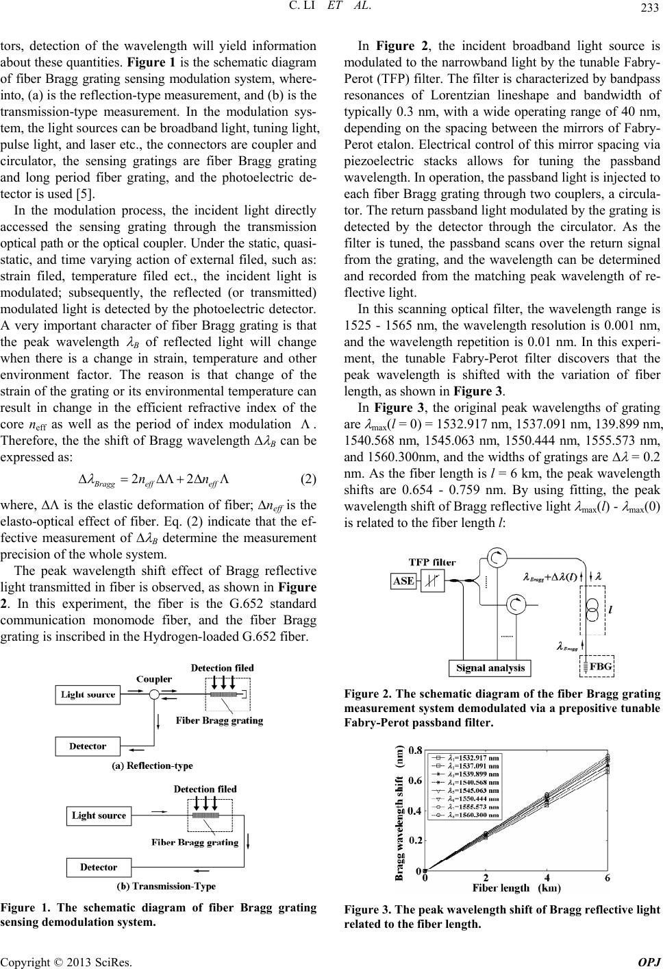 C. LI ET AL. 233 tors, detection of the wavelength will yield information about these quantities. Figure 1 is the schematic diagram of fiber Bragg grating sensing modulation system, where- into, (a) is the reflection-type measurement, and (b) is the transmission-type measurement. In the modulation sys- tem, the light sources can be broadband light, tuning light, pulse light, and laser etc., the connectors are coupler and circulator, the sensing gratings are fiber Bragg grating and long period fiber grating, and the photoelectric de- tector is used [5]. In the modulation process, the incident light directly accessed the sensing grating through the transmission optical path or the optical coupler. Under the static, quasi- static, and time varying action of external filed, such as: strain filed, temperature filed ect., the incident light is modulated; subsequently, the reflected (or transmitted) modulated light is detected by the photoelectric detector. A very important character of fiber Bragg grating is that the peak wavelength B of reflected light will change when there is a change in strain, temperature and other environment factor. The reason is that change of the strain of the grating or its environmental temperature can result in change in the efficient refractive index of the core neff as well as the period of index modulation . Therefore, the the shift of Bragg wavelength B can be expressed as: 22 Bragg effeff nn (2) where, is the elastic deformation of fiber; neff is the elasto-optical effect of fiber. Eq. (2) indicate that the ef- fective measurement of B determine the measurement precision of the whole system. The peak wavelength shift effect of Bragg reflective light transmitted in fiber is observed, as shown in Figure 2. In this experiment, the fiber is the G.652 standard communication monomode fiber, and the fiber Bragg grating is inscribed in the Hydrogen-loaded G.652 fiber. Figure 1. The schematic diagram of fiber Bragg grating sensing demodulation system. In Figure 2, the incident broadband light source is modulated to the narrowband light by the tunable Fabry- Perot (TFP) filter. The filter is characterized by bandpass resonances of Lorentzian lineshape and bandwidth of typically 0.3 nm, with a wide operating range of 40 nm, depending on the spacing between the mirrors of Fabry- Perot etalon. Electrical control of this mirror spacing via piezoelectric stacks allows for tuning the passband wavelength. In operation, the passband light is injected to each fiber Bragg grating through two couplers, a circula- tor. The return passband light modulated by the grating is detected by the detector through the circulator. As the filter is tuned, the passband scans over the return signal from the grating, and the wavelength can be determined and recorded from the matching peak wavelength of re- flective light. In this scanning optical filter, the wavelength range is 1525 - 1565 nm, the wavelength resolution is 0.001 nm, and the wavelength repetition is 0.01 nm. In this experi- ment, the tunable Fabry-Perot filter discovers that the peak wavelength is shifted with the variation of fiber length, as shown in Figure 3. In Figure 3, the original peak wavelengths of grating are max(l = 0 ) = 1532.917 nm, 153 7.0 91 nm, 139. 899 nm, 1540.568 nm, 1545.063 nm, 1550.444 nm, 1555.573 nm, and 1560.300nm, and the widths of gratings are = 0.2 nm. As the fiber length is l = 6 km, the peak wavelength shifts are 0.654 - 0.759 nm. By using fitting, the peak wavelength shift of Bragg reflective light max(l) - max(0) is related to the fiber length l: Figure 2. The schematic diagram of the fiber Bragg grating measurement system demodulated via a prepositive tunable Fabry-Perot passba nd filte r. Figure 3. The peak wavelength shift of Bragg reflective light related to the fiber length. Copyright © 2013 SciRes. OPJ 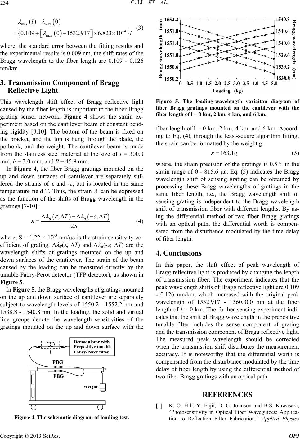 C. LI ET AL. 234 max max 4 max 0 0.10901532.9176.823 10 l l (3) where, the standard error between the fitting results and the experimental results is 0.009 nm, the shift rates of the Bragg wavelength to the fiber length are 0.109 - 0.126 nm/km. 3. Transmission Component of Bragg Reflective L igh t This wavelength shift effect of Bragg reflective light caused by the fiber length is important to the fib er Bragg grating sensor network. Figure 4 shows the strain ex- periment based on the cantilever beam of constant bend- ing rigidity [9,10]. The bottom of the beam is fixed on the bracket, and the top is hung through the blade, the pothook, and the weight. The cantilever beam is made from the stainless steel material at the size of l = 300.0 mm, h = 3.0 mm, and B = 45.9 mm. In Figure 4, the fiber Bragg gratings mounted on the up and down surfaces of cantilever are separately suf- fered the strains of and - , but is located in the same temperature field T. Thus, the strain can b e expressed as the function of the shifts of Bragg wavelength in the gratings [ 7- 1 0]: ,, 2 BB TT S (4) where, S = 1.22 × 10⁻³ nm/ is the strain sensitivity co- efficient of grating, B( , T) and B(- , T) are the wavelength shifts of gratings mounted on the up and down surfaces of the cantilever. The strain of the beam caused by the loading can be measured directly by the tunable Fabry-Perot detector (TFP detector), as shown in Figure 5. In Figure 5, the Bragg wavelengths of gratings mounted on the up and down surface of cantilever are separately subject to wavelength levels of 1550.2 - 1552.2 nm and 1538.8 - 1540.8 nm. In the loading, the solid and virtual line groups denote the wavelength sensitivities of the gratings mounted on the up and down surface with the Figure 4. The schematic diagram of loading test. Figure 5. The loading-wavelength variaiton diagram of fiber Bragg gratings mounted on the cantilever with the fiber length of l = 0 km, 2 km, 4 km, and 6 km. fiber length of l = 0 km, 2 km, 4 km, and 6 km. Accord- ing to Eq. (4), through the least-square algorithm fitting, the strain can be formatted by the weight g: 163.1 g (5) where, the strain precision of the gratings is 0.5% in the strain range of 0 - 815.6 . Eq. (5) indicates the Bragg wavelength shift of sensing grating can be obtained by processing these Bragg wavelengths of gratings in the same fiber length, i.e., the Bragg wavelength shift of sensing grating is independent to the Bragg wavelength shift of transmission fiber with different lengths. By us- ing the differential method of two fiber Bragg gratings with an optical path, the differential worth is compen- sated from the disturbance modulated by the time delay of fiber length. 4. Conclusions In this paper, the shift effect of peak wavelength of Bragg reflective light is produced by changing the length of transmission fiber. The experiment indicates that the peak wavelength shifts of Br agg ref lec tive lig ht ar e 0.109 - 0.126 nm/km, which increased with the original peak wavelength of 1532.917 - 1560.300 nm at the fiber length of l = 0 km. The further sensing experiment indi- cates that the shift of Bragg wavelength in the prepositive tunable filter includes the sense component of grating and the transmission component of Bragg reflective lig ht. The measured peak wavelength should be corrected when the transmission shift distributes the measurement accuracy. It is noteworthy that the differential worth is compensated from the disturbance modulated by the time delay of fiber length by using the differential method of two fiber Bragg gratings with an optical path. REFERENCES [1] K. O. Hill, Y. Fujii, D. C. Johnson and B.S. Kawasaki, “Photosensitivity in Optical Fiber Waveguides: Applica- tion to Reflection Filter Fabrication,” Applied Physics Copyright © 2013 SciRes. OPJ  C. LI ET AL. Copyright © 2013 SciRes. OPJ 235 Letters, Vol. 32, No. 10, 1978, pp. 647-649. doi:10.1063/1.89881 [2] G. Meltz, W. W. Morey, W. H. Glenn and J. D. Farina . Davis, H. J. Patrick, M. LeBlanc, K. , “In-Fiber Bragg-Grating Temperature and Strain Sensors, Instrumentation in the Aerospace Industry,” Vol. 34, No.2, 1988, pp. 239-242. [3] A. D. Kersey, M. A P. Koo, C. G. Askins, M. A. Putnam and E. Joseph Frie- bele, “Fiber grating sensors,” IEEE Journal of Lightwave Technology, Vol. 15, No. 8, 1997, pp. 1442-1463. doi:10.1109/50.618377 [4] T. Erdogan, “Fiber Grating Spectra,” IEEE Journal of Lightwave Technology, Vol. 15, No. 8, 1997, pp. 1277-1294. doi:10.1109/50.618322 [5] C. Li, Y. M. Zhang, Y. G. Zhao and L. J. Li, “Fiber grat- l. 29, No. 1, 1993, pp. 47-49. ing: Principles, Techniques and Applications,” Science Press, Beijing, 2005. [6] H. G. Limberger, P. Y. Fonjallaz and R. P. Salathe, “Spectral Characterisation of Photoinduced High Effi- cient Bragg Gratings in Standard Telecommunication Fi- bres,” Electronics Letters, Vo doi:10.1049/el:19930031 [7] V. Gaillarda, X. Aduriza, N. Daherab, et al., “Local and Spectral Characterization of Optical Fibers and Fiber Bragg Gratings with Low Coherence Interferometry,” Fiber and Integrated Optics, Vol. 28, No. 1, 2008, pp. 108-126. doi:10.1080/01468030802272 575 [8] Y. L. Lo, J. F. Huang, P. H. Sung and M. D. Yang, “In- tensity Effects in Bragg Grating Sensors Scanned by a Tunable Filter,” Measurement Science a Vol. 11, No. 10, 2000, pp. 1456-1462. nd Technology, doi:10.1088/0957-0233/11 / 10/306 |