

Paper Menu >>
Journal Menu >>
 Optics and Photonics Journal, 2013, 3, 187-191 doi:10.4236/opj.2013.32B045 Published Online June 2013 (http://www.scirp.org/journal/opj) Copyright © 2013 SciRes. OPJ Nonlinear Polarization Rotation Characteristic Phenomenon in a Bulk Semiconductor Optical Amplifier Xanghua Feng1, Jiarong Ji2, Guomin Zhang1 1College of Science,Informa t ion E ng ineeri ng Univer si ty, Zhengzhou, China 2College of Opto electronic Science and Engineering National University of Defense Technology, Changsha, China Email: [email protected] Received 2013 ABSTRACT The phenomena of polarization rotation induced by self-modulation in se miconducto r optical amplifier (SOA) are ana- lyzed theoretically. The relationship between polarization parameters and gain as well as phase is obtained by the cor- relation parameter of ellipse polarization and SOA nonlinearity polarization rotation theory. The experiment employs polarizer drive by walking electromotor and power meter, the light power of 360 degree is measured. The transforma- tion law of output polarization power components is found for obvious polarization rotation in the selected coordinate axes based on connection of polarization state in difference axes. U sing this law make the manipulation easily on get- ting ideal polarization state. It can offer a fine method to realize all-optical switch and other logic elements in experi- ment. This work is of great significance for the applications of SOA nonlinear polarization rotation at high-speed all-optical signal processing and all-optical logic gate. Keywords: Strai ned Bulk S OA; Nonlinear Polariz a tion Rotation; Phase Difference; Polar izatio n Azimuth 1. Introduction H.Soto and D.Erasme [1] first raised a concept of cross- polariza tio n-modulatio n (X PolM) in 1999. They investi- gate the transformation law of SOA birefraction with Jone–matrix. The nonlinear polarization rotation induced by SOA birefraction was used on all-optical wavelength conve rsion, switch, l ogic gate in the paper [2,3]. From 2003, Dorren [4,5] et al. researched all-logic ele- ments and all-optical switch base on XP o lM in theory and experiment, and raised a theory model for polariza- tion depende nt gai n saturation in te nsile strai n bulk SO A. L.Q.Guo et al. set a 2.5 Gbit/s all-optical AND gate base on XPolM [6-8]. They proved extinction ratio increased 8dB contrast all-optical AND gate base on cross-gain- modulation. Due to the polarization rotation can induce the variety of output power, the polarization rota tion co m- bining other non-linearity effect can use in all-optical nonlinear regeneration [9] and all-optical sampling [10] and optical buffer [11] and optical data comparator [12]. Recently, with investigate deeply, the applications of SOA nonlinear polarization rotation at high-speed all-optical signal processing and all-optical logic are more and more widespread along with research deeply [13,14]. 2. Theory Model and Simulations The tensile strain bulk SOA is used for experime nt. Based on Dorren’s theory, The polarized optical field are de- composed into a transverse electric (TE) and trans- verse magnetic (TM) component. TE and TM mode propagate “independently” through the SOA, although they have indirect interaction with each other via the gain satura- tion. Because of different confinement factor and effec- tive refractive indexes experienced by TE and TM modes, it results in a phase shift TE and TM modes of the light upon leaving the SOA. When a light transit SOA, the out powers for each polarization can be expressed as: int ( )( )exp() TE TETE TE TE out in g gL PP v ττ α Γ = − (1) int ( )( )exp() TM TMTM TM TM out in g gL PP v ττ α Γ = − (2) where Pin is input power, Pout is output power, Γ is the confinement factor, g is the gain, L is the length of the SOA. By relation of gain and phase, output phase through L can be expressed as 0 2 TE TE TE TE TE g g L v α φφ Γ = − (3) 0 2 TM TMTM TM TM g g L v α φφ Γ = − (4) where α is phase modulation coefficients, it express the 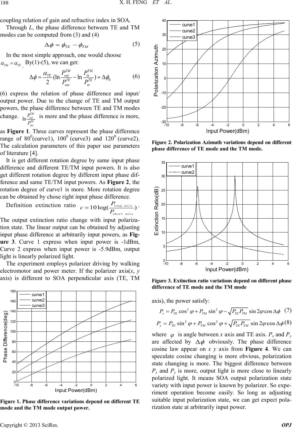 X. H. FENG ET AL. Copyright © 2013 SciRes. OPJ 188 coupling rel atio n of gain and refractive index in SOA. Through L, the phase difference between TE and TM modes can be computed from (3) and (4) TMTE φφφ −=∆ (5) In the most simple approach, one would choose TM TE αα = . By(1)-(5), we can get: 0 (lnln ) 2 TM TM out in TE TE TE out in PP PP α φφ ∆ =−+∆ (6) (6) express the relation of phase difference and input/ output power. Due to the change of TE and TM output powers, the phase difference between TE and TM modes change. ln TM out TE out P P is more and the phase difference is mo r e, as Figure 1. Three curves represent the phase difference range of 800(curve1), 1000 (curve3) and 1200 (curve2). The calculation parameters of this paper use parameters of literature [4 ] . It is get different rotation degree by same input phase difference and different TE/TM input powers. It is also get different rotation degree by differe nt input phase dif- ference and same TE/TM input powers. As Figure 2, the rotation degree of curve1 is more. More rotation degree can be obtained by chose right input phase difference. Definition extinction ratio 10log( ) P cP = long axis short axis . The output extinction ratio change with input polariza- tion state. The linear output can be obtained by adjusting input phase difference at arbitrarily input powers, as Fig- ure 3. Curve 1 express when input power is -1dBm, Curve 2 express when input power is -5.9dBm, output light is linearly polarized light. The experiment employs polarizer driving by walking electromotor and power meter. If the polarizer axis(x, y axis) is different to SOA perpendicular axis (TE, TM -10-8 -6 -4-20 2 46 0 20 40 60 80 100 120 140 160 180 In put Power(dBm) Phase Difference(deg) curve 1 curve 2 curve 3 Figure 1. P hase dif fere nce va riations d epen d on diff erent TE mode and the TM mode output po wer. -10 -8 -6 -4 -2 0246 -30 -20 -10 0 10 20 30 40 In put P ower (dB m ) Pol arizat ion A zim uth curve1 curve2 curve3 Figure 2. Polarization Azimuth variations depend on different phase difference of TE mode and the TM mode. -10 -8 -6 -4 -2 0246 0 5 10 15 20 25 30 35 In put Power (dB m ) Ext inction Ratio(dB ) curve1 curve2 Figure 3. Extinction ratio variations depend on different phase difference of TE mode and the TM mode axis), the power satisfy: 22 cossinsin 2cos xTETMTE TM P PPPP ϕ ϕϕφ =+− ∆ (7) 22 sincossin 2cos yTETMTE TM P PPPP ϕ ϕϕφ =++ ∆ (8) where ϕ is angle between x axis and T E axi s. Px and Py are affected by φ ∆ obviously. The phase difference cosine law appear on x y axis from Figure 4. We can speculate cosine changing is more obvious, polarization state changing is more. The biggest difference between Px and Py is more, output light is more close to linearly polarized light. It means SOA output polarization state variety with input power is known by polarizer. So expe- riment operation become easily. So long as adjusting suitable input polarization state, we can get expect pola- rization state at ar bitrarily input power. 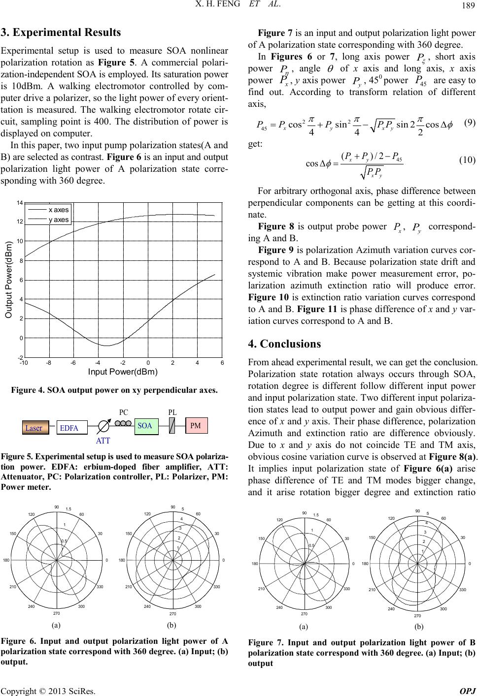 X. H. FENG ET AL. Copyright © 2013 SciRes. OPJ 189 3. Experimental Results Experimental setup is used to measure SOA nonlinear polarization rotation as Figure 5. A commercial polari- zation-independent SOA is employed. Its saturation power is 10dBm. A walking electromotor controlled by com- puter drive a polarizer, so the light power of every orient- tation is measured. The walking electromotor rotate cir- cuit, sampling point is 400. The distribution of power is displayed on computer. In this paper, two input pump polarization states(A and B) are selected as contra st. Figure 6 is an input and output polarization light power of A polarization state corre- sponding with 360 degree. -10 -8-6-4-20 2 4 6 -2 0 2 4 6 8 10 12 14 In put Power (dB m ) Output P ower(dBm) x axes y axes Figure 4. SOA output power o n xy perpendic ular a xes. Laser EDFA SOA ATT PM PC PL Figure 5. Experimental setup is used to measure SOA polariza- tion power. EDFA: erbium-doped fiber amplifier, ATT: Attenuat or, PC: Polarizati on co ntroller, PL: Polarizer, PM : Power meter. 0.5 1 1.5 30 210 60 240 90 270 120 300 150 330 180 0 1 2 3 4 5 30 210 60 240 90 270 120 300 150 330 180 0 (a) (b) Figure 6. Input and output polarization light power of A polarizatio n state co rres pond w it h 36 0 degree. (a) Input; (b) output. Figure 7 is an input and output polarization light power of A polarization state corresponding with 360 degree. In Figures 6 or 7, long axis power P ξ , short axis power P η , angle θ of x axis and long axis, x axis power x P , y axis power y P , 450 power 45 P are easy to find out. According to transform relation of different axis, 22 45 cossinsin 2cos 44 2 x yxy P PPPP ππ π φ = +−∆ (9) get: 45 ( )/2 cos xy xy PP P PP φ +− ∆= (10) For arbitrary orthogonal axis, phase difference betwee n perpendicular components can be getting at this coordi- nate. Figure 8 is output probe power x P , y P correspond- ing A and B. Figure 9 is polarization Azimuth variatio n curves cor- respond to A and B. Because polarization state drift and systemic vibration make power measurement error, po- larization azimuth extinction ratio will produce error. Figure 10 is extinction ratio variation curves correspond to A and B. Figure 11 is phase difference of x and y var- iation curves correspond to A and B. 4. Conclusions From ahead experimental resul t, we can get the conclusion. Polarization state rotation always occurs through SOA, rotation degree is different follow different input power and input po lariza tion sta te. Two d iffere nt i nput polar iza- tion states lead to output power and gain obvious differ- ence of x and y axis. Their phase difference, polarization Azimuth and extinction ratio are difference obviously. Due to x and y axis do not coincide TE and TM axis, obvious cosine variation curve is observed at Figure 8(a). It implies input polarization state of Figure 6(a) arise phase difference of TE and TM modes bigger change, and it arise rotation bigger degree and extinction ratio 0.5 1 1.5 30 210 60 240 90 270 120 300 150 330 180 0 1 2 3 4 5 30 210 60 240 90 270 120 300 150 330 180 0 (a) (b) Figure 7. Input and output polarization light power of B polarizati o n state corres p ond w ith 36 0 degree. (a) Input; ( b) output 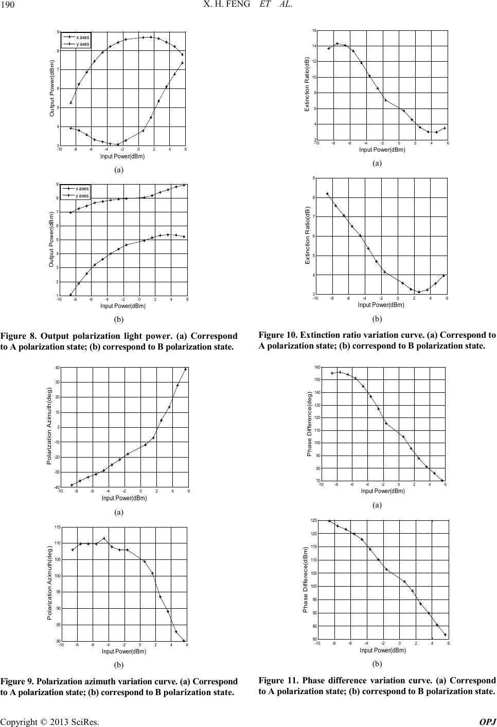 X. H. FENG ET AL. Copyright © 2013 SciRes. OPJ 190 -10 -8-6-4-20 2 46 3 4 5 6 7 8 9 Input P ower(dB m ) Out put Power(dBm) x axes y axes (a) -10 -8 -6 -4 -2 0246 1 2 3 4 5 6 7 8 9 Input P ower(dB m ) Out put Power(dBm) x axes y axes (b) Figure 8. Output polarization light power. (a) Correspond to A polarization state; (b) correspond to B polarization state. -10 -8-6-4-20 2 46 -40 -30 -20 -10 0 10 20 30 40 Input Power(dBm ) Polarizat ion Azi m uth(deg) (a) -10 -8 -6 -4 -202 4 6 80 85 90 95 100 105 110 115 Input P ower(dB m ) Polarizat ion Azi m uth(deg) (b) Figure 9. Polarization azimuth variation curve. (a) Correspond to A polarization state; (b) correspond to B polari zati on state. -10 -8 -6 -4 -2 0246 2 4 6 8 10 12 14 16 Input P ower(dBm ) Extincti on Ratio( dB ) (a) -10 -8-6-4 -20 2 46 3 4 5 6 7 8 9 Input P ower( dBm ) Extincti on Ratio( dB ) (b) Figure 10. Extinction ratio variation curve. (a) Correspond to A polarization state; (b) correspond to B polarization state. -10-8 -6 -4 -20 2 4 6 70 80 90 100 110 120 130 140 150 160 Input P ower(dB m ) Phase Di fference( de g) (a) -10 -8-6-4-20 2 4 6 80 85 90 95 100 105 110 115 120 125 Input Power(dBm ) Phase Di ff erece(dBm) (b) Figure 11. Phase difference variation curve. (a) Correspond to A polarization state; (b) correspond to B polarization s tate .  X. H. FENG ET AL. Copyright © 2013 SciRes. OPJ 191 bigger change. Cosine variation curve is not observed at Figure 8 (b). It implies input p olarization state of Figure 7(a) do not arise phase difference of TE and TM modes bigger change, and it not arise rotation and extinction ratio bigger change. Thus it can be seen, if input polari- zation state arise phase difference of TE and TM modes bigger change, output powers at x axis or y axis appear cosine variation. It proves in theory and experiment, ar- bitrary output probe polarization states can be obtained through adjusting input pump polarization states. In ex- periment, the adjusting of polarization states can mani- pulate easily base on transform relation of different coor- dinate syste m. REFERENCES [1] H.Soto, D. Erasme and G. C. Guekos, “Cross-Polarization Modulation in Semiconductor Optical Amplifiers,” IEEE Photonics Technology Letters, vol. 11, No. 8, 1999, pp. 970-972. [2] H. Soto, D. Erasme, G. C. Guekos, et a1., “5-Gb/s XOR Optical Gate Based on Cross-Polarization Modulation in Semiconductor Optical Amplifiers,” IEEE Photonics Techn ology Letters, Vo l. 13, No. 4, 2001, pp. 335-337. doi:10.1109/68.775316 doi:10.1109/68.917843 [3] H. Soto, C. A. Diaz, J. Topomondzo, et a1. “All-Optical AND Gate Implementation Using Cross-Polarization Modulation in A Semiconductor Optical Amplifier,” IEEE Photonic Technology Letters, Vol. 14, No. 4, 2002, pp. 498-500. doi:10.1109/68.992590 [4] H. J. S. Dorren, D. Lenstra, Y. Liu, “Nonlinear Polariza- tion Rotation in Semiconductor Optical Amplifiers: Theory and Application to All-Optical Flip-Flop Memo- ries,” IEEE Journal of Quantum Electronics, Vol. 39, No. 1, 2003, pp. 141-148. doi:10.1109/JQE.2002.806200 [5] H. J. S. Dorren, X. L. Yang and A. K. Mishra, “A11- Optical Logic Based on Ultrafast Gain and Index Dy- namics in a Semiconductor Optical Amplifier,” IEEE Journal of Selected Topics in Quantum Electronics, Vol. 10, No. 5, 2004, pp. 1079-1092. [6] L. Q. Guo and M. J. Connelly, “All-Optical AND Gate with Improved Extinction Ratio Using Signal Induced Nonlinearities in A Bulk Semiconductor Optical Am- plifier,” Optical Express, Vol. 14, No. 7, 2006, pp. 2938-2943. doi:10.1109/JSTQE.2004.835293(410)1 doi:10.1364/OE.14.002938 [7] L. Q. Guo and M. J. Connelly, “A Mueller-Matrix For- malism for Modeling Polarization Azimuth and Ellipticity Angle in Semiconductor Optical Amplifiers in a Pump–Pr obe S cheme,” Journal of Lightwave Technology, Vol. 25, No. 1, 2007, pp. 410-420. doi:10.1109/JLT.2006.886674 [8] L. Q. Guo and M. J. Connelly, “A Poincare Approach to Investigate Nonlinear Polarization Rotation in Semicon- ductor Optical Amplifiers and Its Application to All-Optical Wavelength Conversion,” Proceedings of SPIE, Vol. 6783, No. 678325, 2007, pp. 1-5. doi:10.1117/12.745453 [9] P. Morin, J. Fatome, C. Finot, et al., “All-Optical Nonli- near Processing of Both Polarization State and Intensity Profile for 40 Gbit/s Regeneration Applications,” Optics Express, Vol. 19, No. 18, 2011, pp. 17158-17166. doi:10.1364/OE.19.017158 [10] S. Zhang, Y. Liu, et al., “All-Optical Sampling Based on Nonlinear Polarization Rotation in Semiconductor Optical Amplifiers,” Journal of Optoelectronics and Biomedical Materials, Vol. 1, No. 4, 2009, pp. 383-388. [11] M. Cheng, C. Q. Wu, et al., “Cascaded Optical Buffer Based on Nonlinear Polarization Rotation in Semicon- ductor Optical Amplifiers,” Chinese. Physics. Letters, Vol. 25, No. 11, 2008, pp. 4026-4629. doi:10.1088/0256-307X/25/11/052 [12] S. K. Garai, “A Method of Developing Frequency En- coded Multi-Bit Optical Data Comparator Using Semi- conductor Optical Amplifier,” Optics & Laser Technolo- gy, Vol. 43, No. 1, 2011, pp. 124-131. doi:10.1016/j.optlastec.2010.05.016 [13] L. L. Yi, W.S. Hu, et al., “All-Optical Reconfigurable Multi-Logic Gates Based on Nonlinear Polarization Rota- tion Effect in A Single SOA,” Chinese Optics Letters, Vol. 9, No. 3, 2011, pp.030603(1-4). [14] Z. Y. Li, C. Q . Wu, H. Dong, et a1.,“Matrix Analysis for Polarization Rotation of Semiconductor Optical Amplifi- ers with Related Application,” Chinese J. Las ers, Vo l. 36, No. 4, 2009, pp. 842-845. doi:10.3788/CJL20093604.0842 [15] S. K. Garai, P. Ghosh and S. Mukhopadhyay, “Analytical Approach of Developing Wavelength Encoded AND, NAND and X-OR Logic Operations and Implementation of the Theory Using Semiconductor Optical Amplifiers,” Optik, Vol. 122, No. 7, 2011, pp. 569-576. doi:10.1016/j.ijleo.2010.04.012 |