

Paper Menu >>
Journal Menu >>
 Optics and Photonics Journal, 2013, 3, 112-117 doi:10.4236/opj.2013.32B028 Published Online June 2013 (http://www.scirp.org/journal/opj) System-on-a-Chip (SoC) Based Hardware Acceleration for Video Codec Xinwei Niu, Jeffrey Fan Department of Electrical and Computer Engineering, Florida International University, Miami, USA Email: [email protected], [email protected] Received 2013 ABSTRACT Nowadays, from home monitoring to large airport security, a lot of digital video surveillance systems have been used. Digital surveillance system usually requires streaming video pro cessing abilities. As an advanced v ideo cod ing method, H.264 is introduced to reduce the large video data dramatically (usually by 70X or more). However, computational overhead occurs when coding and decoding H.264 video. In this paper, a System-on-a-Chip (SoC) based hardware ac- celeration solution for video codec is proposed, which can also be used for other software applications. The characteris- tics of the video codec are analyzed by using the profiling tool. The Hadamard function, which is the bottleneck of H.264, is identified not only by execution time but also another two attributes, such as cycle per loop and loop round. The Co-processor approach is applied to accelerate the Hadamard function by transforming it to hardware. Performance improvement, resource costs and energy consumption are compared and analyzed. Experimental results indicate that 76.5% energy deduction and 8.09X speedup can be reached after balancing these three key factors. Keywords: SoC; Software Profiling; Hardware Acceleration; Video Codec 1. Introduction System-on-a-Chip (SoC) refers to integrating all compo- nents of a computer or other electronic systems into a single integrated circuit (chip). The SoC designer’s role is to integrate all the parts into a chip to implement so- phisticated functions in a relatively short time [1]. To- day’s computer system is much more complicated and powerful than those in 1990s. Obviously, the old MPEG-2 standard is not an efficient video standard any more for the novel technology. That is why there is a new video coding standard, called H.264/MPEG-4 Part 10 Advanced Vi deo Coding (AVC) or just H.264 [2] . The increased customer demands for advanced SoC devices result in shorter design cycle and time-to-market schedule. There is a demand that the final product should have the optimized partition of hardware and software. Profiling plays an important role because it determines the bottleneck of the whole system. It is helpful for de- signers to keep the balance between the hardware and the software. Thus, better overall system performance with little overhead can be achieved [3]. Hardware acceleration has trade-offs. Implementing the whole algorithm on hardware is time saving but with less flexibility. General purpose hardware provides great flexibility but it is time-consuming for software applica- tion. So it is importan t to balance the trade-offs of a sys- tem when constructing a hardware accelerator. There are several previous researches about the soft- ware profiling and hardware acceleration for video codec. It was found that hotspot functions can be chosen based on the execution time [4,5]. Some authors said the hot- spot functions can be identified by monitoring the loop rounds [6,7]. However, their methods are not accurate enough to identify the hotspot functions. Functions with high execution time or loop rounds cannot be viewed as the most suitable candidates for hardware acceleration. A general hardware acceleration approach was presented by Chen et al. [8]. They used the pipeline to accelerate the system, but their hardware accelerator was connected to the system bus, so that the processing time might be in- fluenced if other peripherals would like to communicate with processor at the same time. Besides, the function they choose is not the real hotspot function in H.264. Kordasiewicz et al. showed the speed and area optimiza- tions for H.264 Discrete Cosine Transform (DCT) and quantization blocks [9], but DCT may not be the most suitable function to be accelerated in H.264. Elgato [10] has a USB thumb disk that acts as an H.264 hardware accelerator. Even though the USB 2.0 bus processes about 25 MB/s - 30 MB/s of bandwidth, the bandwidth of Northbridge can take up to 2132 MB/s, which is about 700 times faster than the USB bus as a peripheral bus. Not to mention that if we implement the chip into the Northbridge, it will bring a lot of compatibil ity problems Copyright © 2013 SciRes. OPJ 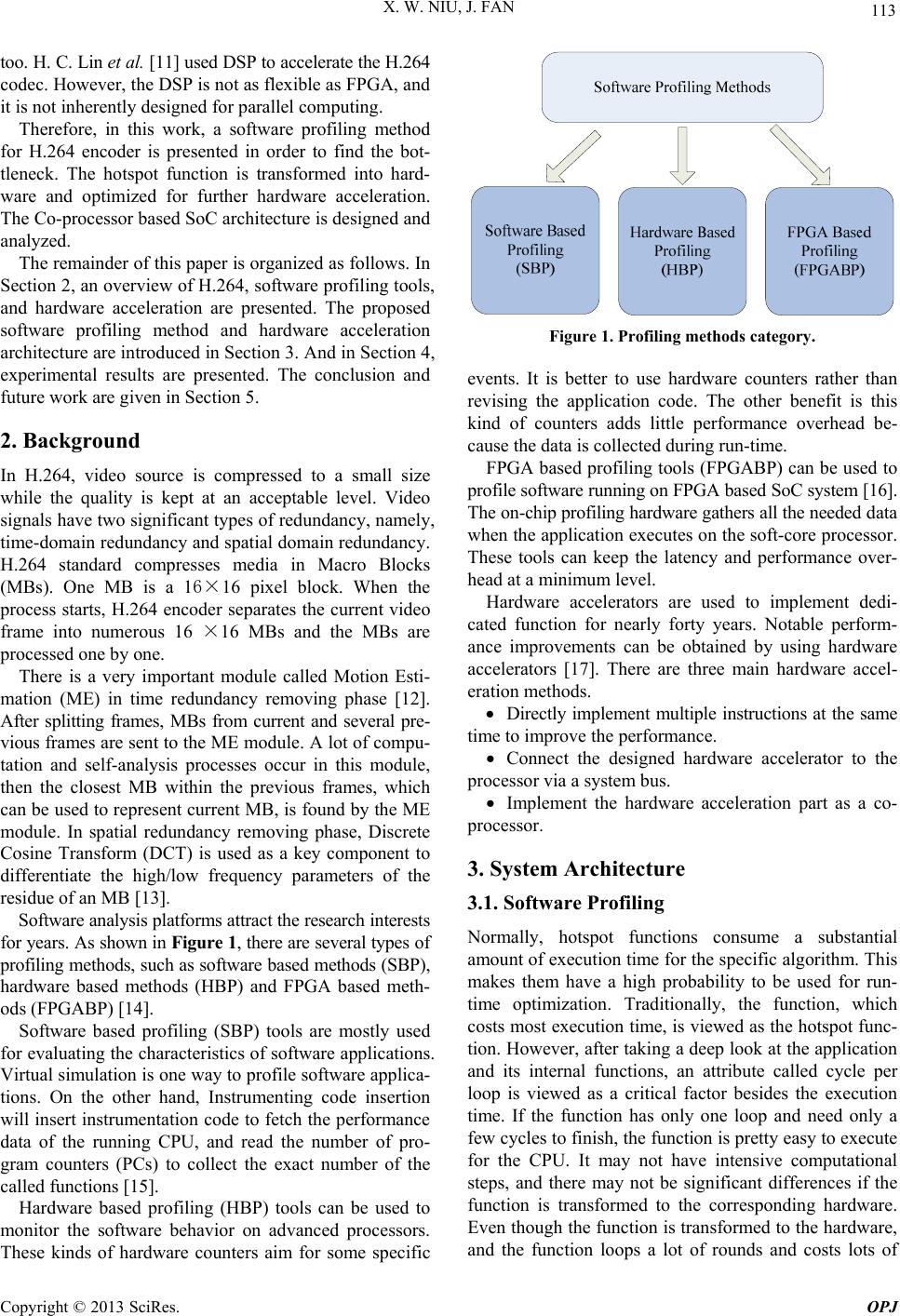 X. W. NIU, J. FAN 113 too. H. C. Lin et al. [11] used DSP to accelerate the H.264 codec. However, the DSP is not as flexible as FPGA, and it is not inherently design ed for parallel computing. Therefore, in this work, a software profiling method for H.264 encoder is presented in order to find the bot- tleneck. The hotspot function is transformed into hard- ware and optimized for further hardware acceleration. The Co-processor based SoC architecture is designed and analyzed. The remainder of this paper is organized as follows. In Section 2, an overview of H.264, software profiling tools, and hardware acceleration are presented. The proposed software profiling method and hardware acceleration architecture are introduced in Section 3. And in Section 4, experimental results are presented. The conclusion and future work are given in Section 5. 2. Background In H.264, video source is compressed to a small size while the quality is kept at an acceptable level. Video signals have two significant types of red undancy, namely, time-domain redundancy and spatial domain redundancy. H.264 standard compresses media in Macro Blocks (MBs). One MB is a 16×16 pixel block. When the process starts, H.264 encoder separates the current video frame into numerous 16 ×16 MBs and the MBs are processed one by one. There is a very important module called Motion Esti- mation (ME) in time redundancy removing phase [12]. After splitting frames, MBs from current and several pre- vious frames are sent to the ME module. A lot of compu- tation and self-analysis processes occur in this module, then the closest MB within the previous frames, which can be used to represent current MB, is found by the ME module. In spatial redundancy removing phase, Discrete Cosine Transform (DCT) is used as a key component to differentiate the high/low frequency parameters of the residue of an MB [13]. Software analysis platforms attract the resear ch in terests for years. As shown in Figure 1, there are several types of profiling methods, such as software based methods (SBP), hardware based methods (HBP) and FPGA based meth- ods (FPGABP) [14]. Software based profiling (SBP) tools are mostly used for evaluating the characteristics of software applications. Virtual simulation is one way to profile software applica- tions. On the other hand, Instrumenting code insertion will insert instrumentation code to fetch the p erformance data of the running CPU, and read the number of pro- gram counters (PCs) to collect the exact number of the called functions [15]. Hardware based profiling (HBP) tools can be used to monitor the software behavior on advanced processors. These kinds of hardware counters aim for some specific Figure 1. Profiling methods category. events. It is better to use hardware counters rather than revising the application code. The other benefit is this kind of counters adds little performance overhead be- cause the data is collected during run-time. FPGA based profiling too ls (FPGABP) can be used to profile software running on FPGA based SoC system [16]. The on-chip profiling hardware gathers all the needed d a ta when the application executes on the soft-core processor. These tools can keep the latency and performance over- head at a minimum level. Hardware accelerators are used to implement dedi- cated function for nearly forty years. Notable perform- ance improvements can be obtained by using hardware accelerators [17]. There are three main hardware accel- eration methods. Directly implement multiple instructions at the same time to improve the performance. Connect the designed hardware accelerator to the processor via a system bus. Implement the hardware acceleration part as a co- processor. 3. System Architecture 3.1. Software Profiling Normally, hotspot functions consume a substantial amount of execution time for the specific algorithm. This makes them have a high probability to be used for run- time optimization. Traditionally, the function, which costs most execution time, is viewed as the hotspot func- tion. However, after taking a deep look at the application and its internal functions, an attribute called cycle per loop is viewed as a critical factor besides the execution time. If the function has only one loop and need only a few cycles to finish, the function is pretty easy to execute for the CPU. It may not have intensive computational steps, and there may not be significant differences if the function is transformed to the corresponding hardware. Even though the function is transformed to the hardware, and the function loops a lot of rounds and costs lots of Copyright © 2013 SciRes. OPJ 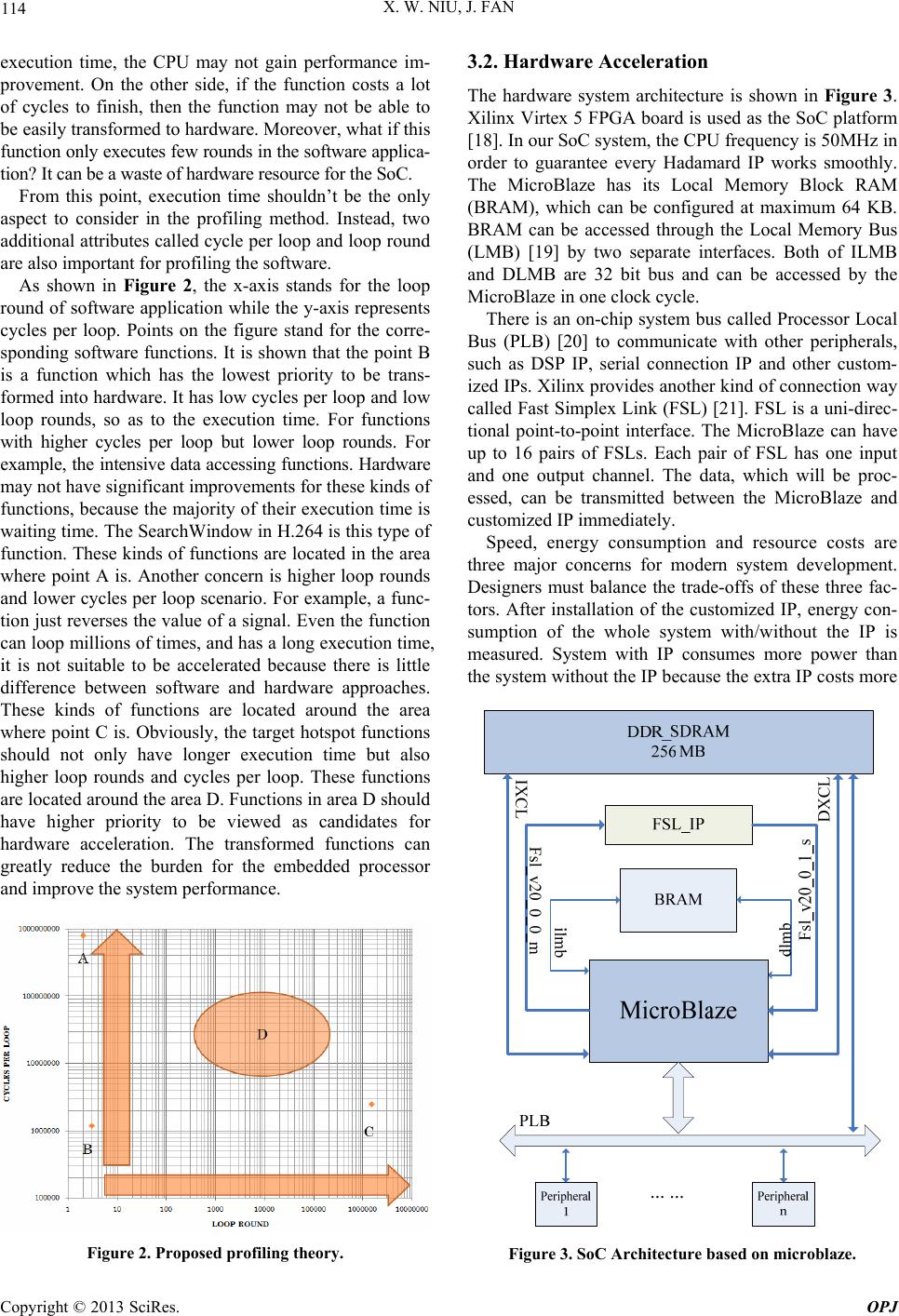 X. W. NIU, J. FAN 114 execution time, the CPU may not gain performance im- provement. On the other side, if the function costs a lot of cycles to finish, then the function may not be able to be easily transformed to hardware. Moreover, what if this function only executes few rounds in the software applica- tion? It can be a waste of hardware resource for the SoC. From this point, execution time shouldn’t be the only aspect to consider in the profiling method. Instead, two additional attributes called cycle per loop and loop round are also important for profiling the software. As shown in Figure 2, the x-axis stands for the loop round of software application while th e y-axis represents cycles per loop. Points on the figure stand for the corre- sponding software functions. It is shown that the point B is a function which has the lowest priority to be trans- formed into hardware. It has low cycles per loop and low loop rounds, so as to the execution time. For functions with higher cycles per loop but lower loop rounds. For example, the intensive data accessing functions. Hardware may not have significant improvements for these kinds of functions, because the majority of their execution time is waiting time. The SearchWindow in H.264 is this type of function. These kinds of functions are located in the area where point A is. Another concern is higher loop rounds and lower cycles per loop scenario. For example, a func- tion just reverses the value of a signal. Even the function can loop millions of times, and has a long execu tion time, it is not suitable to be accelerated because there is little difference between software and hardware approaches. These kinds of functions are located around the area where point C is. Obviously, the target hotspot functions should not only have longer execution time but also higher loop rounds and cycles per loop. These functions are located around the area D. Functions in area D should have higher priority to be viewed as candidates for hardware acceleration. The transformed functions can greatly reduce the burden for the embedded processor and improve the system performance. Figure 2. Proposed profiling theory. 3.2. Hardware Acceleration The hardware system architecture is shown in Figure 3. Xilinx Virtex 5 FPGA board is used as the SoC platform [18]. In our SoC system, the CPU frequency is 50MHz in order to guarantee every Hadamard IP works smoothly. The MicroBlaze has its Local Memory Block RAM (BRAM), which can be configured at maximum 64 KB. BRAM can be accessed through the Local Memory Bus (LMB) [19] by two separate interfaces. Both of ILMB and DLMB are 32 bit bus and can be accessed by the MicroBlaze in one clock cycle. There is an on-chip system bus called Processor Local Bus (PLB) [20] to communicate with other peripherals, such as DSP IP, serial connection IP and other custom- ized IPs. Xilinx provid es another kind o f connection way called Fast Simplex Link (FSL) [21]. FSL is a uni-direc- tional point-to-point interface. The MicroBlaze can have up to 16 pairs of FSLs. Each pair of FSL has one input and one output channel. The data, which will be proc- essed, can be transmitted between the MicroBlaze and customized IP immediately. Speed, energy consumption and resource costs are three major concerns for modern system development. Designers must balance the trade-offs of these three fac- tors. After installation of the customized IP, energy con- sumption of the whole system with/without the IP is measured. System with IP consumes more power than the system without the IP because the extra IP costs more Figure 3. SoC Architecture based on microblaze. Copyright © 2013 SciRes. OPJ 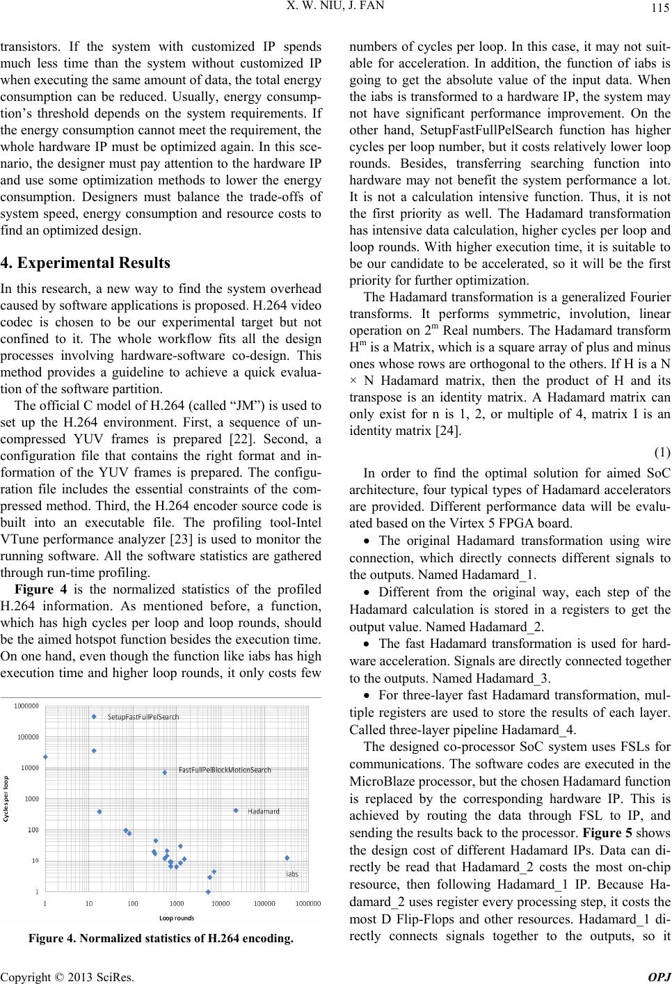 X. W. NIU, J. FAN 115 transistors. If the system with customized IP spends much less time than the system without customized IP when executing the same amount of da ta, the total en erg y consumption can be reduced. Usually, energy consump- tion’s threshold depends on the system requirements. If the energy consumption cannot meet the requirement, the whole hardware IP must be optimized again. In this sce- nario, the designer must pay attention to the hardware IP and use some optimization methods to lower the energy consumption. Designers must balance the trade-offs of system speed, energy consumption and resource costs to find an optim ized design. 4. Experimental Results In this research, a new way to find the system overhead caused by software applications is proposed. H.264 video codec is chosen to be our experimental target but not confined to it. The whole workflow fits all the design processes involving hardware-software co-design. This method provides a guideline to achieve a quick evalua- tion of the software partition. The official C model of H.264 (called “JM”) is used to set up the H.264 environment. First, a sequence of un- compressed YUV frames is prepared [22]. Second, a configuration file that contains the right format and in- formation of the YUV frames is prepared. The configu- ration file includes the essential constraints of the com- pressed method. Third, the H.264 encoder source code is built into an executable file. The profiling tool-Intel VTune performance analyzer [23] is used to monitor the running software. All the software statistics are gathered through run- time profiling. Figure 4 is the normalized statistics of the profiled H.264 information. As mentioned before, a function, which has high cycles per loop and loop rounds, should be the aimed hotspot function besides the execu tion time. On one hand, even though the function like iabs has high execution time and higher loop rounds, it only costs few Figure 4. Normalized statistics of H.264 encoding. numbers of cycles per loop. In this case, it may not suit- able for acceleration. In addition, the function of iabs is going to get the absolute value of the input data. When the iabs is transformed to a hardware IP, the system may not have significant performance improvement. On the other hand, SetupFastFullPelSearch function has higher cycles per loop number, but it costs relatively low er loop rounds. Besides, transferring searching function into hardware may not benefit the system performance a lot. It is not a calculation intensive function. Thus, it is not the first priority as well. The Hadamard transformation has intensive data calculation, higher cycles per loop and loop rounds. With higher execution time, it is suitable to be our candidate to be accelerated, so it will be the first priority for further optimizatio n. The Hadamard transformation is a generalized Fourier transforms. It performs symmetric, involution, linear operation on 2m Real numbers. The Hadamard transform Hm is a Matrix, which is a square array of plus and minus ones whose rows are orthogonal to the others. If H is a N × N Hadamard matrix, then the product of H and its transpose is an identity matrix. A Hadamard matrix can only exist for n is 1, 2, or multiple of 4, matrix I is an identity matrix [24]. (1) In order to find the optimal solution for aimed SoC architecture, four typical types of Hadamard accelerators are provided. Different performance data will be evalu- ated based on the Virtex 5 FPGA board. The original Hadamard transformation using wire connection, which directly connects different signals to the outputs. Named Hadamard_1. Different from the original way, each step of the Hadamard calculation is stored in a registers to get the output val ue. Name d Hadamard_2. The fast Hadamard transformation is used for hard- ware acceleration. Signals are directly connected together to the outputs. Named Hadam ard_3. For three-layer fast Hadamard transformation, mul- tiple registers are used to store the results of each layer. Called three-layer pipeline Hadamard_4. The designed co-processor SoC system uses FSLs for communications. The software codes are executed in the MicroBlaze processor, but the chosen Hadamard function is replaced by the corresponding hardware IP. This is achieved by routing the data through FSL to IP, and sending the results back to the processor. Figure 5 shows the design cost of different Hadamard IPs. Data can di- rectly be read that Hadamard_2 costs the most on-chip resource, then following Hadamard_1 IP. Because Ha- damard_2 uses register every processing step, it costs the most D Flip-Flops and other resources. Hadamard_1 di- rectly connects signals together to the outputs, so it Copyright © 2013 SciRes. OPJ  X. W. NIU, J. FAN 116 doesn’t need D Flip-Flop. Hadamard_3 is the fast Ha- damard transformation, and it also directly connects sig- nals to the outputs, so Hadamard_3 cost zero D Flip-Flop. Hadamard_3 and Hadamard_4 cost nearly the same amount of multiplexers and XOR gates. Hadamard_1 and Hadamard_2 cost more multiplexers and XOR gates. Figure 6 is the comparison of the system speedup based on the co-processor design. The average speedup of four types of hardware accelerators is 7.9X. Ha- damard_1 and Hadamard_3 can reach the highest speedup of 8.09X. Among these designs, the speedup of Hadamard_2 is the lowest, because it uses more hard- ware resources to build the hardware accelerator. It uses register every step when finishing the data calculation. Hadamard_1 and Hadamard_3 have the same speedup because both designs use wires to directly connect the signals together to get output results. In the hardware design, when designers use wire to connect two signals together, the result is generated immediately. Ha- damard_4 is a three-layer pipeline design. It uses regis- ters to store the intermediate results. Hadamard_4 costs longer time to finish the algorithm for the first data set, after that, it generates data every clock cycle. Figure 7 is the saved energy of Co-processor design. The hardware energy consumption is compared to the pure software method. Among the four types of hardware Figure 5. Design Cost of Different Hadamard IPs. Figure 6. Speedup of Different Hadamard IPs. Figure 7. Saved Energy of Different Hadamard IPs. accelerators, Hadamard_2 uses the most on-chip re- sources. Obviously, Hadamard_2 costs the most energy. Hadamard_1 and Hadamard_3 use little power when the algorithm is running on the system, so both of them cost the least energy. They can save 76.52% energy when compared to the pure software method. Because Ha- damard_4 uses registers to store the intermediate results, it costs more energy than Hadamard_1 and Hadamard_3. Even Hadamard_1 and Hadamard_3 have the same speedup they also save the same amount of energy for this specific algorithm. However, based on our experi- mental results, Hadamard_1 costs more on-chip re- sources than Hadamard_3, so Hadamard_3 is a better choice to accelerate the video codec application. The software profiling method is more accurate com- pared to the former ones which use a single indicator such as executio n time or loop ro und [4 -7 ]. Kor dasiew icz et al. accelerate the video codec through DCT, which is not the significant hotspot in H.264 [9]. As for the hard- ware acceleration, it can get a balanced system which has not only higher performance but also low resource costs and energy consumption. Authors in [8] use the system bus, which may not get the same performance improve- ment as co-processor design. DSP solution is to acceler- ate the video codec [11]. However, the DSP is not as flexible as FPGA. 5. Conclusions In this paper, a hardware acceleration method to improve the performance of software application is introduced. Even H.264 is used as our target software application, but our hardware acceleration workflow will not be lim- ited to H.264. The software method can be used to iden- tify the hotspot function. Besides of the execution time, two-dimensional attributes called cycles per loop and loop rounds for the internal functions of software appli- cation are introduced. After analyzing the profiling re- sults of H.264, the Hadamard fun ction is identified as the hotspot function. Different hardware accelerators based Copyright © 2013 SciRes. OPJ  X. W. NIU, J. FAN Copyright © 2013 SciRes. OPJ 117 on the hotspot function are designed and mapped as a co-processor. Experimental results show the fast Ha- damard transformation is a better candidate for hardware acceleration. It costs less on-chip resources, saves 76.52% energy and achieves an 8.09X speedup compared to the pure software method. FPGA based software profiling platform will be setup in the future to eliminate draw- backs of hardware based profiling tools. System behavior using off-chip memory for data storage will also be stud- ied. REFERENCES [1] R. Saleh, S. Mirabbasi, G. Lemieux, et al., “System-on- Chip: Reuse and Integration” Proceedings of the IEEE, Vol. 94, No. 6, 2006, pp. 1050-1069. doi:10.1109/JPROC.2006.873611 [2] Joint Video Team of ITU-T and ISO/IEC JTC 1, “Draft ITU-T Recommendation and Final Draft International Standard of Joint Video Specification (ITU-T Rec. H.264 ISO/IEC 14496-10 AVC),” Joint Video Team (JVT) of ISO/IEC MPEG and ITU-T VCEG, JVT-G050, March 2003. [3] G. Stitt, R. Lysecky, F. Vahid, “Dynamic Hardware/ Software Partitioning: A First Approach.” Proceedings of the 40th conference on Design Automation, 2003, pp. 250-255. [4] L. Shannon and P. Chow, “Using Reconfigurability to Achieve Real-Time Profiling for Hardware/Software Codesign,” Proceedings of the 12th International Sympo- sium on Field Programmable Gate Arrays, 2004, pp. 190-199. [5] R. Duarte, C. Liu and X. Niu, “RSA Cryptography Ac- celeration for Embedded System,” The 6th International Workshop on Unique Chips and Systems (UCAS-6), in conjunction with MICRO-43, Atlanta, GA, December 4, 2010. [6] J. Villarreal, D. Suresh, G. Stitt, F. Vahid, et al., “Im- proving Software Performance with Configurable Logic Kluwer,” Journal on Design Automation of Embedded Systems, Vol. 7, No. 4, 2002, pp. 325-339. doi:10.1023/A:1020359206122 [7] D. C. Suresh, W. A. Najjar, F. Vahid, et al., “Profiling Tools for Hardware/Software Partitioning of Embedded Applications,” Proceedings of Language, Compiler, and Tool for Embedded Systems, Vol. 38, No. 7, 2003, pp. 189-198. [8] T. C. Chen, Y. W. Huang and L. G. Chen, “Analysis and Design of Macroblock Pipelining for H.264/AVC VLSI Architecture,” Proceedings of International Symposium on Circuits and Systems, Vol. 2, 2004, pp. 273-276. [9] R. C. Kordasiewicz and S. Shirani, “ASIC and FPGA Implementations of H.264 DCT and Quantization Blocks,” IEEE International Conference on Image Proc- essing, Vol. 3, 2005, pp. 1020-1023. [10] Elgato website: [Online]. Available: http://www.elgato.com/elgato/na/mainmenu/products/Tur bo264HD/product1.en.html. [11] H. C. Lin, Y. J. Wang, K. T. Cheng, et al., “Algorithms and DSP Implementation of H.264/AVC,” Design Auto- mation, pp. 24-27, 2006. [12] Iain E. G. Richardson, “H.264 and MPEG-4 Video Com- pression: Video Coding for Next-generation Multimedia,” John Wiley & Sons, Ltd. 2003. [13] D. Marpe, H. Schwarz and T. Wiegand, “Context-Adap- tive Binary Arithmetic Coding in the H.264/AVC Video Compression Standard,” IEEE Transactions on Circuits and Systems for Video Technology, Vol. 13, No. 7, pp. 620-636, 2003.doi:10.1109/TCSVT.2003.815173 [14] J. G. Tong and M. A. S. Khalid, “Profiling CAD Tools: A Proposed Classification,” Proceeding of the 19th Interna- tional Conference on Microelectronics, 2007, pp. 253-256. [15] R. Lysecky, S. Cotterell, and F. Vahid, “A Fast On-Chip Profiler Memory,” Proceedings of the 39th Conference on Design Automation, pp. 28-33, 2002. [16] Jason G. Tong, Mohammed A. S. Khalid, “Profiling tools for FPGA-Based Embedded Systems: Survey and Quan- titative Comparison,” Journal of Computers, Vol. 3, No. 6, 2008, pp. 1-14. doi:10.4304/jcp.3.6.1-14 [17] G. B. Newby, “Hardware Acceleration Prospects and Challenges for High Performance Computing,” IEEE/ACS International Conference on Computer Sys- tems and Applications, 2009, pp. 841-844. [18] ML505/506/507 Platform Manual. Available: http://www.xilinx.com/support/documentation/boards_an d_kits/ug347.pdf [19] Introduct i on of Xilinx LMB. Available: http://www.xilinx.com/support/documentation/ip_docum entation/lmb_v10.pdf [20] Introduction of Xilinx PLB bus. Available: http://www.xilinx.com/support/documentation/ip_docum entation/plb_v46.pdf [21] LogiCORE IP Fast FSL V20 Bus. Available: http://www.xilinx.com/support/documentation/ip_docum entation/fsl_v20.pdf [22] R.C. Gonzalez, R. E. Woods, “Digital Image Processing,” Prentice Hall, 2nd Edition, Jan, 2002. [23] Intel Corporation, Using Intel VTune’s Counter Monitor. January 2005. [24] K. J. Horadam, “Hadamard Matrices and Their Applica- tions,” Princeton university press, 2006. |