

Paper Menu >>
Journal Menu >>
 Optics and Photonics Journal, 2013, 3, 90-93 doi:10.4236/opj.2013.32B023 Published Online June 2013 (http://www.scirp.org/journal/opj) Based on Fluent Numerical Calculation of Refractive Index on Rocket Engine Nozzle Plume Qiangfeng Huang1, Xiong Wan1,2* Zhi min Zhang1, Huaming Zhang1, Hengyang Shen1, Tingting Du1 1Key Laboratory of Nondestructive Testing (Ministry of Education), Nanchang, Hangkong University, Nanchang, Jiangxi, China 2Key Laboratory of Spatial Active Opto-electronic Techniques, Shanghai Institute of Technical, Physics, Chinese Academy of Sciences, Shanghai, China Email: *[email protected] Received 2013 ABSTRACT Numerical 2D simulation and research on internal flow field and external flow field of rocket motor nozzle using FLUENT software. Analyze the flow condition of internal flow field and external flow field, and according to add in the amount of the different gas components, obtain the clear distribution of contour of density flow field, pressure flow field and various material components and so on. Simulation results agree with the results observed from the test on the ground, and provide reference for s ol id rocket m ot or development. Keywords: Rocket Engine Nozzle; Nozzle Plume; Fluent; Numerical Simulation 1. Introduction The plume of the rocker motor is composed by the high temperature, high-pressure, high-flow combustion prod- ucts of propellan t, wh ich g o thoug h Lava l-nozzle f low b y static state and form a supersonic gas flow on the cross section of a nozzle. The exhaust plume of rocket motor nozzle is composed by H2O, CO2, CO, H2 and N2 and so on. According to design conditions of the difference, they will make larger difference among flow field calcu- lation, so in order to obtain the best density field contours, here we chose the parameters of 7500 N thrust for nu- merical calculation. In this paper, some propellant was thermodynamically calculated, and the total temperature and the total pressure of the gas and the mass fraction of the ingredients of combustion resultants were obtained. Meanwhile, the finite-rate chemical reaction model of flow field of exhaust plume was built. Using fluent cal- culation software solve the NS equation and the compo- nent transport equation, so temperature field and density field and ingredient distribution curves of the exhaust plume were calculated, then the relationship of making use of density field and several ingredient contents solve the distribution of refractive index field which compare with the experimental results again, it is available to v er- ify the calculation method. 2. Calculation Conditions and Boundary Condition In order to numerical calculation which is convenient, some rocket motor model is predigested processing. Se- lecting the co mbustor end which is the nozzle in let is also the gas inlet. In order to obtain higher calculation accu- racy, the compressible, Reynolds-averaged difference N-S equation and second order upwind are adopted to solve the model when calculating internal flow field and nozzle plume area. The turbulence model will adopt RNG k- equation [1] turbulence model, and using non-equilib- rium wall function [2] near the wall is processing. The calculation method will adopt PISO algorithm which must solve the pressure correction equation twice. So it needs additional storage space to calculate the source term in the secondary pressure correction equation. Al- though this me t h o d invo lves more ca lc ulati ons, compar ed to other algorithms, its speed fast, iteration converges faster, and efficiency is very high. 2.1. Computational Domain and Boundary Conditions Computational domain of nozzle and flow field of plume is shown in Figure 1. Effective length of the plume do- main is about 10 m × 3 m. The ABHI area is the ter- minal area of combustion chamber which is also nozzle area, the EFGH area and the CDEHB area are plume *Corresponding author. Copyright © 2013 SciRes. OPJ 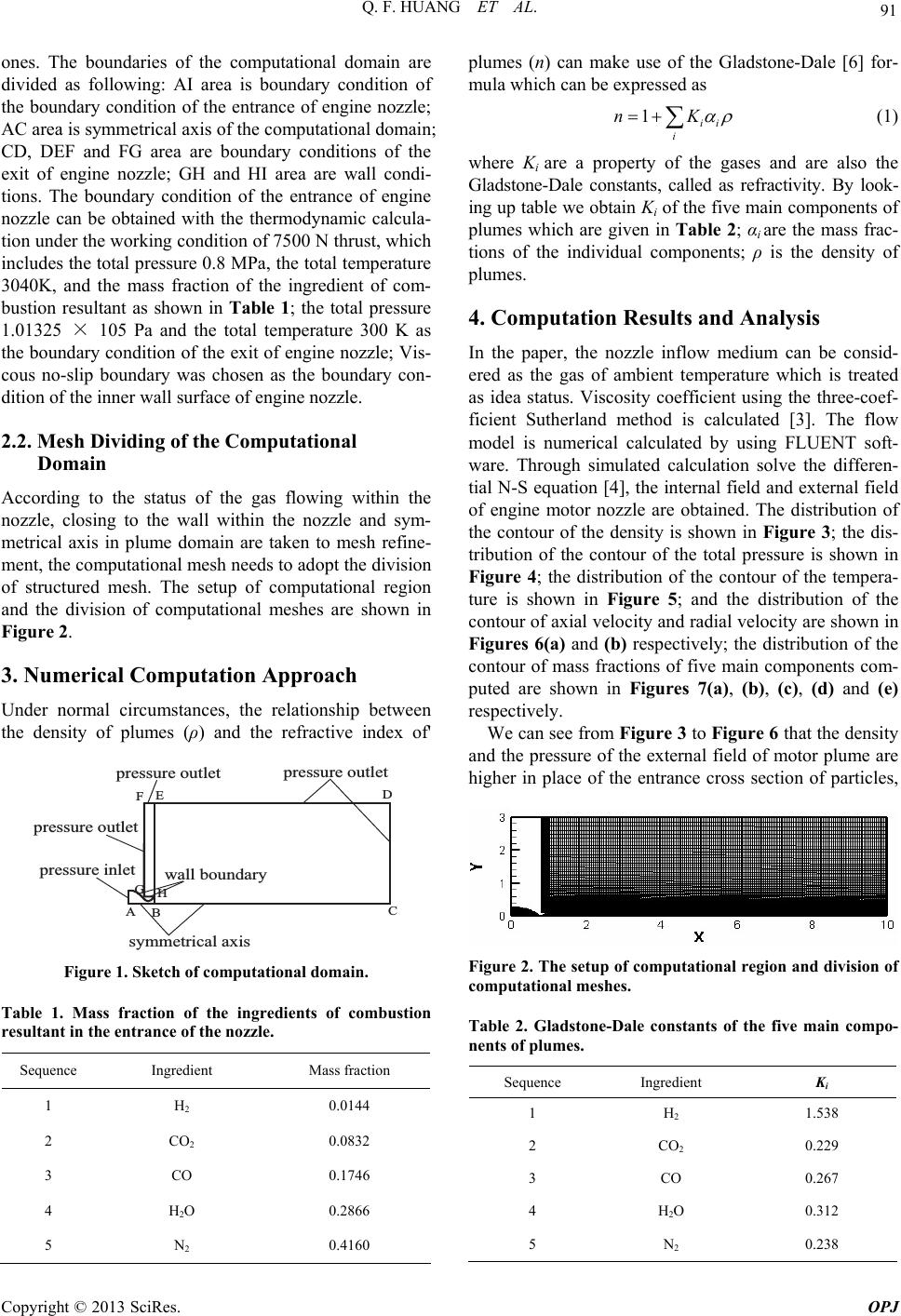 Q. F. HUANG ET AL. 91 ones. The boundaries of the computational domain are divided as following: AI area is boundary condition of the boundary condition of the entrance of engine nozzle; AC area is symmetrical axis of the computational domain; CD, DEF and FG area are boundary conditions of the exit of engine nozzle; GH and HI area are wall condi- tions. The boundary condition of the entrance of engine nozzle can be obtained with the thermodynamic calcula- tion under the working conditio n of 75 00 N thru st, which includes the total pressure 0.8 MPa, the total temperature 3040K, and the mass fraction of the ingredient of com- bustion resultant as shown in Table 1; the total pressure 1.01325 × 10⁵ Pa and the total temperature 300 K as the boundary condition of the exit of engine nozzle; Vis- cous no-slip boundary was chosen as the boundary con- dition of the inner wall surface of engine nozzle. 2.2. Mesh Dividing of the Computational Domain According to the status of the gas flowing within the nozzle, closing to the wall within the nozzle and sym- metrical axis in plume domain are taken to mesh refine- ment, the computational mesh needs to adopt the division of structured mesh. The setup of computational region and the division of computational meshes are shown in Figure 2. 3. Numerical Computation Approach Under normal circumstances, the relationship between the density of plumes (ρ) and the refractive index of' =>7??A>7 <A@97@=>7??A>7 <A@97@ =>7??A>7 <A@97@ =>7??A>7 8;97@B399 4<A;63>D ?D::7@>8539 3C8? 0/. - , + 12 Figure 1. Sketch of computational domain. Table 1. Mass fraction of the ingredients of combustion resultant in the entrance of the nozzle. Sequence Ingredient Mass fraction 1 H2 0.0144 2 CO2 0.0832 3 CO 0.1746 4 H2O 0.2866 5 N2 0.4160 plumes (n) can make use of the Gladstone-Dale [6] for- mula which can be expressed as 1ii i nK (1) where Ki are a property of the gases and are also the Gladstone-Dale constants, called as refractivity. By look- ing up table we obtain Ki of the five main components of plumes which are given in Table 2; αi are the mass frac- tions of the individual components; ρ is the density of plumes. 4. Computation Results and Analysis In the paper, the nozzle inflow medium can be consid- ered as the gas of ambient temperature which is treated as idea status. Viscosity coefficient using the three-coef- ficient Sutherland method is calculated [3]. The flow model is numerical calculated by using FLUENT soft- ware. Through simulated calculation solve the differen- tial N-S equation [4], the internal field and external field of engine motor nozzle are obtained. The distribution of the contour of the density is shown in Figure 3; the dis- tribution of the contour of the total pressure is shown in Figure 4; the distribution of the contour of the tempera- ture is shown in Figure 5; and the distribution of the contour of axial velocity and radial velocity are shown in Figures 6(a) and (b) respectively; the distribution of the contour of mass fractions of five main components com- puted are shown in Figures 7(a), (b), (c), (d) and (e) respectively. We can see from Figure 3 to Figure 6 that the density and the pressure of the external field of motor plume are higher in place of the entrance cross section of particles, Figure 2. The setup of computational region and division of computational meshes. Table 2. Gladstone-Dale constants of the five main compo- nents of plumes. Sequence Ingredient Ki 1 H2 1.538 2 CO2 0.229 3 CO 0.267 4 H2O 0.312 5 N2 0.238 Copyright © 2013 SciRes. OPJ 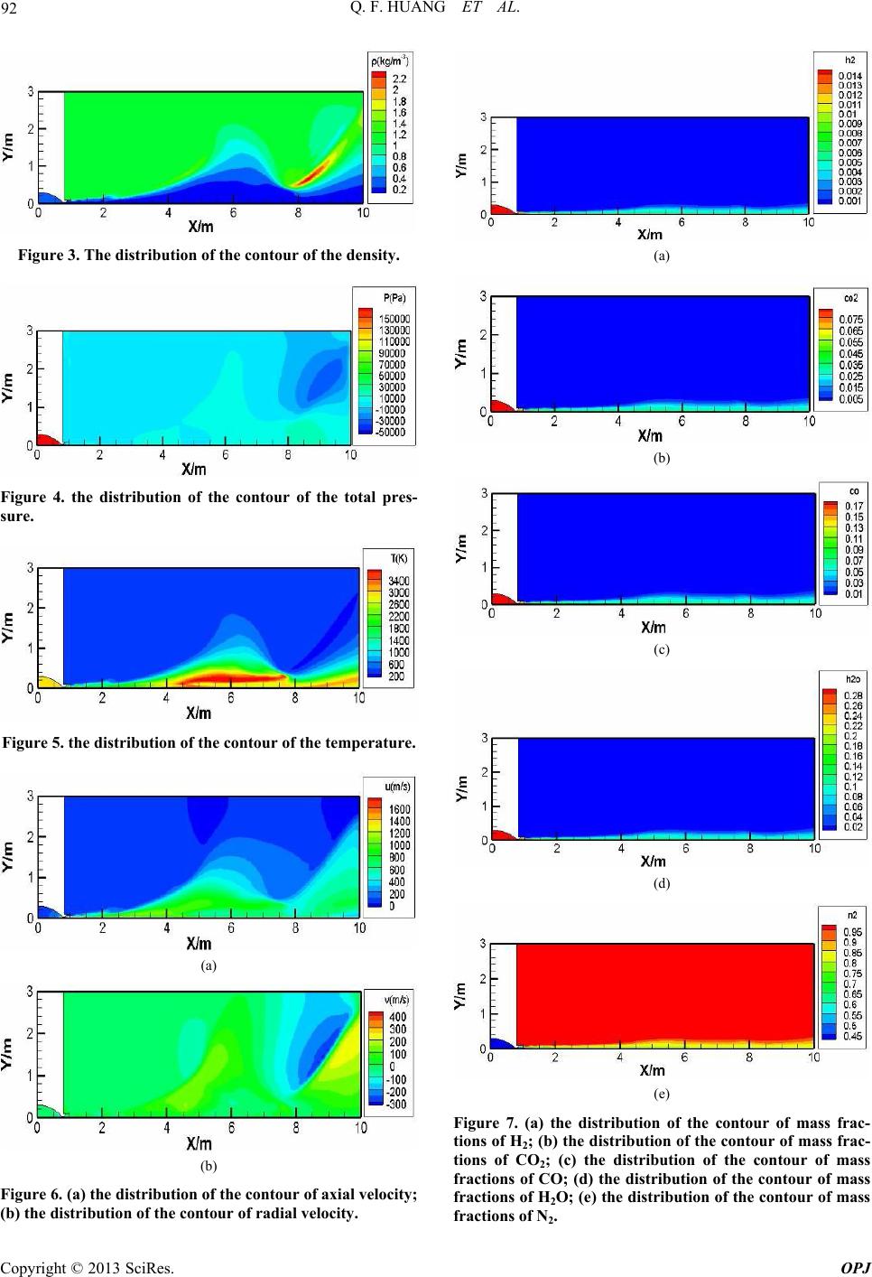 Q. F. HUANG ET AL. 92 Figure 3. The distribution of the contour of the density. Figure 4. the distribution of the contour of the total pres- sure. Figure 5. the distribution of the contour of the temperature. (a) (b) Figure 6. (a) the distribution of the contour of axial velocity; (b) the distribution of the contour of radial velocity. (a) (b) (c) (d) (e) Figure 7. (a) the distribution of the contour of mass frac- tions of H2; (b) the distribution of the contour of mass frac- tions of CO2; (c) the distribution of the contour of mass fractions of CO; (d) the distribution of the contour of mass fractions of H2O; (e) the distribution of the contour of mass fractions of N2. Copyright © 2013 SciRes. OPJ  Q. F. HUANG ET AL. Copyright © 2013 SciRes. OPJ 93 but reduced with air stream flowing to the vacuum; the higher the temperature, the faster the particle’s velocity, and with the expansion of jet flow and continue to rise, temperature does not rise after gas flow diffuse into the plume field; the axial velo city is the smallest o ne through the exit cross section of motor, but radial velocity is the biggest one, basically the distribution of velocity along radial direction and increase constantly, and show a dif- fusing accelerated process. We can see from Figure 7 that the mass fractions of the five individual components are changed constantly with gases flowing into motor plume. The above analysis shows that the main impact in the motor plume flow field is that come from the diffusion of boundary layer in the exit wall boundary of motor; plume in vacuum diffuses very fast, and the ability of doing work decrease greatly; the refractive index field will have an influence with gas flow di ffusion. 5. Conclusions This paper mainly calculated the refractive index field of rocket motor nozzle plume, and two-dimensional axi- symmetric Reynolds averaged NS equation was chosen to solve; this paper that using FLUENT software carried out numerical simulation which analyzed detailed condi- tions and distribution characteristics of internal field and external field of nozzle. At the same time, related fluid flow theory was verified. This simulation provided the data base in aspects of the design of rocket motor and carrying out other researches for plume flow field. Other parts need to be further study. 6. Acknowledgements The work was supported by Chinese Natural Science Foundation (grant 61271397), Jiangxi provincial Natural Science Foundation (grant 20122BAB202009), Jiangxi provincial education department Science and Technology Foundation (grant GJJ12408) and preferentially funded by the “Hundred Talents Plan” of the Chinese Academy of Sciences. REFERENCES [1] V. Yakhot and S. A. Orszag, “Renormalizationg Roup Analysis of Turbulence-I: Basic Theory,” Scientific Com- puting, Vol.1, 1986, pp. 1- 51. [2] G. J. Zu, et al., “N-S Numerical Simulation of the Nozzle Flow Field and Plume,”Journal of Propulsion Technology, Vol. 16, No. 5, 1995. [3] J. Liu, et al., “Numerical Simulation on Flow Field of Double Nozzle Solid Rocket Motors,” Journal of Solid Rocket Technology, Vol. 25, No. 1, 2002. [4] J. X. Zhao, “Numerical Simulation of Combustion,” Sci- ence Press, Beijing, 2002. [5] Y. Y. Chen, Z. H. Li, Y. Song and A. Z. He, “Extension of the Gladstone-Dale Equation for Flame Flow Field Diagnosis by Optical Computerized Tomography,” Ap- plied Optics, Vol. 48, 2009, pp. 2485-2490. doi:10.1364/AO.48.002485 [6] C. M. Vest, “Holographic Interferometry John Wiley,” New York, 1979. |