

Paper Menu >>
Journal Menu >>
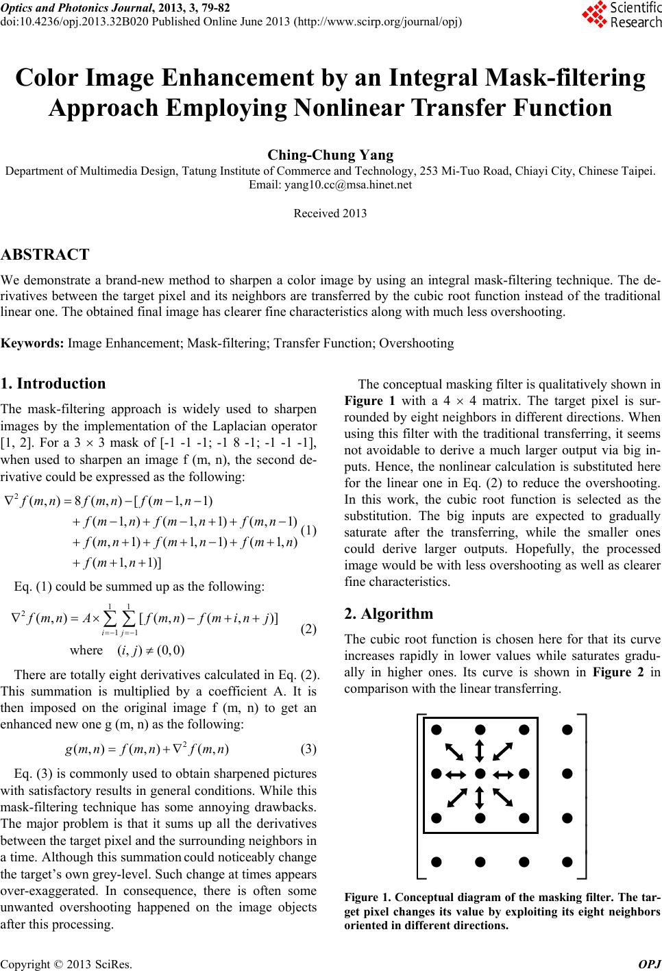 Optics and Photonics Journal, 2013, 3, 79-82 doi:10.4236/opj.2013.32B020 Published Online June 2013 (http://www.scirp.org/journal/opj) Color Image Enhancement by an Integral Mask-filtering Approach Employing Nonlinear Transfer Function Ching-Chung Yang Department of Multimedia Design, Tatung Institute of Commerce and Technology, 253 Mi-Tuo Road, Chiayi City, Chinese Taipei. Email: [email protected] Received 2013 ABSTRACT We demonstrate a brand-new method to sharpen a color image by using an integral mask-filtering technique. The de- rivatives between the target pixel and its neighbors are transferred by the cubic root function instead of the traditional linear one. The obtained final image has clearer fine characteristics along with much less overshooting. Keywords: Image Enhancement; Mask-filtering; Transfer Function; Overshooting 1. Introduction The mask-filtering approach is widely used to sharpen images by the implementation of the Laplacian operator [1, 2]. For a 3 3 mask of [-1 -1 -1; -1 8 -1; -1 -1 -1], when used to sharpen an image f (m, n), the second de- rivative could be expressed as the following: 2(,) 8(,)[(1,1) (1,)(1,1)(,1) (,1)(1,1)(1,) (1,1)] fmnfmnfm n fm nfm nfmn f mnf mnf mn fm n (1) Eq. (1) could be summed up as th e following: 11 2 11 (,)[(,) (,)] where (,)(0,0) ij f mnAf mnfminj ij (2) There are totally eight d erivatives calculated in Eq. (2). This summation is multiplied by a coefficient A. It is then imposed on the original image f (m, n) to get an enhanced new one g (m, n) as the following: 2 (,) (,)(,) g mnf mnf mn (3) Eq. (3) is commonly used to obtain sharpened pictures with satisfactory results in general conditions. While this mask-filtering technique has some annoying drawbacks. The major problem is that it sums up all the derivatives between the targ et pixe l and th e su rro und ing ne ighbor s in a time. Although this summation could no ticeably change the target’s own grey-level. Such change at times appears over-exaggerated. In consequence, there is often some unwanted overshooting happened on the image objects after this processing. The conceptual masking filter is qualitatively shown in Figure 1 with a 4 4 matrix. The target pixel is sur- rounded by eight neighbors in different directions. When using this filter with the traditional transferring, it seems not avoidable to derive a much larger output via big in- puts. Hence, the nonlinear calculation is substituted here for the linear one in Eq. (2) to reduce the overshooting. In this work, the cubic root function is selected as the substitution. The big inputs are expected to gradually saturate after the transferring, while the smaller ones could derive larger outputs. Hopefully, the processed image would be with less overshooting as well as clearer fine characteristics. 2. Algorithm The cubic root function is chosen here for that its curve increases rapidly in lower values while saturates gradu- ally in higher ones. Its curve is shown in Figure 2 in comparison with the linear transferring. Figure 1. Conceptual diagram of the ma sking filter. The tar- get pixel changes its value by exploiting its eight neighbors oriented in different directions. Copyright © 2013 SciRes. OPJ 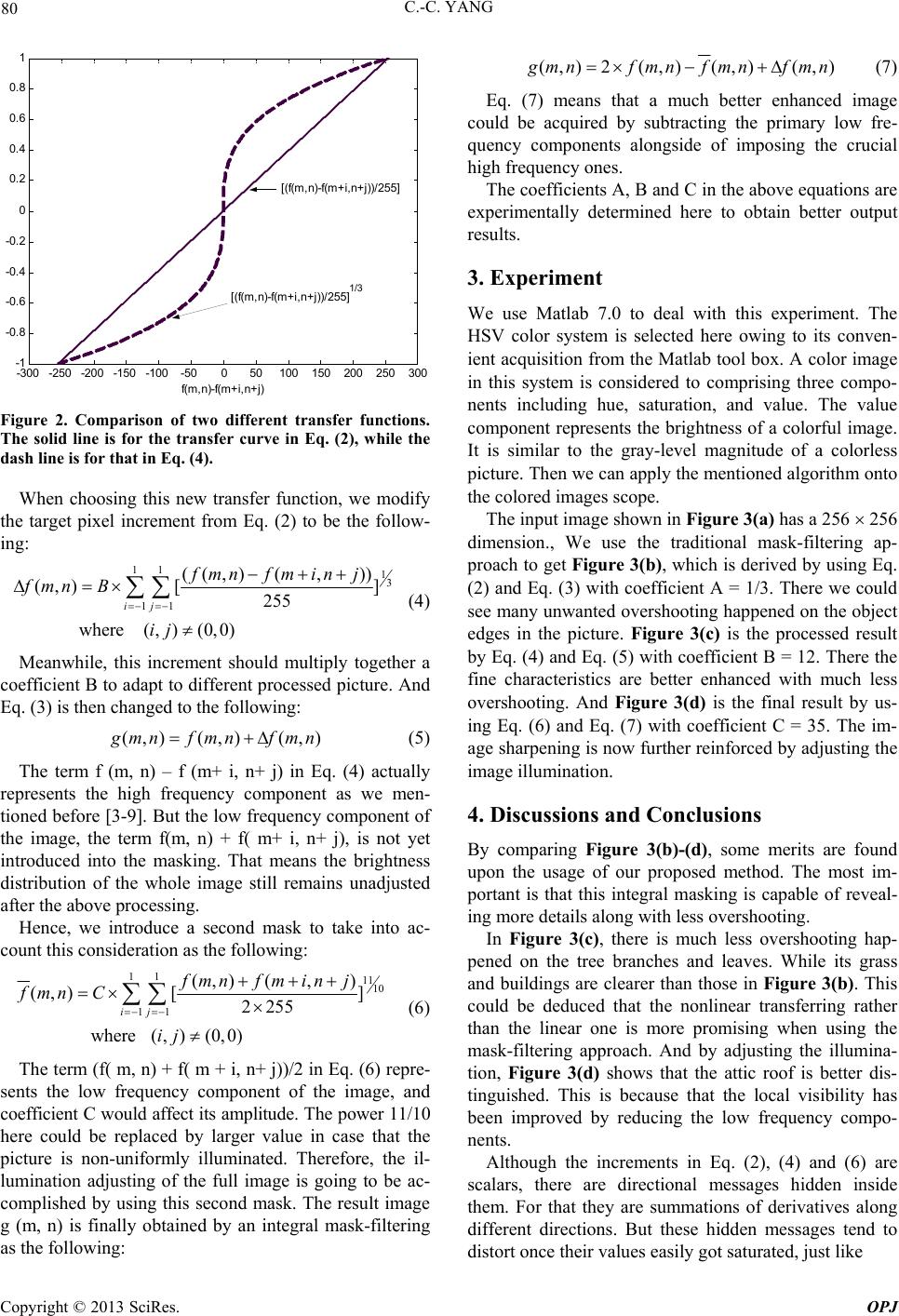 C.-C. YANG 80 -300 -250 -200 -150 -100-50 050100 150 200 250 300 -1 -0. 8 -0. 6 -0. 4 -0. 2 0 0. 2 0. 4 0. 6 0. 8 1 f(m,n)-f(m+i,n+j) [ (f(m ,n)-f(m+i,n+j))/2 55] [ (f(m ,n)-f(m+i,n+j))/255 ] 1/3 Figure 2. Comparison of two different transfer functions. The solid line is for the transfer curve in Eq. (2), while the dash line is for that in Eq. (4). When choosing this new transfer function, we modify the target pixel increment from Eq. (2) to be the follow- ing: 11 13 11 ((,) (,)) (,) [] 255 where (,)(0,0) ij fmnfm inj fmn B ij (4) Meanwhile, this increment should multiply together a coefficient B to adapt to different processed picture. And Eq. (3) is then changed to the following: (,) (,)(,) g mnf mnfmn (5) The term f (m, n) – f (m+ i, n+ j) in Eq. (4) actually represents the high frequency component as we men- tioned before [3-9]. But the low frequency component of the image, the term f(m, n) + f( m+ i, n+ j), is not yet introduced into the masking. That means the brightness distribution of the whole image still remains unadjusted after th e above pro cessing. Hence, we introduce a second mask to take into ac- count this consideration as the following: 11 1110 11 (,) (,) (,) [] 2255 where (,)(0,0) ij fmnfm inj fmn C ij (6) The term (f( m, n) + f( m + i, n+ j))/2 in Eq. (6) repre- sents the low frequency component of the image, and coefficient C would affect its amplitude. The power 11/10 here could be replaced by larger value in case that the picture is non-uniformly illuminated. Therefore, the il- lumination adjusting of the full image is going to be ac- complished by using this second mask. The result image g (m, n) is finally obtained by an integral mask-filtering as the following: (,) 2(,)(,)(,) g mnf mnfmnfmn (7) Eq. (7) means that a much better enhanced image could be acquired by subtracting the primary low fre- quency components alongside of imposing the crucial high frequency ones. The coefficients A, B and C in the above equ ations a re experimentally determined here to obtain better output results. 3. Experiment We use Matlab 7.0 to deal with this experiment. The HSV color system is selected here owing to its conven- ient acquisition from the Matlab to ol box. A color image in this system is considered to comprising three compo- nents including hue, saturation, and value. The value component represents the brightness of a colorful image. It is similar to the gray-level magnitude of a colorless picture. Then we can apply the mentioned algorithm onto the colored images scope. The input image shown in Figure 3(a) has a 256 256 dimension., We use the traditional mask-filtering ap- proach to get Figure 3(b), which is derived by using Eq. (2) and Eq. (3) with coefficient A = 1/3. There we could see many unwanted overshooting happened on the object edges in the picture. Figure 3(c) is the processed result by Eq. (4) and Eq. (5) with coefficient B = 12. There the fine characteristics are better enhanced with much less overshooting. And Figure 3(d) is the final result by us- ing Eq. (6) and Eq. (7) with coefficient C = 35. The im- age sharpening is now further reinforced by adjusting the image illumination. 4. Discussions and Conclusions By comparing Figure 3(b)-(d), some merits are found upon the usage of our proposed method. The most im- portant is that this integral masking is capable of reveal- ing more details along with less overshooting . In Figure 3(c), there is much less overshooting hap- pened on the tree branches and leaves. While its grass and buildings are clearer than those in Figure 3(b). This could be deduced that the nonlinear transferring rather than the linear one is more promising when using the mask-filtering approach. And by adjusting the illumina- tion, Figure 3(d) shows that the attic roof is better dis- tinguished. This is because that the local visibility has been improved by reducing the low frequency compo- nents. Although the increments in Eq. (2), (4) and (6) are scalars, there are directional messages hidden inside them. For that they are summations of derivatives along different directions. But these hidden messages tend to distort once their values easily got saturated, just like Copyright © 2013 SciRes. OPJ 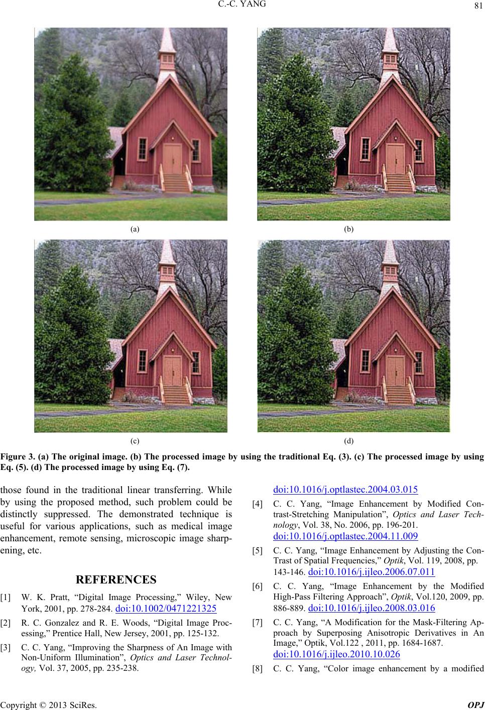 C.-C. YANG Copyright © 2013 SciRes. OPJ 81 (a) (b) (c) (d) Figure 3. (a) The original image. (b) The processed image by using the traditional Eq. (3). (c) The processed image by using Eq. (5). (d) The processed image by using Eq. (7). those found in the traditional linear transferring. While by using the proposed method, such problem could be distinctly suppressed. The demonstrated technique is useful for various applications, such as medical image enhancement, remote sensing, microscopic image sharp- ening, etc. REFERENCES [1] W. K. Pratt, “Digital Image Processing,” Wiley, New York, 2001, pp. 278-284. doi:10.1002/0471221325 [2] R. C. Gonzalez and R. E. Woods, “Digital Image Proc- essing,” Prentice Hall, New Jersey, 2001, pp. 125-132. [3] C. C. Yang, “Improving the Sharpness of An Image with Non-Uniform Illumination”, Optics and Laser Technol- ogy, Vol. 37, 2005, pp. 235-238. doi:10.1016/j.optlastec.2004.03.015 [4] C. C. Yang, “Image Enhancement by Modified Con- trast-Stretching Manipulation”, Optics and Laser Tech- nology, Vol. 38, No. 2006, pp. 196-201. doi:10.1016/j.optlastec.2004.11.009 [5] C. C. Yang, “Image Enhancement by Adjusting the Con- Trast of Spatial Frequencies,” Optik, Vol. 119, 2008, pp. 143-146. doi:10.1016/j.ijleo.2006.07.011 [6] C. C. Yang, “Image Enhancement by the Modified High-Pass Filtering Approach”, Optik, Vol.120, 2009, pp. 886-889. doi:10.1016/j.ijleo.2008.03.016 [7] C. C. Yang, “A Modification for the Mask-Filtering Ap- proach by Superposing Anisotropic Derivatives in An Image,” Optik, Vol.122 , 2011, pp. 16 84-1687. doi:10.1016/j.ijleo.2010.10.026 [8] C. C. Yang, “Color image enhancement by a modified  C.-C. YANG 82 mask-filteringapproach,” Optik, Vol. 123, 2012, pp. 1765-1767. doi:10.1016/j.ijleo.2011.11.057 [ 9] C. C. Yang, “Improving the Overshooting of A Sharp- ened Image by Employing Nonlinear Transfer Functions in the Mask-Filtering Approach,” Optik, in press. Copyright © 2013 SciRes. OPJ |