

Paper Menu >>
Journal Menu >>
 Optics and Photonics Journal, 2013, 3, 66-68 doi:10.4236/opj.2013.32B016 Published Online June 2013 (http://www.scirp.org/journal/opj) Four-wavelength Microdisk Lasers Laterally Coupling to an Output Bus Waveguide Ling-Xiu Zou, Xiao-Meng Lv, Yong-Zhen Huang, Heng Long, Qi-Feng Yao, Yun Du The State Key Laboratory on Integrated Optoelectronics, Institute of Semiconductors, Chinese Academy of Sciences, Beijing, China Email: [email protected] Received 2013 ABSTRACT A multiple-wavelength GaInAsP/InP microlaser with microdisk radiuses from 10 m to 10.6 m laterally coupled into a bus waveguide are fabricated by standard photolithygraphy and inductively coupled-plasma (ICP) etching techniques. The lasing wavelengths are 1533 nm, 1541 nm, 1551 nm and 1555 nm at the CW injection current of 10 mA for the four microlasers. The proposed multiple-microlaser array would be useful for realizing compact wavelength division multiplexing (WDM) light source for optical interconnects. Keywords: Optical Resonator; Microdisk Laser; Laser Arrays 1. Introduction Optical wavelength division multiplexing (WDM) tech- nology has attracted great attentions for noticeably in- creasing the bandwidth density and communication ca- pacity of a single link and makes it more feasible to real- ize monolithic PICs. To meet the increasing requirement of optical interconnection link, laser sources which could emit signals of several wavelengths with equal intervals are indispensable [1]. This sort of multi-wavelength laser (MWL) source can be realized by cascading several mi- crolasers on one SOI bus waveguide as shown in [2]. As microdisk lasers have long been proposed as attractive light sources for integrated optical circuits due to their high Q-factors, low power consumption and cleavage- free lasing cavities [3,4], multi-wavelength operation has also been demonstrated by vertically coupling the WG mode laser from microdisk cavities with different radi- uses into a bus I/O waveguide [5-7]. However, the fabri- cation of this kind of microdisk lasers has been highly limited to the complexity of multi-layer growth process or bonding technology. In this paper, we proposed a sim- ple but efficient way to coupling the light out of the mi- crocavity using laterally coupling method, and the com- pact integration of four-wavelength microdisk lasers to a single bus waveguide is also realized. In this paper, we will introduce the fabrication process of four-wavelengths microdisk lasers laterally coupling to a bus waveguide, the voltage and output power inten- sity versus the injection current are both measured and discussed. Finally, the lasing spectra of four microlasers at the same injection current of 10 mA are given and compared. 2. Design and Fabrication When adjacent microdisk modes, with different radial distributions or azimuthal mode numbers, are not spec- trally remote enough from one another, and both compa- rably close to gain peak wavelength, these modes are very likely to be involved in a competition process to acquire gain that results in lasing mode hopping over a range of currents. To avoid this situation, adjacent modes should be separated by diverse free spectral range (FSR), which can be achieved by design different disk sizes. In this paper, we demonstrate four-wavelength microdisk lasers consist of four microdisk cavities and one 2-m- width bus waveguide, with the radiuses of four cavities regularly ranging from 10 m to 10.6 m. The free spec- tral ranges (FSR) of the cavity resonance are about 11 nm - 12 nm in this case. An AlGaInAs/InP laser wafer grown by metal-organic chemical vapor deposition (MOCVD) is used for fabri- cating the devices. The active region of the laser wafer consists of six compressively strained 6-nm-thick Al0.24 GaIn0.71As quantum wells and 9-nm-thick Al0.44GaIn0.49As barrier layers. The total growth thickness is roughly 2.3 nm without the N-InP buffer layer. The fabrication proc- esses can be briefly summarized as follows. *This work was supported by High Technology Development Project under Grant 2012AA012202, and the National Nature Science Founda- tion of China under Grants 61235004, 61006042, 61106048, and 61061160502. First, an 800-nm SiO2 layer was deposited by plasma- Copyright © 2013 SciRes. OPJ 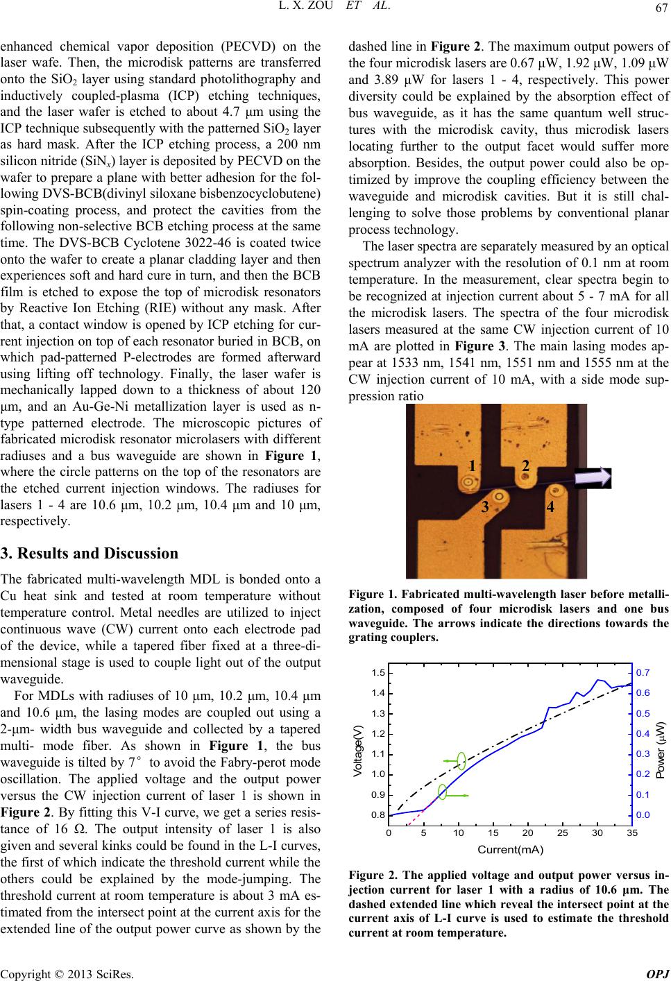 L. X. ZOU ET AL. 67 enhanced chemical vapor deposition (PECVD) on the laser wafe. Then, the microdisk patterns are transferred onto the SiO2 layer using standard photolithography and inductively coupled-plasma (ICP) etching techniques, and the laser wafer is etched to about 4.7 μm using the ICP technique subsequently with the patterned SiO2 layer as hard mask. After the ICP etching process, a 200 nm silicon nitride (SiNx) layer is deposited by PECVD on the wafer to prepare a plane with better adhesion for the fol- lowing DVS-BCB(divinyl siloxane bisbenzocyclobutene) spin-coating process, and protect the cavities from the following non-selective BCB etching process at the same time. The DVS-BCB Cyclotene 3022-46 is coated twice onto the wafer to create a planar cladding layer and then experiences soft and hard cure in turn, and then the BCB film is etched to expose the top of microdisk resonators by Reactive Ion Etching (RIE) without any mask. After that, a contact window is opened by ICP etching for cur- rent injection on top of each resonator buried in BCB, on which pad-patterned P-electrodes are formed afterward using lifting off technology. Finally, the laser wafer is mechanically lapped down to a thickness of about 120 μm, and an Au-Ge-Ni metallization layer is used as n- type patterned electrode. The microscopic pictures of fabricated microdisk resonator microlasers with different radiuses and a bus waveguide are shown in Figure 1, where the circle patterns on the top of the resonators are the etched current injection windows. The radiuses for lasers 1 - 4 are 10.6 μm, 10.2 μm, 10.4 μm and 10 μm, respectively. 3. Results and Discussion The fabricated multi-wavelength MDL is bonded onto a Cu heat sink and tested at room temperature without temperature control. Metal needles are utilized to inject continuous wave (CW) current onto each electrode pad of the device, while a tapered fiber fixed at a three-di- mensional stage is used to couple light out of the output waveguide. For MDLs with radiuses of 10 μm, 10.2 μm, 10.4 μm and 10.6 μm, the lasing modes are coupled out using a 2-μm- width bus waveguide and collected by a tapered multi- mode fiber. As shown in Figure 1, the bus waveguide is tilted by 7°to avoid the Fabry-perot mode oscillation. The applied voltage and the output power versus the CW injection current of laser 1 is shown in Figure 2. By fitting this V-I curve, we get a series resis- tance of 16 Ω. The output intensity of laser 1 is also given and several kinks could be found in the L-I curves, the first of which indicate the threshold current while the others could be explained by the mode-jumping. The threshold current at room temperature is about 3 mA es- timated from the intersect point at the current axis for the extended line of the output power curve as shown by the dashed line in Figure 2. The maximum output powers of the four microdisk lasers are 0.67 μW, 1.92 μW, 1.09 μW and 3.89 μW for lasers 1 - 4, respectively. This power diversity could be explained by the absorption effect of bus waveguide, as it has the same quantum well struc- tures with the microdisk cavity, thus microdisk lasers locating further to the output facet would suffer more absorption. Besides, the output power could also be op- timized by improve the coupling efficiency between the waveguide and microdisk cavities. But it is still chal- lenging to solve those problems by conventional planar process technology. The laser spectra are separately measured by an optical spectrum analyzer with the resolution of 0.1 nm at room temperature. In the measurement, clear spectra begin to be recognized at injection current about 5 - 7 mA for all the microdisk lasers. The spectra of the four microdisk lasers measured at the same CW injection current of 10 mA are plotted in Figure 3. The main lasing modes ap- pear at 1533 nm, 1541 nm, 1551 nm and 1555 nm at the CW injection current of 10 mA, with a side mode sup- pression ratio 12 34 Figure 1. Fabricated multi-wavelength laser before metalli- zation, composed of four microdisk lasers and one bus waveguide. The arrows indicate the directions towards the grating couplers. 0510 15 20 25 30 35 0.8 0.9 1.0 1.1 1.2 1.3 1.4 1.5 Current(mA) Voltage(V) 0.0 0.1 0.2 0.3 0.4 0.5 0.6 0.7 Power ( W) Figure 2. The applied voltage and output power versus in- jection current for laser 1 with a radius of 10.6 μm. The dashed extended line which reveal the intersect point at the current axis of L-I curve is used to estimate the threshold current at room temperature. Copyright © 2013 SciRes. OPJ 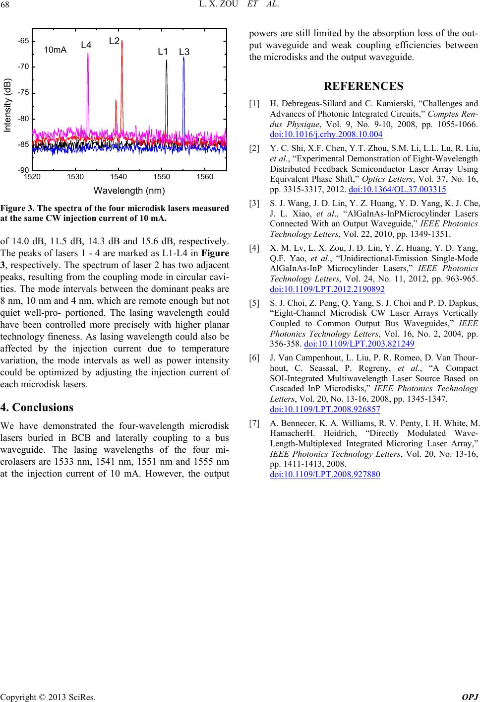 L. X. ZOU ET AL. Copyright © 2013 SciRes. OPJ 68 1520 1530 1540 1550 1560 -90 -85 -80 -75 -70 -65 Intensity (d B) Wavelength (nm) L1 L2 L3 L4 10mA Figure 3. The spectra of the four microdisk lasers measured at the same CW injection current of 10 mA. of 14.0 dB, 11.5 dB, 14.3 dB and 15.6 dB, respectively. The peaks of lasers 1 - 4 are marked as L1-L4 in Figure 3, respectively. The spectrum of laser 2 has two adjacent peaks, resulting from the coupling mode in circular cavi- ties. The mode intervals between the dominant peaks are 8 nm, 10 nm and 4 nm, which are remote enough but not quiet well-pro- portioned. The lasing wavelength could have been controlled more precisely with higher planar technology fineness. As lasing wavelength could also be affected by the injection current due to temperature variation, the mode intervals as well as power intensity could be optimized by adjusting the injection current of each microdisk lasers. 4. Conclusions We have demonstrated the four-wavelength microdisk lasers buried in BCB and laterally coupling to a bus waveguide. The lasing wavelengths of the four mi- crolasers are 1533 nm, 1541 nm, 1551 nm and 1555 nm at the injection current of 10 mA. However, the output powers are still limited by the absorption loss of the out- put waveguide and weak coupling efficiencies between the microdisks and the output waveguide. REFERENCES [1] H. Debregeas-Sillard and C. Kamierski, “Challenges and Advances of Photonic Integrated Circuits,” Comptes Ren- dus Physique, Vol. 9, No. 9-10, 2008, pp. 1055-1066. doi:10.1016/j.crhy.2008.10.004 [2] Y. C. Shi, X.F. Chen, Y.T. Zhou, S.M. Li, L.L. Lu, R. Liu, et al., “Experimental Demonstration of Eight-Wavelength Distributed Feedback Semiconductor Laser Array Using Equivalent Phase Shift,” Optics Letters, Vol. 37, No. 16, pp. 3315-3317, 2012. doi:10.1364/OL.37.003315 [3] S. J. Wang, J. D. Lin, Y. Z. Huang, Y. D. Yang, K. J. Che, J. L. Xiao, et al., “AlGaInAs-InPMicrocylinder Lasers Connected With an Output Waveguide,” IEEE Photonics Technology Letters, Vol. 22, 2010, pp. 1349-1351. [4] X. M. Lv, L. X. Zou, J. D. Lin, Y. Z. Huang, Y. D. Yang, Q.F. Yao, et al., “Unidirectional-Emission Single-Mode AlGaInAs-InP Microcylinder Lasers,” IEEE Photonics Technology Letters, Vol. 24, No. 11, 2012, pp. 963-965. doi:10.1109/LPT.2012.2190892 [5] S. J. Choi, Z. Peng, Q. Yang, S. J. Choi and P. D. Dapkus, “Eight-Channel Microdisk CW Laser Arrays Vertically Coupled to Common Output Bus Waveguides,” IEEE Photonics Technology Letters, Vol. 16, No. 2, 2004, pp. 356-358. doi:10.1109/LPT.2003.821249 [6] J. Van Campenhout, L. Liu, P. R. Romeo, D. Van Thour- hout, C. Seassal, P. Regreny, et al., “A Compact SOI-Integrated Multiwavelength Laser Source Based on Cascaded InP Microdisks,” IEEE Photonics Technology Letters, Vol. 20, No. 13-16, 2008, pp. 1345-1347. doi:10.1109/LPT.2008.926857 [7] A. Bennecer, K. A. Williams, R. V. Penty, I. H. White, M. HamacherH. Heidrich, “Directly Modulated Wave- Length-Multiplexed Integrated Microring Laser Array,” IEEE Photonics Technology Letters, Vol. 20, No. 13-16, pp. 1411-1413, 2008. doi:10.1109/LPT.2008.927880 |