

Paper Menu >>
Journal Menu >>
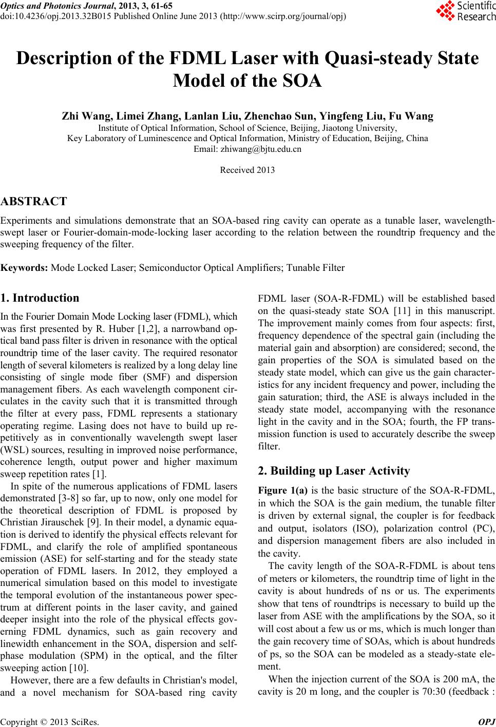 Optics and Photonics Journal, 2013, 3, 61-65 doi:10.4236/opj.2013.32B015 Published Online June 2013 (http://www.scirp.org/journal/opj) Description of the FDML Laser with Quasi-steady State Model of the SOA Zhi Wang, Limei Zhang, Lanlan Liu, Zhenchao Sun, Yingfeng Liu, Fu Wang Institute of Optical Information, School of Science, Beijing, Jiaotong University, Key Laboratory of Luminescence and Optical Information, Ministry of Education, Beijing, China Email: [email protected] Received 2013 ABSTRACT Experiments and simulations demonstrate that an SOA-based ring cavity can operate as a tunable laser, wavelength- swept laser or Fourier-domain-mode-locking laser according to the relation between the roundtrip frequency and the sweeping frequency of the filter. Keywords: Mode Locked Laser; Semiconductor Optical Amplifiers; Tunable Filter 1. Introduction In the Fourier Domain Mode Locking laser (FD ML), which was first presented by R. Huber [1,2], a narrowband op- tical band pass filter is driven in resonance with the optical roundtrip time of the laser cavity. The required resonator length of several kilometers is realized by a long delay line consisting of single mode fiber (SMF) and dispersion management fibers. As each wavelength component cir- culates in the cavity such that it is transmitted through the filter at every pass, FDML represents a stationary operating regime. Lasing does not have to build up re- petitively as in conventionally wavelength swept laser (WSL) sources, resulting in improved noise performance, coherence length, output power and higher maximum sweep repetition rates [1]. In spite of the numerous applications of FDML lasers demonstrated [3-8] so far, up to now, only one model f or the theoretical description of FDML is proposed by Christian Jirauschek [9]. In their model, a dynamic equa- tion is derived to identify the physical effects relevant for FDML, and clarify the role of amplified spontaneous emission (ASE) for self-starting and for the steady state operation of FDML lasers. In 2012, they employed a numerical simulation based on this model to investigate the temporal evolution of the instantaneous power spec- trum at different points in the laser cavity, and gained deeper insight into the role of the physical effects gov- erning FDML dynamics, such as gain recovery and linewidth enhancement in the SOA, dispersion and self- phase modulation (SPM) in the optical, and the filter sweeping action [10]. However, there are a few defaults in Christian's model, and a novel mechanism for SOA-based ring cavity FDML laser (SOA-R-FDML) will be established based on the quasi-steady state SOA [11] in this manuscript. The improvement mainly comes from four aspects: first, frequency dependence of the spectral gain (including the material gain and absorption) are considered; second, the gain properties of the SOA is simulated based on the steady state model, which can give us the gain character- istics for any incident frequency and power, including the gain saturation; third, the ASE is always included in the steady state model, accompanying with the resonance light in the cavity and in the SOA; fourth, the FP trans- mission function is used to accurately describe the sweep filter. 2. Building up Laser Activity Figure 1(a) is the basic structure of the SOA-R-FDML, in which the SOA is the gain medium, the tunable filter is driven by external signal, the coupler is for feedback and output, isolators (ISO), polarization control (PC), and dispersion management fibers are also included in the cavity. The cavity length of the SOA-R-FDML is about tens of meters or kilometers, the roundtrip time of light in the cavity is about hundreds of ns or us. The experiments show that tens of roundtrips is necessary to build up the laser from ASE with the amplifications by the SOA, so it will cost about a few us or ms, which is much longer than the gain recovery time of SOAs, which is abou t hundreds of ps, so the SOA can be modeled as a steady-state ele- ment. When the injection curren t of the SOA is 200 mA, the cavity is 20 m long, and the coupler is 70:30 (feedback : Copyright © 2013 SciRes. OPJ 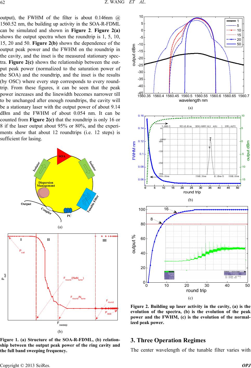 Z. WANG ET AL. 62 output), the FWHM of the filter is about 0.146nm @ 1560.52 nm, the building up activity in the SOA-R-FDML can be simulated and shown in Figure 2. Figure 2(a) shows the output spectra when the roundtrip is 1, 5, 10, 15, 20 and 50. Figure 2(b) shows the dependence of the output peak power and the FWHM on the roundtrip in the cavity, and the inset is the measured stationary spec- tra. Figure 2(c) shows the relationship between the out- put peak power (normalized to the saturation power of the SOA) and the roundtrip, and the inset is the results (by OSC) where every step corresponds to every round- trip. From these figures, it can be seen that the peak power increases and the linewidth becomes narrower till to be unchanged after enough roundtrips, the cavity will be a stationary laser with the output power of about 9.14 dBm and the FWHM of about 0.054 nm. It can be counted from Figure 2(c) that the roundtrip is only 16 or 8 if the laser output about 95% or 80%, and the experi- ments show that about 12 roundtrips (i.e. 12 steps) is sufficient for lasing. (a) F sweep P out II III F round /N tu n e F round /(NxN tune ) F round P sat I P ASE (b) Figure 1. (a) Structure of the SOA-R-FDML, (b) relation- ship between the output peak power of the ring cavity and the full band sweeping frequency. 1560.351560.41560.451560.51560.551560.61560.651560.7 -45 -40 -35 -30 -25 -20 -15 -10 -5 0 5 10 wa v elength nm output dB m 1 5 10 15 20 50 (a) 05 10 15 20 2530 35 4045 50 0. 06 0. 08 0. 1 0. 12 0. 14 0. 16 round trip FW HM nm 05 10 15 20 2530 35 4045 50 -15 -10 -5 0 5 10 out p ut dBm (b) 010 2030 40 5 0 0 20 40 60 80 100 round trip output % 8 16 (c) Figure 2. Building up laser activity in the cavity, (a) is the evolution of the spectra, (b) is the evolution of the peak power and the FWHM, (c) is the evolution of the normal- ized peak power. 3. Three Operation Regimes The center wavelength of the tunable filter varies with Copyright © 2013 SciRes. OPJ  Z. WANG ET AL. 63 time, and can be written as Eq. (1) for linear or sinusoidal driver, where sweep= max- min, avg=( max+ min)/2, min and max are the min and max wavelength within the tun- ing band, mod(t, Tsweep) is the modulus after t divided by Tsweep, Fsweep (=1/Tsweep) is the full band sweeping fre- quency. min sin mod , sin 2mod,2 2 sweepsweep sweep linear avgsweep sweepsweep tFtT tFtT For the ring cavity, the laser can be built up from the A 3.1. WSL Fround/(N·Ntune), the output of the ring cavity ) < Fsweep < Fround/Ntune, i.e., the lig en by a sinusoidal wave, the instan- ta SE of the SOA after N-times amplifications (the gain is usually not same), it is also to say that light must propa- gate N roundtrips in the cavity fo r lasing, so the building up time can be written as Tbuild = NTround (building up frequency Fbuild = Fround/N), where Tround is the roundtrip time of the light (roundtrip frequency Fround = 1/Tround). The effective tuning times in from min to max is Ntune = sweep/ FWHM, where FWHM, the FWHM of the tun- able filter, is considered as the sweeping wavelength resolution for the ring cavity, and the sweeping time resolution is TFWHM = Tsweep/Ntune. The relationship be- tween the output peak power and the full band sweeping frequency Fsweep is obtained by this model and demon- strated in Figure 1(b). If Fsweep << is just the saturation power of the gain medium, i.e., it is a tunable laser when the filter is very slowly tuned. If the filter is continuously tuned faster, and Fsweep < Fround/ (N·Ntune), it is a common wavelength swept laser (WSL), the output can be up to the saturation power of the SOA. The region I in Figure 1(b) is for the regime of the tun- able laser or WSL. When Fround/(N·Ntune ht propagates in the ring cavity less th an N roundtrips, the ASE can't be amplified enough to build up laser, the output peak power will be less than the saturation power with a broad spectra linewidth. The ring cavity does not operate as a laser in this regime, which is shown as the region II in Figure 1(b), and the output power decreases as Fsweep increasing. If the filter is driv neous sweeping frequency Fsweep t at different wave- length can be derived from Eq. (1) and written as Eq. (2). 22 _14 . s weep tsweepavgsweep FF (2) Fsweep_t is not exactly equal to Fsweep due to the nonlin- ea s rity of the sinusoidal function. The relationship be- tween Fsweep_t and the wavelength is shown on the right axis of Figure 3(a), and the left axis is a part of Figure 1(b). Fsweep_t exactly equals to the driven frequency Fsweep only at wavelength 1 and 2, and higher than Fsweep for the wavelength in the range of ( 1, 2) with the maxi- mum Fsweep, for < 1 or > 2, Fweep_t is lower than Fsweep. The output power is greater on both end of the sweeping range and smaller in the mid-band, which is shown in Figure 3(b), and the spectra of both simula- tions and experiments (inset figure) have good agree- ments. 0 12 345 -45 -40 -35 -30 -25 -20 -15 -10 -5 0 5 10 F s w eep- t /F sweep Power dBm max 2 min 1 (a) (b) (c) Figure 3. Properties of the W while the filter is driven by drive waveform and output @ 1559.6 nm. SL a sinusoidal, (a) is the relationship between Fsweep_t and , (b) is the spectra of both simulation and experiment, (c) is the Copyright © 2013 SciRes. OPJ  Z. WANG ET AL. 64 In our setup, the ring cavity is about 12km long, the tunable filter is driven by a sinusoidal function with fre- quency of 22 .34 kHz and Vpp of 2.23 V, the output spec- tra covers the band from 1556.1nm to 1565.4 nm. Figure 3(c) is th e waveform recorded b y an oscilloscop e following a band pass filter @1559.6 nm at the ou tput of the WSL, where the sinusoidal is the driver for the filter, the peak and valley are corresponding to 1556.1 nm and 1565.4 nm, respectively. It shows that forward sweeps (shorter to longer wavelength) have higher energy than backward sweeps, this asymmetry is due to nonlinearities in the SOA which tend to produce a downshift in energ y [2]. 3.2. FDML When Fsweep > Fround/Ntune, the ASE is always suppressed passig th model, a modified model based on by the filter after ne SOA, so the output power is even less than the ASE, the ring cavity does not work in this regime. But, when Fsweep = M × Fround (M = 1, 2, 3......), i.e., the sweeping frequency of th e tunable filter is exactly equal to the roundtrip frequency or its Mth order harmonic, each wavelength component circulates in the cavity such that it is transmitted through the filter and feedback into the SOA for amplifying at every pass, Lasing could build up not as in the conventional WSL. Now, it is so-called Fourier domain mode locking laser (FDML), which is shown as the red '+' in region III in Figure 1( b). In the simulations, the tunable filter is driven by a sawtooth wave with frequency Fsweep = Fround, the wave- length is swept from 1500 nm to 1600 nm, the injection current of the SOA is 260 mA. Figure 4(a) shows the relationships between the output peak power and the roundtri p at wavel e n gt h 1 55 5 nm, 1560 nm and 156 5 nm, it shows that the ring cavity will be a station ary operation FDML after only 5 roundtrips. Figure 4(b) shows the evolution of the spectra within a bandwidth of about 10nm, the roundtrip increases from lower to upper, and the inset shows the spectra aroun d 10 dB m. The output of the FDML shows tiny difference between different wave- lengths due to the unflatness of the saturation of the SOA, in the simulations, the unflatness is only about 0.03 dB (about 0.7%) near 10dBm. 4. Conclusions Against the current the quasi-steady state SOA and segmentation method with discrete frequencies is established for the frequency domain mode locking lasers. With the consideration of the tuning process of the filter and the feedback in the ring cavity, the dyna mics of the building up laser activity in the ring cavity are investigated. The relationship be- tween the output peak power Pout and the full band sweeping frequency Fsweep of the tunable filter is obtained 010 20 30 40 50 -20 -15 -10 -5 0 5 10 15 round t ri p Power dBm 510 15 20 25 303540 45 50 10. 63 10.6 35 10. 64 10.6 45 10. 65 10.6 55 10. 66 1555nm 1560nm 1565nm (a) 1556 1558 1560 1562 1564 1566 -20 -15 -10 -5 0 5 10 Wa vel ength nm Power dBm 1556 1558 1560 1562 1564 1566 10. 63 10. 64 10. 65 10. 66 (b) Figure 4. evolution of the output power (a) and the s of the FDML (b). ns of the amplified spontaneous emis- on (ASE) and the gain properties of the SOA. The dgements the National Natural Sci- 1077048), Beijing Natural CES [1] R. Huber, M., “Fourier Domain Modew Laser Operating pectra with the simulatio si SOA-R-FDML could operate at three different regimes, which are tunable lasers, wavelength swept lasers (WSL) and FDML lasers according to the relation between the sweeping frequency Fsweep and the round trip frequency Fround in the ring cavity. Some results for WSL and FDML from both simulations and experiments agree well to each other. 5. Acknowle This work was supported by ence Foundation of China (6 Science Foundation (4132035), Specialized Research Fund for the Doctoral Program of Higher Education (20120009110032), and by Beijing Jiaotong University (2009JBM103, 2012 JBM103). REFEREN Wojtkowski and J. G. Fujimoto Locking (FDML): A Ne Copyright © 2013 SciRes. OPJ  Z. WANG ET AL. Copyright © 2013 SciRes. OPJ 65 Regime and Applications for Optical Coherence Tomo- graphy,” Optics Express, Vol. 14, 2006, pp. 3225-3237. doi:10.1364/OE.14.003225 [2] R. Huber, M. Wojtkowski, K. Taira, J. G. Fujimoto and K. Hsu, “Amplified, Frequency Swept Lasers for Frequency Domain Reflectometry and OCT Imaging: Design and Scaling Principles,” Optics Express, Vol. 13, 2005, pp. 3513-3528. doi:10.1364/OPEX.13.003513 [3] S. W. Huang, A. D. Aguirre, R. A. Huber, D. C. Adler, and J. G. Fujimoto, “Swept Source Optical Coherence Microscopy Using A Fourier Domain Mode Locking La- ser,” Optics Express, Vol. 15, 2007, pp. 6210-6217. doi:10.1364/OE.15.006210 [4] R. Huber, M. Wojtkowski, J. G. Fujimoto, J. Y. Jiang, and A. E. Cable, “Three-Dimensional and C-Mode OCT Imaging with a Compact, Frequency Swept Laser Source at 1300 nm,” Optics Express, Vol. 13, 2005, pp. 10523-10538. doi:10.1364/OPEX.13 .010523 [5] R. Huber, D. C. Adler and J. G. Fujimoto, “Buffered Fou- rier Domain Mode Locking: Unidirectional Swept Laser Sources for Optical Coherence Tomography Imaging at 370,000 lines/s,” Optics Letters, Vol. 31, 2006, pp. 2975-2977. doi:10.1364/OL.31.002975 [6] M. Wojtkowski, V. Srinivasan, T. Ko, J. Fujimoto, A. Kowalczyk and J. Duker, “Ultrahigh-Resolution, High-Speed, Fourier Domain Optical Coherence Tomo- graphy and Methods for Dispersion Compensation,” Op- tics Express, Vol. 12, 2004, pp. 2404-2422. doi:10.1364/OPEX.12.002404 [7] W. Wieser, B. R. Biedermann, T. Klein, C. M. Eigenwil- lig and R. Huber, “Multi-megahertz OCT: High Quality 3D Imaging at 20 Million A-Scans and 4.5 GVoxels Per Second,” Optics Express, Vol. 18, 2010, pp. 14685-14704. doi:10.1364/OE.18.014685 [8] T. Klein, W. Wieser, C. M. Eigenwillig, B. R. Bieder- mann and R. Huber, “Megahertz OCT for Ul- trawide-Field Retinal Imaging with A 1050 nm Fourier Domain Mode-Locked Laser,” Optics Express, Vol. 19, 2011, pp. 3044-3062. doi:10.1364/OE.19.003044 [9] C. Jirauschek, B. Biedermann and R. Huber, “A Theo- retical Description of Fourier Domain Mode Locked La- sers,” Optics Express, Vol. 17, 2009, pp. 24013-24019. doi:10.1364/OE.17.024013 [10] S. Todor, B. Biedermann, R. Huber and C. Jirauschek, “Balance of Physical Effects Causing Stationary Opera- tion of Fourier Domain Mode-Locked Lasers,” Journal. Of Optical Society of America B, Vol. 29, 2012, pp. 656-664. doi:10.1364/JOSAB.29.000656 [11] M. J. Connelly, “Wideband Semiconductor Optical Am- plifier Steady-State Numerical Model,” IEEE Journal of Quantum Electronics, Vol. 37, 2001, pp. 439-447. doi:10.1109/3.910455 |