

Paper Menu >>
Journal Menu >>
 Optics and Photonics Journal, 2013, 3, 57-60 doi:10.4236/opj.2013.32B014 Published Online June 2013 (http://www.scirp.org/journal/opj) High Performance Asymmetric Three Corrugation-Pitch-Modulated DFB Lasers Suitable for Stable Single Longitudinal Mode Operation Qiang Zuo*, Jianyi Zhao, Zhihao Wang, Xin Chen, Wen Liu Wuhan National Laboratory for Optoelectronics, School of Optical and Electronic Information, Huazhong University of Science and Technology, Wuhan 430074, China Email: [email protected] Received 2013 ABSTRACT This paper presents an optimized asymmetric three corrugation-pitch-modulated DFB laser (3CPM-DFB) with ex- tremely high mode selectivity(L = 0.97) and low flatness(F = 0.009), which are two key parameters to indicate the laser’s single longitudinal mode(SLM) performance. In threshold analysis, the optimization process based on transfer matrix method is demonstrated to maximize L and minimize F simultaneously. In the above-threshold regime, the evolutions of L and longitudinal distribution of photon density with injection current are evaluated. More impor- tantly, nanoimprint lithography which was proved an efficient way to fabricate DFB gratings can provide completely same simple fabrication procedure for both 3CPM grating and conventional uniform grating. So the big practical value of 3CPM-DFB can be expected because of its advanced performance and easy manufacturability. Keywords: Corrugation-Pitch-Modulated; Distributed Feedback Laser; Mode Selectivity; Flatness 1. Introduction With the development requirements of metro and access networks, low cost and high stable single longitudinal mode (SLM) oscillation DFB lasers are desired strongly[1]. The diffraction grating structure is one of the key parts deciding the laser’s SLM performance, which usually indicated by two parameters: mode selectivity (L ) and cavity field flatness factor (F). Actually, to avoid the degradation of SLM operation of conventional quarterly-wavelength shifted (QWS) grating DFB laser induced by spatial hole burning (SHB) effect, there is a long research history of grating optimization design. Mainly they are classified into four categories:(1)gain coupling grating[2]; (2)distributed coupling coefficient (DCC) grating[3]; (3)corrugation pitch modulated (CPM) grating[4]; (4) multiple phase-shift (MPS) grating[5]. Of course, appropriate combination of phase-shift or CPM and DCC grating can give better SLM performance, de- spite the fact that the difficulties of manufacture increase dramatically[6]. The major drawback of gain coupling grating and DCC grating is fabrication difficulties, making them hard to implement. As far as manufacturing method of diffrac- tion grating is concerned, nanoimprint lithography (NIL), as a promising nano-structure fabrication method with high resolution, high throughput and low cost, was pro- posed to fabricate diffraction gratings of DFB laser re- cently [7-8]. The characteristics of NIL make it provide completely apparent manufacturing processes to MPS type and CPM type grating with no more complexity. To the authors’ knowledge, however, there hasn’t been ac- curate optimization research of multiple CPM grating DFB laser up to now. In this work, an asymmetric three CPM grating is optimized to improve the laser’s SLM per- formance. Results show that 3CPM-DFB can give much bigger L and smaller F than 3PS-DFB, namely, more stable SLM performance. In Section 2, the classical transfer matrix method (TMM) is used for threshold analysis and grating structure optimization. Then above threshold analysis of the optimized 3CPM-DFB is inves- tigated in Section 3. The variations of L and longi- tudinal distribution of photon density versus injection current are calculated. Finally, Section 4 summarizes the main conclusions. 2. 3CPM Grating Structure and Optimization 2.1. 3CPM Grating Structure Figure 1 schematically shows the 3CPM grating struc- ture under analysis. Both ends of the grating are perfectly anti-reflection coated and the coupling coefficient is uni- form along the axis. The unique character of 3CPM grat- Copyright © 2013 SciRes. OPJ 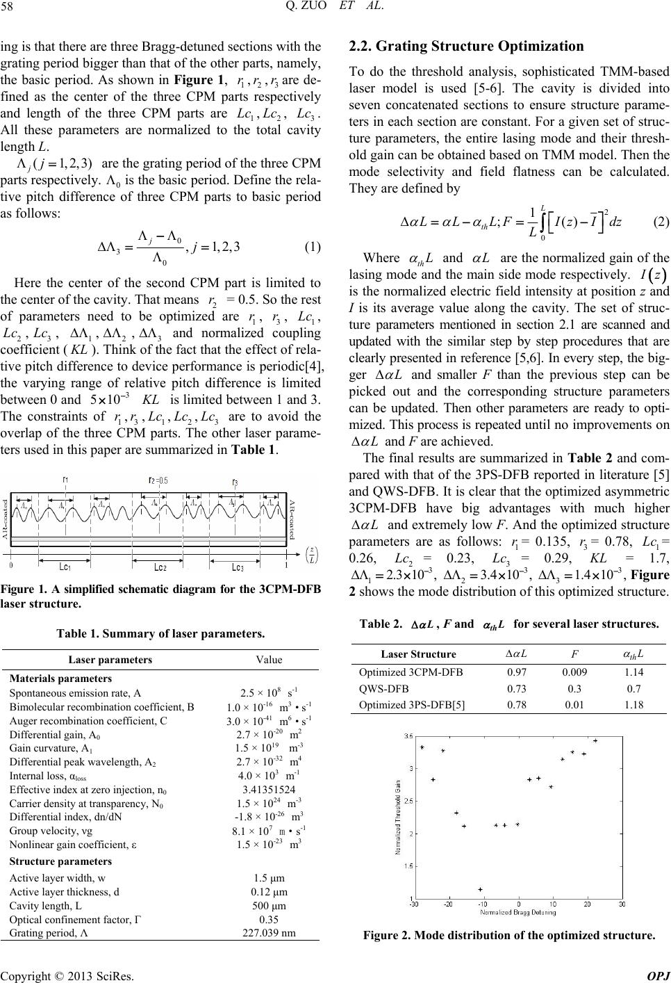 Q. ZUO ET AL. 58 ing is that there are three Bragg-detuned sections with the grating period bigger than that of the other parts, namely, the basic period. As shown in Figure 1, 1 r,2 r,3 rar de- fined as the center of the three CPM parts respectively and length of the three CPM parts are 1,2, 3. All these parameters are normalized to the total cavity length L. e ) Lc LcLc (1,2,3 jj are the grating period of the three CPM parts respectively. 0 is the basic period. Define the rela- tive pitch difference of three CPM parts to basic period as follows: 0 3 0 ,1,2, jj 3 = (1) Here the center of the second CPM part is limited to the center of the cavity. That means 2 r 0.5. So the rest of parameters need to be optimized are 1, 3, 1, 2,3, ,2,3 and normalized coupling coefficient (). Think of the fact that the effect of rela- tive pitch difference to device performance is periodic[4], the varying range of relative pitch difference is limited between 0 and is limited between 1 and 3. The constraints of 1,3,1,2,3 are to avoid the overlap of the three CPM parts. The other laser parame- ters used in this paper are summarized in Table 1. r rLc Lc Lc 1 KL 3 510 r r KL Lc Lc Lc Figure 1. A simplified schematic diagram for the 3CPM-DFB laser structure. Table 1. Summary of laser parameters. Laser parameters Value Materials parameters Spontaneous emission rate, A 2.5 × 10⁸ s-1 Bimolecular recombination coefficient, B 1.0 × 10⁻¹⁶ m3·s-1 Auger recombination coefficient, C 3.0 × 10-41 m6·s-1 Differential gain, A0 2.7 × 10⁻²⁰ m2 Gain curvature, A1 1.5 × 10¹⁹ m-3 Differential peak wavelength, A2 2.7 × 10⁻³² m4 Internal loss, αloss 4.0 × 10³ m-1 Effective index at zero injection, n0 3.41351524 Carrier density at transparency, N0 1.5 × 1024 m-3 Differential index, dn/dN -1.8 × 10⁻²⁶ m3 Group velocity, νg 8.1 × 10⁷ m·s-1 Nonlinear gain coefficient, ε 1.5 × 10⁻²³ m3 Structure parameters Active layer width, w 1.5 μm Active layer thickness, d 0.12 μm Cavity length, L 500 μm Optical confinement factor, Г 0.35 Grating period, Λ 227.039 nm 2.2. Grating Structure Optimization To do the threshold analysis, sophisticated TMM-based laser model is used [5-6]. The cavity is divided into seven concatenated sections to ensure structure parame- ters in each section are constant. For a given set of struc- ture parameters, the entire lasing mode and their thresh- old gain can be obtained based on TMM model. Then the mode selectivity and field flatness can be calculated. They are defined by 2 0 1 ;() L th LL LFIzId L z (2) Where th L and L are the normalized gain of the lasing mode and the main side mode respectively. I z is the normalized electric field intensity at position z and I is its average value along the cavity. The set of struc- ture parameters mentioned in section 2.1 are scanned and updated with the similar step by step procedures that are clearly presented in reference [5,6]. In every step, the big- ger L and smaller F than the previous step can be picked out and the corresponding structure parameters can be updated. Then other parameters are ready to opti- mized. This process is repeated until no improvements on L and F are achieved. The final results are summarized in Table 2 and com- pared with that of the 3PS-DFB reported in literature [5] and QWS-DFB. It is clear that the optimized asymmetric 3CPM-DFB have big advantages with much higher L and extremely low F. And the optimized structure parameters are as follows: = 0.135, 3= 0.78, 1= 0.26, = 0.23, = 0.29, = 1.7, 1 r 3 rLc 2 Lc 2.3 1 Lc KL 3 0 , 1 2 3 10 3. , 4 3 3, 1.4 10 Figure 2 shows the mode distribution of this optimized structure. Table 2. L, F and for several laser structures. thL Laser Structure L F th L Optimized 3CPM-DFB 0.97 0.009 1.14 QWS-DFB 0.73 0.3 0.7 Optimized 3PS-DFB[5] 0.78 0.01 1.18 Figure 2. Mode distribution of the optimized structure. Copyright © 2013 SciRes. OPJ 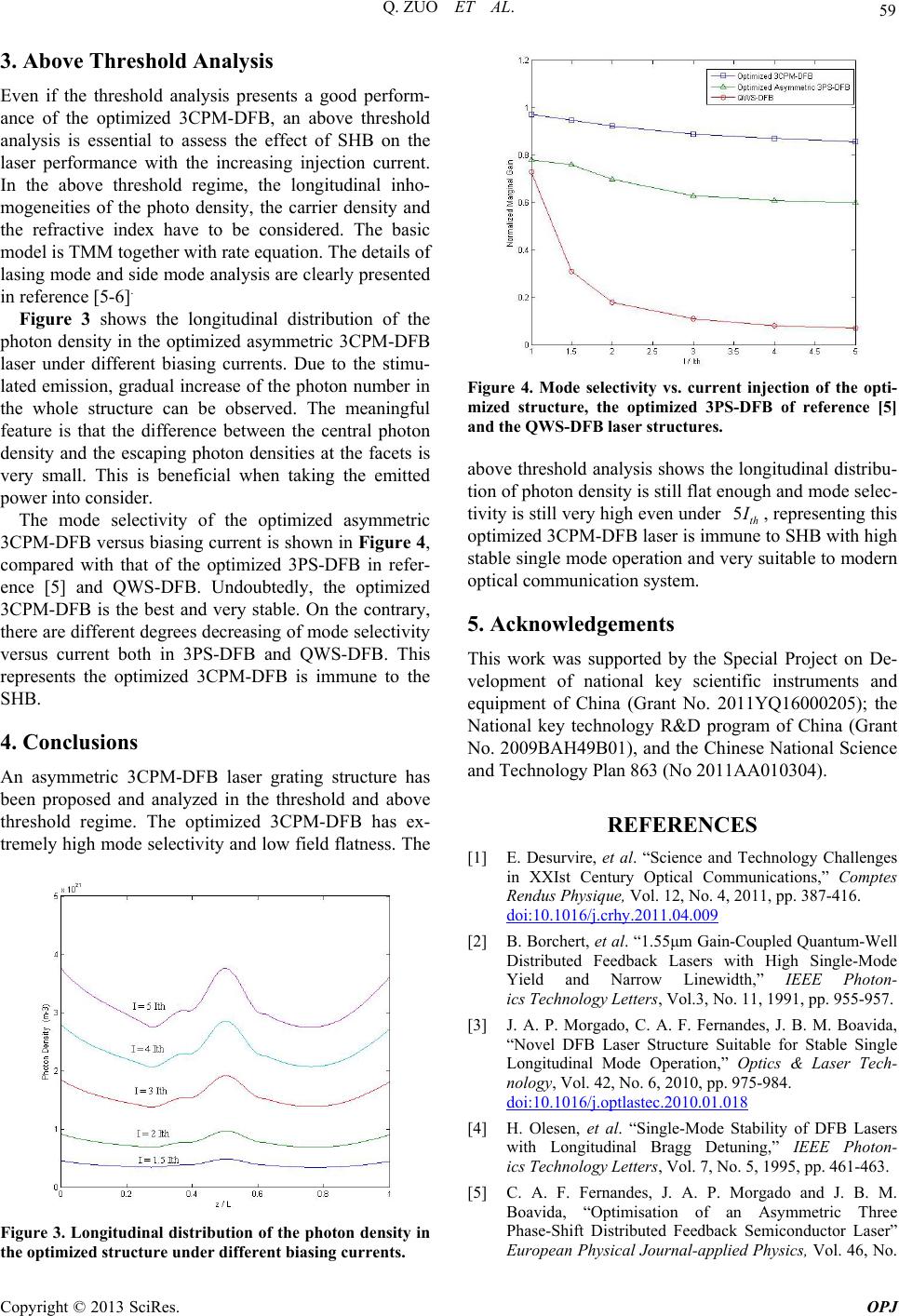 Q. ZUO ET AL. 59 3. Above Threshold Analysis Even if the threshold analysis presents a good perform- ance of the optimized 3CPM-DFB, an above threshold analysis is essential to assess the effect of SHB on the laser performance with the increasing injection current. In the above threshold regime, the longitudinal inho- mogeneities of the photo density, the carrier density and the refractive index have to be considered. The basic model is TMM together with rate equation. The details of lasing mode and side mode analysis are clearly presented in reference [5-6]. Figure 3 shows the longitudinal distribution of the photon density in the optimized asymmetric 3CPM-DFB laser under different biasing currents. Due to the stimu- lated emission, gradual increase of the photon number in the whole structure can be observed. The meaningful feature is that the difference between the central photon density and the escaping photon densities at the facets is very small. This is beneficial when taking the emitted power into consider. The mode selectivity of the optimized asymmetric 3CPM-DFB versus biasing current is shown in Figure 4, compared with that of the optimized 3PS-DFB in refer- ence [5] and QWS-DFB. Undoubtedly, the optimized 3CPM-DFB is the best and very stable. On the contrary, there are different degrees decreasing of mode selectivity versus current both in 3PS-DFB and QWS-DFB. This represents the optimized 3CPM-DFB is immune to the SHB. 4. Conclusions An asymmetric 3CPM-DFB laser grating structure has been proposed and analyzed in the threshold and above threshold regime. The optimized 3CPM-DFB has ex- tremely high mode selectivity and low field flatness. The Figure 3. Longitudinal distribution of the photon de nsity in the optimized structure under different biasing currents. Figure 4. Mode selectivity vs. current injection of the opti- mized structure, the optimized 3PS-DFB of reference [5] and the QWS-DFB laser structures. above threshold analysis shows the longitudinal distribu- tion of photon density is still flat enough and mode selec- tivity is still very high even under 5th I , representing this optimized 3CPM-DFB laser is immune to SHB with high stable single mode operation and very suitable to modern optical communication system. 5. Acknowledgements This work was supported by the Special Project on De- velopment of national key scientific instruments and equipment of China (Grant No. 2011YQ16000205); the National key technology R&D program of China (Grant No. 2009BAH49B01), and the Chinese National Science and Technology Plan 863 (No 2011AA010304). REFERENCES [1] E. Desurvire, et al. “Science and Technology Challenges in XXIst Century Optical Communications,” Comptes Rendus Physique, Vol. 12, No. 4, 2011, pp. 387-416. doi:10.1016/j.crhy.2011.04.009 [2] B. Borchert, et al. “1.55μm Gain-Coupled Quantum-Well Distributed Feedback Lasers with High Single-Mode Yield and Narrow Linewidth,” IEEE Photon- ics Technology Letters, Vol.3, No. 11, 1991, pp. 955-957. [3] J. A. P. Morgado, C. A. F. Fernandes, J. B. M. Boavida, “Novel DFB Laser Structure Suitable for Stable Single Longitudinal Mode Operation,” Optics & Laser Tech- nology, Vol. 42, No. 6, 2010, pp. 975-984. doi:10.1016/j.optlastec.2010.01.018 [4] H. Olesen, et al. “Single-Mode Stability of DFB Lasers with Longitudinal Bragg Detuning,” IEEE Photon- ics Technology Letters, Vol. 7, No. 5, 1995, pp. 461-463. [5] C. A. F. Fernandes, J. A. P. Morgado and J. B. M. Boavida, “Optimisation of an Asymmetric Three Phase-Shift Distributed Feedback Semiconductor Laser” European Physical Journal-applied Physics, Vol. 46, No. Copyright © 2013 SciRes. OPJ  Q. ZUO ET AL. Copyright © 2013 SciRes. OPJ 60 3, 2009, pp. 30701(1-9). doi:10.1051/epjap/2009068 [6] J. B. M. Boavida, J. A. P. Morgado and C. A. F. Fernan- des, “Optimisation of a Corrugation-Pitch-Modulated DFB Laser Structure with Inhomogeneous Coupling Co- efficient for Stable Single Longitudinal Mode Operation” European Physical Journal-applied Physics, Vol. 48, No. 3, 2009, pp. 30701 (1-10). doi:10.1051/epjap/2009186 [7] L. Wang, et al., “DFB LDs at DWDM Wavelengths Fab- ricated by a Novel Nanoimprint Process for Mass Produc- tion and Tolerance Simulation,” Microelectronic Engi- neering, Vol. 93, No. 1, 2012, pp. 43-49, doi:10.1016/j.mee.2011.08.001 [8] M. Yanagisawa, Y. Tsuji, H. Yoshinaga, N. Kono and K. Hiratsuka, “Evaluation of Nanoimprint Lithography as a Fabrication Process of Phase-Shifted Diffraction Gratings of Distributed Feedback Laser Diodes,” Journal of Vacuum Science & Technology, Vol. 27, No. 6, 2009, pp. 2776-2780. doi:10.1116/1.3244631 |