

Paper Menu >>
Journal Menu >>
 Open Journal of Metal, 2013, 3, 26-33 http://dx.doi.org/10.4236/ojmetal.2013.32A1004 Published Online July 2013 (http://www.scirp.org/journal/ojmetal) Equal Channel Angular Pressing of Al-SiC Composites Fabricated by Stir Casting Farouk Shehata1*, Nahed ElMahallawy2, Mohamed Arab1, Mohamed Agwa1 1Department of Mechanical Design and Production Engineering, Faculty of Engineering, Zagazig University, Zagazig, Egypt 2Faculty of Engineering, Ainshams University, Cairo, Egypt Email: *[email protected] Received May 9, 2013; revised June 19, 2013; accepted June 29, 2013 Copyright © 2013 Farouk Shehata et al. This is an open access article distributed under the Creative Commons Attribution License, which permits unrestricted use, distribution, and reproduction in any medium, provided the original work is properly cited. ABSTRACT Stir casting method was used to produce conventional metal matrix composites (MMC) with fairly homogenous disper- sion of reinforcement material. Commercial pure aluminum and silicon carbide particles (50 µm) were selected as ma- trix and reinforcement materials respectively. The matrix was first completely melt and kept constant at 750˚C. Then SiC powder preheated to 800˚C was added during stirring action. No wetting agents were used. The melt mixture was poured into a metallic mold. The composite contents were adjusted to contain 5% and 10% SiC. The as-cast composites were processed by Equal Channel Angular Pressing (ECAP) route A. The microstructure and mechanical properties were studied. Results indicated that as cast AlSiC composites can be successfully fabricated via a cheap conventional stir casting method, giving fairly dispersed SiC particle distribution and having low porosity levels < 3.6%. The me- chanical properties have improved compared to as cast composites. ECAP technique has greatly reduced SiC particles from 50 to 3 µm. After the first ECAP pass, yield strength has almost twice its value in the as cast composites. The maximum yield of 245 MPa obtained after 8 passes is almost four times the corresponding values of the as cast MMC composites. Hardness has also increased to 1.5 times its value in the as cast composites after one ECAP pass. The maximum hardness of 71 HRB obtained after 8 passes, which is almost 3.5 times the corresponding values of the as cast MMC composites. Keywords: Metal Matrix Composites; (Al-SiC) Composite; Porosity; Stir Casting 1. Introduction Metal matrix composites (MMC) have received much attention because of their improved mechanical proper- ties and relatively low cost, those have made them attrac- tive for numerous applications in various fields including aerospace, automotive and sports industries [1,2]. More specifically, particulate metal matrix composites (PMMCs) are attractive not only for their high mechanical proper- ties, but also because of their isotropic properties com- pared to the continuously reinforced MMCs [3,4]. Alu- minum silicon carbide (Al-SiC) composites have recently drawn the attention of many research scientists and tech- nologists. Several aspects are to be considered with re- gard to the metallic matrix, namely, composition, re- sponse to heat treatments, mechanical and corrosion be- havior. Since aluminum offers flexibility in terms of these aspects, accordingly, aluminum alloys have been used in several studies for research and technological applications. However, few numbers of researches, if any, have been published using pure aluminum as a matrix, they mostly use aluminium alloys. Pure aluminum tends to solidify progressively from the die surface toward the thermal center of the casting, pushing SiC particles towards the centre of casting. At the end of solidification, any shrinkage is confined along the thermal centerline of the casting. The progressive so- lidification of pure metal is therefore, difficult in avoid- ing SiC from sinking in the bottom of the casting. Aluminum alloys usually have broad freezing range. They are in a semisolid state throughout most of the so- lidification process. The semisolid state and wide mushy zone would be useful in avoiding SiC sink in bottom of casting. This usually made aluminum alloys preferred compared to pure metal in avoiding SiC aggregations. However, pure aluminium serves as a very ductile matrix and generally has higher corrosion resistance compared *Corresponding author. C opyright © 2013 SciRes. OJMetal 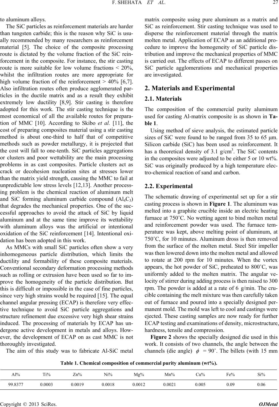 F. SHEHATA ET AL. 27 to aluminum alloys. The SiC particles as reinforcement materials are harder than tungsten carbide; this is the reason why SiC is usu- ally recommended by many researchers as reinforcement material [5]. The choice of the composite processing route is dictated by the volume fraction of the SiC rein- forcement in the composite. For instance, the stir casting route is more suitable for low volume fractions < 20%, whilst the infiltration routes are more appropriate for high volume fraction of the reinforcement > 40% [6,7]. Also infiltration routes often produce agglomerated par- ticles in the ductile matrix and as a result they exhibit extremely low ductility [8,9]. Stir casting is therefore adopted for this work. The stir casting technique is the most economical of all the available routes for prepara- tion of MMC [10]. According to Skibo et al. [11], the cost of preparing composites material using a stir casting method is about one-third to half that of competitive methods such as powder metallurgy, it is projected that the cost will fall to one-tenth. SiC particles aggregations or clusters and poor wettability are the main processing problems in as cast composites. Particle clusters act as crack or decohesion nucleation sites at stresses lower than the matrix yield strength, causing the MMC to fail at unpredictable low stress levels [12,13]. Another process- ing problem is the chemical reaction of aluminum melt and SiC forming aluminum carbide compound (Al4C3) that degrades the mechanical properties. One of the suc- cessful approaches to avoid the attack of SiC by liquid aluminum and at the same time improve its wettability with aluminum alloys was the artificial or intentional oxidation of the SiC reinforcement [14]. Intentional oxi- dation has been adopted in this work. As MMCs with small SiC particles often show a very inhomogeneous particle distribution, which limits the ductility and formability of these composite materials. Conventional secondary deformation processing methods such as rolling or extrusion have been used so far to im- prove the homogeneity of the particle distribution. But this is difficult or impossible in the case of fine particles, since very high strains would be required [15]. The equal channel angular pressing (ECAP) is therefore very effec- tive technique to avoid SiC particle aggregations and structure refinement due excessive very high shear strains induced. The processing of materials by ECAP has un- dergone active development in metals and alloys. How- ever, the development of ECAP on as cast MMC is not thoroughly investigated. The aim of this study was to fabricate Al-SiC metal matrix composite using pure aluminum as a matrix and SiC as reinforcement. Stir casting technique was used to disperse the reinforcement material through the matrix molten metal. Application of ECAP as an additional pro- cedure to improve the homogeneity of SiC particle dis- tribution and improve the mechanical properties of MMC is carried out. The effects of ECAP to different passes on SiC particle agglomerations and mechanical properties are investigated. 2. Materials and Experimental 2.1. Materials The composition of the commercial purity aluminum used for casting Al-matrix composite is as shown in Ta- ble 1. Using method of sieve analysis, the estimated particle sizes of SiC were found to be ranged from 35 to 65 μm. Silicon carbide (SiC) has been used as reinforcement. It has a theoretical density of 3.1 g/cm3. The SiC contents in the composites were adjusted to be either 5 or 10 wt%. SiC was originally produced by a high temperature elec- tro-chemical reaction of sand and carbon. 2.2. Experimental The schematic drawing of experimental set up for a stir casting process is shown in Figure 1. The aluminum was melted into a graphite crucible inside an electric heating furnace at 750˚C. No wetting agent to bind molten metal and reinforcement powder was used. The furnace tem- perature was kept, above melting point of aluminum, at 750˚C, for 10 minutes. Aluminum dross is then removed from the surface of the molten metal. Steel Stir impeller was then lowered down into the molten metal and allowed to rotate at 200 rpm for 10 minutes. When the vortex appears, the hot powder of SiC, preheated to 800˚C, was uniformly added to the molten matrix. The angular ve- locity of stirrer during adding process is then raised to 300 rpm. The powder is added at a rate of 6 g/min. The cru- cible containing the melt mixture was then carefully taken out of furnace and poured into a specially designed per- manent mold. The mold was left to cool and castings were ejected. These casting samples are now ready for further ECAP testing and examinations of density, microstructure, hardness, tensile and compression. Figure 2 shows the specially designed die used in this work. It consists of two channels, the angle between the channels (die angle) = 90˚. The billets (with 15 mm Table 1. Chemical composition of commercial purity aluminum (wt%). Al% Ti% Zn% Ni% Mg% Mn% Cu% Fe% Si% 99.8377 0.0003 0.0019 0.0018 0.0012 0.0021 0.005 0.09 0.06 Copyright © 2013 SciRes. OJMetal 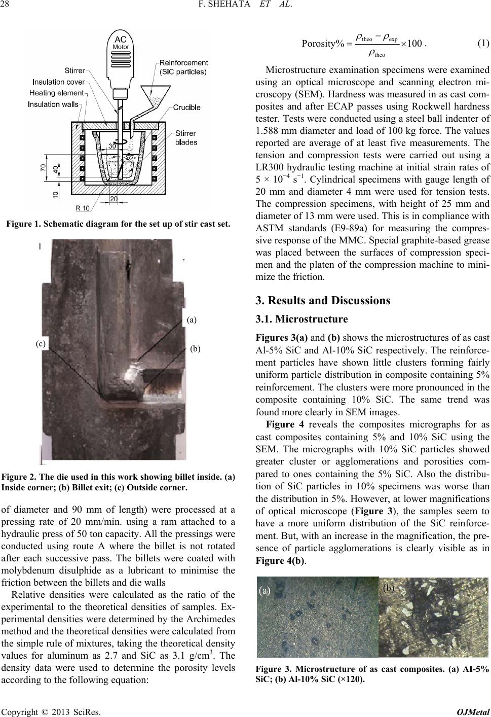 F. SHEHATA ET AL. 28 Figure 1. Schematic diagram for the set up of stir cast set. (a) (b) (c) Figure 2. The die used in this work showing billet inside. (a) Inside corner; (b) Billet exit; (c) Outside corner. of diameter and 90 mm of length) were processed at a pressing rate of 20 mm/min. using a ram attached to a hydraulic press of 50 ton capacity. All the pressings were conducted using route A where the billet is not rotated after each successive pass. The billets were coated with molybdenum disulphide as a lubricant to minimise the friction between the billets and die walls Relative densities were calculated as the ratio of the experimental to the theoretical densities of samples. Ex- perimental densities were determined by the Archimedes method and the theoretical densities were calculated from the simple rule of mixtures, taking the theoretical density values for aluminum as 2.7 and SiC as 3.1 g/cm3. The density data were used to determine the porosity levels according to the following equation: theo exp theo Porosity% 100 . (1) Microstructure examination specimens were examined using an optical microscope and scanning electron mi- croscopy (SEM). Hardness was measured in as cast com- posites and after ECAP passes using Rockwell hardness tester. Tests were conducted using a steel ball indenter of 1.588 mm diameter and load of 100 kg force. The values reported are average of at least five measurements. The tension and compression tests were carried out using a LR300 hydraulic testing machine at initial strain rates of 5 × 10⁻⁴ s−1. Cylindrical specimens with gauge length of 20 mm and diameter 4 mm were used for tension tests. The compression specimens, with height of 25 mm and diameter of 13 mm were used. This is in compliance with ASTM standards (E9-89a) for measuring the compres- sive response of the MMC. Special graphite-based grease was placed between the surfaces of compression speci- men and the platen of the compression machine to mini- mize the friction. 3. Results and Discussions 3.1. Microstructure Figures 3(a) and (b) shows the microstructures of as cast Al-5% SiC and Al-10% SiC respectively. The reinforce- ment particles have shown little clusters forming fairly uniform particle distribution in composite containing 5% reinforcement. The clusters were more pronounced in the composite containing 10% SiC. The same trend was found more clearly in SEM images. Figure 4 reveals the composites micrographs for as cast composites containing 5% and 10% SiC using the SEM. The micrographs with 10% SiC particles showed greater cluster or agglomerations and porosities com- pared to ones containing the 5% SiC. Also the distribu- tion of SiC particles in 10% specimens was worse than the distribution in 5%. However, at lower magnifications of optical microscope (Figure 3), the samples seem to have a more uniform distribution of the SiC reinforce- ment. But, with an increase in the magnification, the pre- sence of particle agglomerations is clearly visible as in Figure 4(b). Figure 3. Microstructure of as cast composites. (a) AI-5% SiC; (b) Al-10% SiC (×120). Copyright © 2013 SciRes. OJMetal 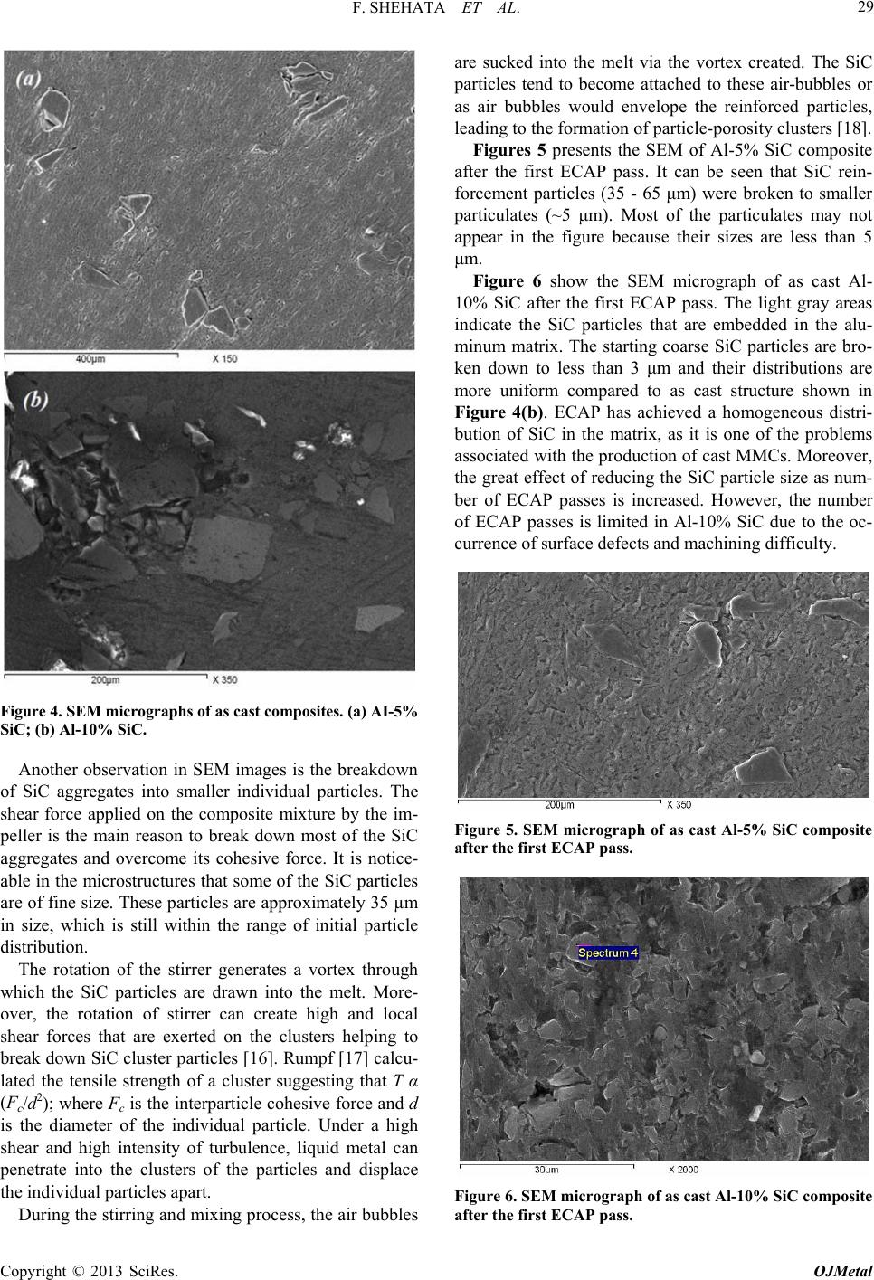 F. SHEHATA ET AL. 29 Figure 4. SEM micrographs of as cast composites. (a) AI-5% SiC; (b) Al-10% SiC. Another observation in SEM images is the breakdown of SiC aggregates into smaller individual particles. The shear force applied on the composite mixture by the im- peller is the main reason to break down most of the SiC aggregates and overcome its cohesive force. It is notice- able in the microstructures that some of the SiC particles are of fine size. These particles are approximately 35 µm in size, which is still within the range of initial particle distribution. The rotation of the stirrer generates a vortex through which the SiC particles are drawn into the melt. More- over, the rotation of stirrer can create high and local shear forces that are exerted on the clusters helping to break down SiC cluster particles [16]. Rumpf [17] calcu- lated the tensile strength of a cluster suggesting that T α (Fc/d2); where Fc is the interparticle cohesive force and d is the diameter of the individual particle. Under a high shear and high intensity of turbulence, liquid metal can penetrate into the clusters of the particles and displace the individual particles apart. During the stirring and mixing process, the air bubbles are sucked into the melt via the vortex created. The SiC particles tend to become attached to these air-bubbles or as air bubbles would envelope the reinforced particles, leading to the formation of particle-porosity clusters [18]. Figures 5 presents the SEM of Al-5% SiC composite after the first ECAP pass. It can be seen that SiC rein- forcement particles (35 - 65 μm) were broken to smaller particulates (~5 μm). Most of the particulates may not appear in the figure because their sizes are less than 5 μm. Figure 6 show the SEM micrograph of as cast Al- 10% SiC after the first ECAP pass. The light gray areas indicate the SiC particles that are embedded in the alu- minum matrix. The starting coarse SiC particles are bro- ken down to less than 3 μm and their distributions are more uniform compared to as cast structure shown in Figure 4(b). ECAP has achieved a homogeneous distri- bution of SiC in the matrix, as it is one of the problems associated with the production of cast MMCs. Moreover, the great effect of reducing the SiC particle size as num- ber of ECAP passes is increased. However, the number of ECAP passes is limited in Al-10% SiC due to the oc- currence of surface defects and machining difficulty. Figure 5. SEM micrograph of as cast Al-5% SiC composite after the first ECAP pass. Figure 6. SEM micrograph of as cast Al-10% SiC composite after the first ECAP pass. Copyright © 2013 SciRes. OJMetal  F. SHEHATA ET AL. 30 3.2. Porosity Contents Table 2 presents the comparison of the theoretical and the experimental densities of Al-5% SiC and Al-10% SiC compared to monolithic aluminum. It is shown that the experimental density is always less than theoretical one. The densities of the composites are higher than that of the monolithic aluminum. The experimental densities of composites have in- creased as reinforcement is increased up to 5% SiC; upon further increase to 10% SiC the composite experimental showed little decrease. This is probably due to air and gases that usually attached to the reinforcement particles. The amount of gas porosity in casting depends more on the volume fraction of reinforcement. However, there are several strategies that have been used in literature to minimize porosity, such as vacuum casting, inert gas bubbling through the melt, die casting, extrusion and rol- ling. In this work we adopt severe plastic deformation using equi channel axial pressing (ECAP) technique to con- solidate the composite and minimize the porosity. Figure 7 shows the effect of increase numbers of ECAP passes on porosity percentage. As number of ECAP passes are increased, the porosity percentages are greatly decreased. It reached 1.1% after 8 passes in alu- minum containing 5% SiC. The gases that dissolved during stirring of molten metal would lead to formation of porosities on solidifica- tion. The theoretical and experimental densities were used to estimate porosity percentage using Equation (1). Table 2. Comparison of the theoretical and the experimen- tal densities. Theo density g/cc Exper. density g/cc Porosity% Al 0% SiC 2.700 2.640 2.222 Al 5% SiC 2.720 2.658 2.279 Al 10% SiC 2.740 2.648 3.358 Figure 7. The effect of increasing number of ECAP passes on porosity percentage. The maximum value of porosity is 3.36%, shown in Fig- ure 5, represents the as cast composite without any ECAP process. Many researchers [17,18] have used al- ternative stirring processes and reported that porosity levels were within range of 2% to 4%, which were re- ferred to as an acceptable level of porosity in cast com- posites. This indicates that in spite of high level of poros- ity in this work (up to 3.36%) it is still considered as an acceptable and suitable for preparing the AlSiC compos- ites. Porosity level and distribution in MMC usually play an important role in controlling the mechanical properties. It is thus necessary that porosity levels be kept to a mini- mum if high performance in service applications is de- sired. Applying ECAP technique on as cast composites gave a great reduction in porosity level. Porosity values of 1.1 and 1.31 were obtained for Al-5% SiC and Al-10% SiC respectively after 8 ECAP passes. It is noted that the greatest porosity reduction (>40%) was achieved after the first pass. Further ECAP passes may lead to extensive nucleation of voids which will limit the improvement in porosity percentage [19,20]. 3.3. Mechanical Properties Figure 8 shows the tensile engineering stress-strain curves for as cast composites Al-5% SiC and Al-10% SiC compared to pure aluminum matrix material. These curves are taken from the load-elongation curves ob- tained from the tensile testing machine. Figure 9 shows the compression engineering stress- strain curves for as cast composites; Al-5% SiC and Al- 10% SiC compared to pure aluminum matrix material. Again these curves are taken from the engineering load- reduction in height curves obtained from the compression testing machine. The results of compression test are simi- lar to tension test results. The curves showed that, in- creasing the content of SiC reinforcement particles in- creased the compressive strength of the composite. In compression tests, at 20% reduction in height, the compression strength showed a significant increase with increase of silicon carbide content in the matrix up to 5% SiC. Further increase in SiC to 10% also showed an in- crease in compression but with lower rate. The increase in compression strength is much higher than that the cor- responding increases in tension strength. Figure 10 shows a comparison of various mechanical properties of pure aluminum, Al-5% SiC and Al-10% SiC composites produced by stir casting before conduct- ing ECAP process. The yield and ultimate tensile strengths (UTS) in both composites increased with increasing the SiC wt% compared to unreinforced pure metal. The largest increase was found in Al-10% SiC MMC. The UTS of both composites showed an increase of 97% and 68% over the corresponding value of the as cast pure aluminum. Copyright © 2013 SciRes. OJMetal  F. SHEHATA ET AL. 31 Figure 8. Engineering stress-strain curves from tension tests of as cast composites. Figure 9. Engineering stress-strain curves from compres- sion tests of as cast composites. Figure 10. Comparison of various mechanical properties for as cast composites with different percentages of SiC. The compression strength (at-0.2 stain) showed much higher increase of 297% and 218% over the correspond- ing value of as cast pure aluminum. The improvement in strengths of MMC is resulting from the effective disper- sion of the SiC particles fabricated by stir casting method. This can be attributed to closure action of any micro cracks that might appear. It should be noticed that there were no fracture in compression specimens due to the high ductility of the pure aluminum matrix. The same trend was found in hardness values as show in histogram of Figure 8. The magnitude of the hardness increase is about 67%. The increase in strength and hardness of the composite is accompanied by a little reduction in uni- form elongations due to embrittlement action of ceramic (SiC) particles. Figure 11 shows the 0.2% proof stress of the composites in as cast (0 Pass) and after each ECAP pass in compression tests. For composites containing 5% and 10% SiC, the yield strengths are tremendously in- creased as numbers of ECAP passes are increased. After the first pass, yield strength has almost twice the value of the as cast composites. The maximum yield obtained after 8 passes for both composites showed almost four times the corresponding values of the as cast MMC com- posites. It is also noticed that composites containing 10% SiC showed little higher strengths (~10%) after all passes compared to ones contain 5% SiC. Figure 12 shows the effect increasing number of ECAP passes on average hardness values for composites containing 5% and 10% SiC particles. The hardness val- ues show the same trend as yield strength values. For composites containing 5% and 10% SiC, the hardness Figure 11. The 0.2% proof stress of the composites in as cast (0 Pass) and after each ECAP pass against number of ECAP passes. Figure 12. The hardness of the composites in as cast (0 Pass) and after each ECAP pass against number of ECAP passes. Copyright © 2013 SciRes. OJMetal  F. SHEHATA ET AL. 32 values are increased as numbers of ECAP passes are in- creased. After the first pass, the hardness has increased to 1.5 times the as cast composites. The maximum hardness obtained after 8 passes for both composites showed al- most 2.9 to 3.5 times higher than the corresponding val- ues of the as cast MMC composites. It was found that 0.2% proof stress and hardness of both the composites after ECAP are impressively higher than as cast pure aluminium used in this work. The flow stress of pure aluminium after eight ECAP passes is re- ported to be 132 MPa [21] compared to 233 MPa in this work which is considerably higher than the repotted value. This may indicate that the SiC is very effective in increasing strength or hardness when ECAP is applied. As shown Al-10% SiC shows higher strength than Al-5% SiC composite due to presence of higher amount of SiC particles. Dislocations are generated due to mismatch in thermal expansion coefficient between the matrix and the reinforcement. As a result, the matrix of composites con- tains higher dislocation. Higher the volume fraction of reinforcement higher will be the dislocation density. This leads to higher hardness and strength with increase in SiC content. 4. Conclusions 1) Commercial purity aluminum matrix with SiC rein- forcement can be successfully fabricated using conven- tional low cost method of stir casting. 2) The distribution of silicon carbide particles has shown an aggregate structure in as cast composites. The stir cast leads to breaking down most of the SiC aggregates. 3) Composite reinforced with 10% SiC showed greater agglomerations and porosities compared to 5% SiC in as cast condition. 4) ECAP techniques resulted in structural refinement and SiC particles have greatly reduced from 50 µm to 5 µm in Al-5% SiC and 3 µm in Al-10% SiC after the first ECAP pass. 5) The as cast AlSiC composites indicated porosities up to 3.6%. After eight ECAP passes, porosity was reduced 1.1 and 1.31% for Al-5% SiC and Al-10% SiC respectively. 6) After the first ECAP pass, yield strength has almost twice its value in the as cast composites. The maximum yield of 245 MPa obtained after 8 passes is almost four times the corresponding values of the as cast MMC com- posites. 7) After the first ECAP pass, hardness has almost 1.5 times its value in the as cast composites. The maximum hardness of 71 HRB obtained after 8 passes is almost 3.5 times the corresponding values of the as cast MMC composites. REFERENCES [1] T. W. Cline and P. J. Withers, “An Introduction to Metal Matrix Composites,” Cambridge University Press, Cam- bridge, 1995. [2] D. B. Miracle, “Metal Matrix Composites—From Science to Technological Significance,” Composites Science and Technology, Vol. 65, No. 15, 2005, pp. 2526-2540. doi:10.1016/j.compscitech.2005.05.027 [3] D. J. Lloyd, “Particle Reinforced Aluminum and Magne- sium Matrix Composites,” International Materials Re- views, Vol. 39, No. 1, 1994, pp. 1-23. doi:10.1179/095066094790150982 [4] S. Ray, “Synthesis of Cast Metal Matrix Particulate Com- posites,” Journal of Materials Science, Vol. 28, No. 20, 1993, pp. 5397-5413. doi:10.1007/BF00367809 [5] L. Cronjager and M. Dietmar, “Drilling of Fibre and Par- ticle Reinforced Aluminum,” Composite Material Tech- nology, Vol. 37, 1991, pp. 185-189. [6] M.-R. Chen, et al., “Microstructure and Properties of Al0.5CoCrCuFeNiTix (x = 0 - 2.0) High-Entropy Alloys,” 2006. [7] P. K. Rohatgi, “Low-Cost, Fly-Ash-Containing Alumi- num-Matrix Composites,” JOM, Vol. 46, No. 11, 1994, pp. 55-59. doi:10.1007/BF03222635 [8] M. I. Pech-Canul, “Aluminum Alloys for Al/SiC Com- posites,” Recent Trends in Processing and Degradation of Aluminum Alloys, 2011, pp. 299-314. [9] Y. Cui, “High Volume Fraction SiCp/Al Composites Pre- pared by Pressureless Melt Infiltration: Processing, Prop- erties and Applications,” Key Engineering Materials, Vol. 249, 2003, pp. 45-48. doi:10.4028/www.scientific.net/KEM.249.45 [10] M. K. Surappa, “Microstructure Evolution during Solidi- fication of DRMMC,” Journal of Materials Processing Technology, Vol. 63, 1997, pp. 325-333. doi:10.1016/S0924-0136(96)02643-X [11] D. M. Skibo, D. M. Schuster and L. Jolla, “Process for Preparation of Composite Materials Containing Non-Me- tallic Particles in a Metallic Matrix, and Composite Mate- rials,” US Patent No. 4786467, 1988. [12] D. J. Lloyd, “Aspects of Fracture in Particulate Rein- forced Metal Matrix Composites,” Acta metallurgica et materialia, Vol. 39, No. 1, 1991, pp. 59-71. doi:10.1016/0956-7151(91)90328-X [13] Y. M. Youssef, R. J. Dashwood and P. D. Lee, “Effect of Clustering on Particle Pushing and Solidification Behav- ior in TiB2 Reinforced Aluminum PMMCs,” Composites Part A: Applied Science and Manufacturing, Vol. 36, No. 6, 2005, pp. 747-763. doi:10.1016/j.compositesa.2004.10.027 [14] T. Iseki, T. Kameda and T. Maruyama, “Interfacial Reac- tions between SiC and Aluminum during Joining,” Jour- nal of Materials Science, Vol. 19, No. 5, 1984, pp. 1692- 1698. doi:10.1007/BF00563067 [15] I. Sabirov, O. Kolednik, R. Z. Valiev and R. Pippan, “Equal Channel Angular Pressing of Metal Matrix Com- posites,” Acta Materialia, Vol. 53, 2005, pp. 4919-4930. doi:10.1016/j.actamat.2005.07.010 [16] S. Tzamtzis, et al., “Processing of Advanced Al/SiC Par- Copyright © 2013 SciRes. OJMetal  F. SHEHATA ET AL. Copyright © 2013 SciRes. OJMetal 33 ticulate Metal Matrix Composites under Intensive Shear- ing—A Novel Rheo-Process,” Composites Part A: Ap- plied Science and Manufacturing, Vol. 40, No. 2, 2009, pp. 144-151. doi:10.1016/j.compositesa.2008.10.017 [17] H. Rumpf, “The Strength of Granules and Agglomerates,” Agglomeration, Interscience, New York, 1962, pp. 379- 413. [18] P. N. Bindumadhavan, T. K. Chia, M. Chandrasekaran, H. K. Wah, L. N. Lam and O. Prabhakar, “Effect of Particle Porosity Clusters on Tribological Behavior of Cast Alu- minium Alloy A356-SiCp Metal Matrix Composites,” Materials Science and Engineering: A, Vol. 315, No. 1-2, 2001, pp. 217-226. doi:10.1016/S0921-5093(00)01989-4 [19] M. Kok, “Production and Mechanical Properties of Al2O3 Particle-Reinforced 2024 Aluminum Alloy Composites,” Journal of Materials Processing Technology, Vol. 161, No. 3, 2005, pp. 381-387. doi:10.1016/j.jmatprotec.2004.07.068 [20] J. W. Martin, R. D. Doherty and B. Cantor, “Stability of Microstructure in Metallic Systems,” Cambridge Univer- sity Press, Cambridge, 1997. doi:10.1017/CBO9780511623134 [21] T. Inoue, Z. Horita, H. Somekawa and K. Ogawa, “Effect of Initial Grain Sizes on Hardness Variation and Strain Distribution of Pure Aluminum Severely Deformed by Compression Tests,” Acta Materialia, Vol. 56, No. 20, 2008, pp. 6291-6303. doi:10.1016/j.actamat.2008.08.042 |