

Paper Menu >>
Journal Menu >>
 Open Journal of Inorganic Non-Metallic Materials, 2013, 3, 37-42 http://dx.doi.org/10.4236/ojinm.2013.33007 Published Online July 2013 (http://www.scirp.org/journal/ojinm) Syntheses of Doped-LaCrO3 Nanopowders by Hydrothermal Method Minkyung Kang, Juyeon Yun, Chiwook Cho, Changyoon Kim, Weonpil Tai* Fine Chemical and Material Technical Institute, Ulsan Techno Park, Ulsan, Republic of Korea Email: *[email protected] Received March 28, 2013; revised April 25, 2013; accepted May 9, 2013 Copyright © 2013 Minkyung Kang et al. This is an open access article distributed under the Creative Commons Attribution License, which permits unrestricted use, distribution, and reproduction in any medium, provided the original work is properly cited. ABSTRACT The effects of additives and precipitants on the syntheses of doped LaCrO3 (lanthanum chromites) were studied by hydrothermal reaction at temperature ranges of 100˚C to 230˚C. LaCrO3 nanopowders were synthesized by hydrother- mal methods using several types of precipitants such as NaOH, KOH, NH4OH, and NH2CONH2. The influence of Sr, Ca and Co doping on the lanthanum chromites prepared by hydrothermal method were investigated. The synthesized nanopowders were characterized by means of XRD, SEM and densitometer. The electrical conductivity of the doped LaCrO3 was studied at 750˚C in air by a DC four point probe method. The particles size of undoped LaCrO3 nanopow- der was approximately 100 nm when using KOH as a precipitant. The relative density of lanthanum chromite doped with calcium and cobalt is over 97%. The highest electrical conductivity of La0.62Ca0.38Co0.18Cr0.82O3 was 32.75 S/cm at 750˚C in air, which is 30 times higher than undoped LaCrO3. The density and electrical conductivity are increased by doping cobalt and calcium on the LaCrO3. Keywords: Doped LaCrO3; Hydrothermal Reactions; Interconnects for Solid Oxide Fuel Cell 1. Introduction The interconnect of a SOFC stack electrically and physi- cally is connected to the anode of one unit cell with the cathode of the adjacent unit cell in the stack. The inter- connect can be ceramic or metallic materials. The inter- connect materials used for SOFC stacks must be elec- tronically conductive, oxidation resistant, impermeable to the diffusion of gases, and chemically stable with fuel cell materials [1]. There are suitable materials, such as ceramics and metals for interconnect in solid oxide fuel cell (SOFC). Each material has advantages, but neither is ideal. Metallic chromium-forming alloys are most com- monly used, but the formation of chromium-containing vapor species can lead to poisoning of the cathode after long operation. The resistance to this degradation can be improved through a combination of the two materials by ceramic coating on the metallic interconnect [2]. Ceramic interconnects based upon ceramic oxides with perovskite structure have been subject of intensive study over the past several decades. It was found that only a few such oxides systems can fulfill the rigorous require- ments for the interconnect materials in SOFC. Lantha- num chromites (LaCrO3) is the most common candidate material since it demonstrates reasonably high electronic conductivity in both fuel and oxidant atmospheres, mod- erate stability in the fuel cell environments as well as fairly good compatibility with other cell components in terms of phase, microstructure and thermal expansion. In order to improve the electrical conductivity as well as modify the thermal expansion coefficient (TEC), LaCrO3 is often doped on lanthanum site, chromium site or both sites of the perovskite for practical applications. Due to ionic radius similarity, strontium and calcium tend to replace La ions whereas magnesium, iron, nickel, copper and cobalt prefer to take over the site of Cr ions. As a matter of fact, in SOFC configuration, the doped LaCrO3 is still the most widely used as an interconnect [3]. Nanotechnology is the key for enhancing the perfor- mance of fuel cell. It is being used to lower the operating temperature of solid oxide fuel cells (SOFC). Also it can improve durability and increase oxygen-ion conductivity in the low temperature. The interconnect materials pre- pared using nanopowders in SOFC could be decreased the sintering temperature due to higher surface area. Also, it is advantageous for the formation of the dense film to have high temperature durability [4]. *Corresponding author. C opyright © 2013 SciRes. OJINM 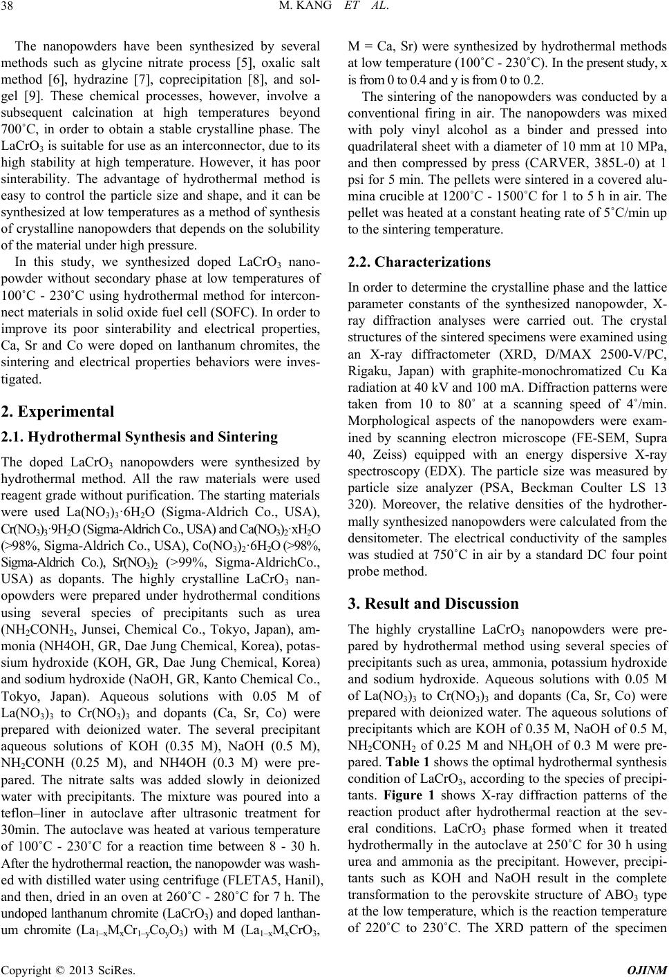 M. KANG ET AL. 38 The nanopowders have been synthesized by several methods such as glycine nitrate process [5], oxalic salt method [6], hydrazine [7], coprecipitation [8], and sol- gel [9]. These chemical processes, however, involve a subsequent calcination at high temperatures beyond 700˚C, in order to obtain a stable crystalline phase. The LaCrO3 is suitable for use as an interconnector, due to its high stability at high temperature. However, it has poor sinterability. The advantage of hydrothermal method is easy to control the particle size and shape, and it can be synthesized at low temperatures as a method of synthesis of crystalline nanopowders that depends on the solubility of the material under high pressure. In this study, we synthesized doped LaCrO3 nano- powder without secondary phase at low temperatures of 100˚C - 230˚C using hydrothermal method for intercon- nect materials in solid oxide fuel cell (SOFC). In order to improve its poor sinterability and electrical properties, Ca, Sr and Co were doped on lanthanum chromites, the sintering and electrical properties behaviors were inves- tigated. 2. Experimental 2.1. Hydrothermal Synthesis and Sintering The doped LaCrO3 nanopowders were synthesized by hydrothermal method. All the raw materials were used reagent grade without purification. The starting materials were used La(NO3)3·6H2O (Sigma-Aldrich Co., USA), Cr(NO3)3·9H2O (Sigma-Aldrich Co., USA) and Ca(NO3)2·xH2O (>98%, Sigma-Aldrich Co., USA), Co(NO3)2·6H2O (>98%, Sigma-Aldrich Co.), Sr(NO3)2 (>99%, Sigma-AldrichCo., USA) as dopants. The highly crystalline LaCrO3 nan- opowders were prepared under hydrothermal conditions using several species of precipitants such as urea (NH2CONH2, Junsei, Chemical Co., Tokyo, Japan), am- monia (NH4OH, GR, Dae Jung Chemical, Korea), potas- sium hydroxide (KOH, GR, Dae Jung Chemical, Korea) and sodium hydroxide (NaOH, GR, Kanto Chemical Co., Tokyo, Japan). Aqueous solutions with 0.05 M of La(NO3)3 to Cr(NO3)3 and dopants (Ca, Sr, Co) were prepared with deionized water. The several precipitant aqueous solutions of KOH (0.35 M), NaOH (0.5 M), NH2CONH (0.25 M), and NH4OH (0.3 M) were pre- pared. The nitrate salts was added slowly in deionized water with precipitants. The mixture was poured into a teflon–liner in autoclave after ultrasonic treatment for 30min. The autoclave was heated at various temperature of 100˚C - 230˚C for a reaction time between 8 - 30 h. After the hydrothermal reaction, the nanopowder was wash- ed with distilled water using centrifuge (FLETA5, Hanil), and then, dried in an oven at 260˚C - 280˚C for 7 h. The undoped lanthanum chromite (LaCrO3) and doped lanthan- um chromite (La1–xMxCr1–yCoyO3) with M (La1–xMxCrO3, M = Ca, Sr) were synthesized by hydrothermal methods at low temperature (100˚C - 230˚C). In the present study, x is from 0 to 0.4 and y is from 0 to 0.2. The sintering of the nanopowders was conducted by a conventional firing in air. The nanopowders was mixed with poly vinyl alcohol as a binder and pressed into quadrilateral sheet with a diameter of 10 mm at 10 MPa, and then compressed by press (CARVER, 385L-0) at 1 psi for 5 min. The pellets were sintered in a covered alu- mina crucible at 1200˚C - 1500˚C for 1 to 5 h in air. The pellet was heated at a constant heating rate of 5˚C/min up to the sintering temperature. 2.2. Characterizations In order to determine the crystalline phase and the lattice parameter constants of the synthesized nanopowder, X- ray diffraction analyses were carried out. The crystal structures of the sintered specimens were examined using an X-ray diffractometer (XRD, D/MAX 2500-V/PC, Rigaku, Japan) with graphite-monochromatized Cu Ka radiation at 40 kV and 100 mA. Diffraction patterns were taken from 10 to 80˚ at a scanning speed of 4˚/min. Morphological aspects of the nanopowders were exam- ined by scanning electron microscope (FE-SEM, Supra 40, Zeiss) equipped with an energy dispersive X-ray spectroscopy (EDX). The particle size was measured by particle size analyzer (PSA, Beckman Coulter LS 13 320). Moreover, the relative densities of the hydrother- mally synthesized nanopowders were calculated from the densitometer. The electrical conductivity of the samples was studied at 750˚C in air by a standard DC four point probe method. 3. Result and Discussion The highly crystalline LaCrO3 nanopowders were pre- pared by hydrothermal method using several species of precipitants such as urea, ammonia, potassium hydroxide and sodium hydroxide. Aqueous solutions with 0.05 M of La(NO3)3 to Cr(NO3)3 and dopants (Ca, Sr, Co) were prepared with deionized water. The aqueous solutions of precipitants which are KOH of 0.35 M, NaOH of 0.5 M, NH2CONH2 of 0.25 M and NH4OH of 0.3 M were pre- pared. Table 1 shows the optimal hydrothermal synthesis condition of LaCrO3, according to the species of precipi- tants. Figure 1 shows X-ray diffraction patterns of the reaction product after hydrothermal reaction at the sev- eral conditions. LaCrO3 phase formed when it treated hydrothermally in the autoclave at 250˚C for 30 h using urea and ammonia as the precipitant. However, precipi- tants such as KOH and NaOH result in the complete transformation to the perovskite structure of ABO3 type at the low temperature, which is the reaction temperature of 220˚C to 230˚C. The XRD pattern of the specimen Copyright © 2013 SciRes. OJINM 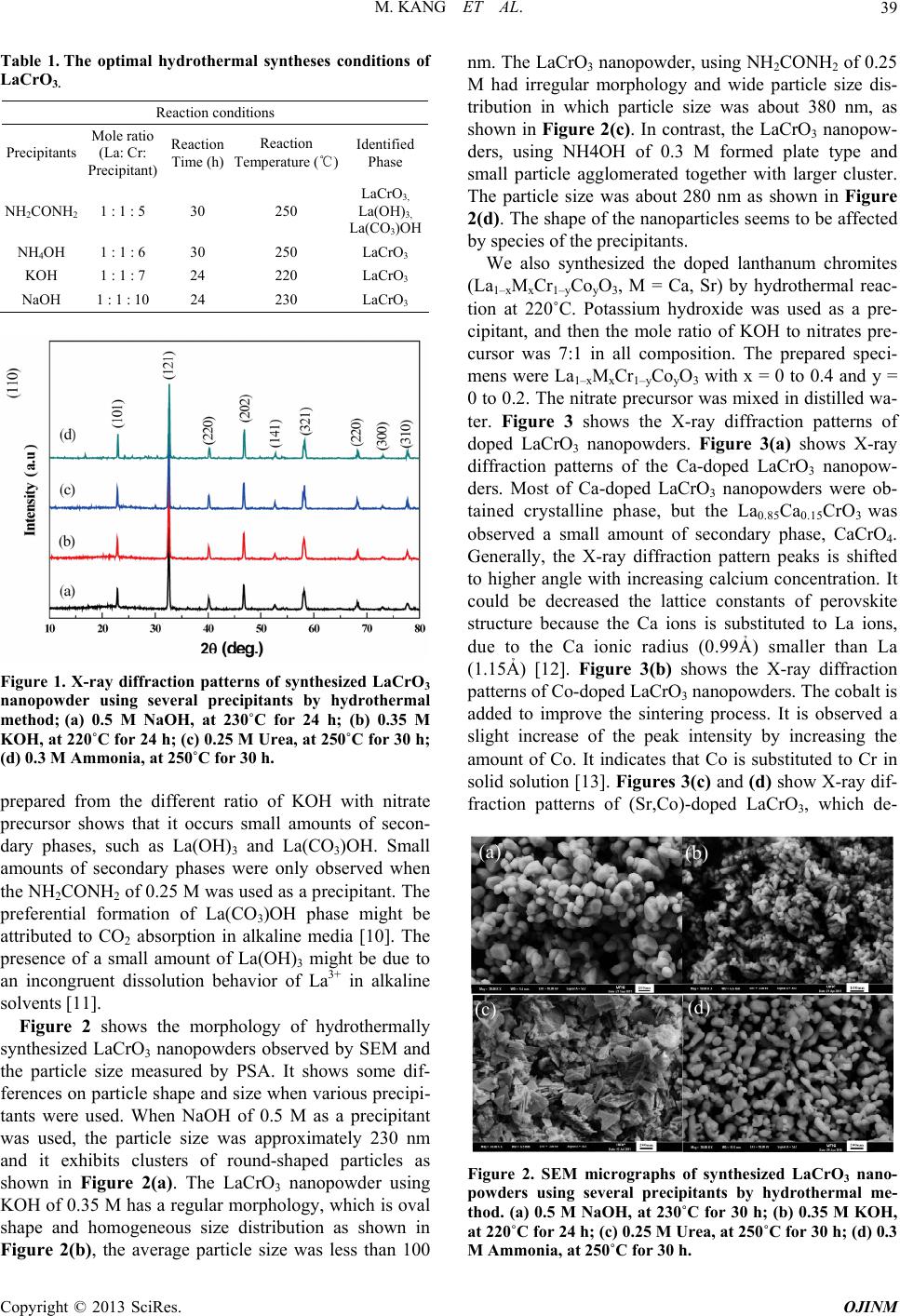 M. KANG ET AL. 39 Table 1 . The optimal hydrothermal syntheses conditions of LaCrO3. Reaction conditions Precipitants Mole ratio (La: Cr: Precipitant) Reaction Time (h) Reaction Temperature (℃) Identified Phase NH2CONH2 1 : 1 : 5 30 250 LaCrO3, La(OH)3, La(CO3)OH NH4OH 1 : 1 : 6 30 250 LaCrO3 KOH 1 : 1 : 7 24 220 LaCrO3 NaOH 1 : 1 : 10 24 230 LaCrO3 Figure 1. X-ray diffraction patterns of synthesized LaCrO3 nanopowder using several precipitants by hydrothermal method; (a) 0.5 M NaOH, at 230˚C for 24 h; (b) 0.35 M KOH, at 220˚C for 24 h; (c) 0.25 M Urea, at 250˚C for 30 h; (d) 0.3 M Ammonia, at 250˚C for 30 h. prepared from the different ratio of KOH with nitrate precursor shows that it occurs small amounts of secon- dary phases, such as La(OH)3 and La(CO3)OH. Small amounts of secondary phases were only observed when the NH2CONH2 of 0.25 M was used as a precipitant. The preferential formation of La(CO3)OH phase might be attributed to CO2 absorption in alkaline media [10]. The presence of a small amount of La(OH)3 might be due to an incongruent dissolution behavior of La3+ in alkaline solvents [11]. Figure 2 shows the morphology of hydrothermally synthesized LaCrO3 nanopowders observed by SEM and the particle size measured by PSA. It shows some dif- ferences on particle shape and size when various precipi- tants were used. When NaOH of 0.5 M as a precipitant was used, the particle size was approximately 230 nm and it exhibits clusters of round-shaped particles as shown in Figure 2(a). The LaCrO3 nanopowder using KOH of 0.35 M has a regular morphology, which is oval shape and homogeneous size distribution as shown in Figure 2(b), the average particle size was less than 100 nm. The LaCrO3 nanopowder, using NH2CONH 2 of 0.25 M had irregular morphology and wide particle size dis- tribution in which particle size was about 380 nm, as shown in Figure 2(c). In contrast, the LaCrO3 nanopow- ders, using NH4OH of 0.3 M formed plate type and small particle agglomerated together with larger cluster. The particle size was about 280 nm as shown in Figure 2(d). The shape of the nanoparticles seems to be affected by species of the precipitants. We also synthesized the doped lanthanum chromites (La1–xMxCr1–yCoyO3, M = Ca, Sr) by hydrothermal reac- tion at 220˚C. Potassium hydroxide was used as a pre- cipitant, and then the mole ratio of KOH to nitrates pre- cursor was 7:1 in all composition. The prepared speci- mens were La1– x MxCr 1–yCoyO3 with x = 0 to 0.4 and y = 0 to 0.2. The nitrate precursor was mixed in distilled wa- ter. Figure 3 shows the X-ray diffraction patterns of doped LaCrO3 nanopowders. Figure 3(a) shows X-ray diffraction patterns of the Ca-doped LaCrO3 nanopow- ders. Most of Ca-doped LaCrO3 nanopowders were ob- tained crystalline phase, but the La0.85Ca0.15CrO3 was observed a small amount of secondary phase, CaCrO4. Generally, the X-ray diffraction pattern peaks is shifted to higher angle with increasing calcium concentration. It could be decreased the lattice constants of perovskite structure because the Ca ions is substituted to La ions, due to the Ca ionic radius (0.99Ả) smaller than La (1.15Ả) [12]. Figure 3(b) shows the X-ray diffraction patterns of Co-doped LaCrO3 nanopowders. The cobalt is added to improve the sintering process. It is observed a slight increase of the peak intensity by increasing the amount of Co. It indicates that Co is substituted to Cr in solid solution [13]. Figures 3(c) and (d) show X-ray dif- fraction patterns of (Sr,Co)-doped LaCrO3, which de- (a) (b) (c ) (d) Figure 2. SEM micrographs of synthesized LaCrO3 nano- powders using several precipitants by hydrothermal me- thod. (a) 0.5 M NaOH, at 230˚C for 30 h; (b) 0.35 M KOH, at 220˚C for 24 h; (c) 0.25 M Urea, at 250˚C for 30 h; (d) 0.3 M Ammonia, at 250˚C for 30 h. Copyright © 2013 SciRes. OJINM 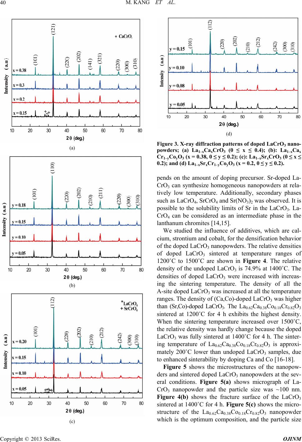 M. KANG ET AL. 40 (a) (b) (c) (d) Figure 3. X-ray diffraction patterns of doped LaCrO3 nano- powders; (a) La1–xCaxCrO3 (0 ≤ x ≤ 0.4); (b): La1–xCax Cr1–yCoyO3 (x = 0.38, 0 ≤ y ≤ 0.2); (c): La1–xSrxCrO3 (0 ≤ x ≤ 0.2); and (d) La1–xSrxCr1–yCoyO3 (x = 0.2, 0 ≤ y ≤ 0.2). pends on the amount of doping precursor. Sr-doped La- CrO3 can synthesize homogeneous nanopowders at rela- tively low temperature. Additionally, secondary phases such as LaCrO4, SrCrO4 and Sr(NO3)2 was observed. It is possible to the solubility limits of Sr in the LaCrO3. La- CrO4 can be considered as an intermediate phase in the lanthanum chromites [14,15]. We studied the influence of additives, which are cal- cium, strontium and cobalt, for the densification behavior of the doped LaCrO3 nanopowders. The relative densities of doped LaCrO3 sintered at temperature ranges of 1200˚C to 1500˚C are shown in Figure 4. The relative density of the undoped LaCrO3 is 74.9% at 1400˚C. The densities of doped LaCrO3 were increased with increas- ing the sintering temperature. The density of all the A-site doped LaCrO3 was increased at all the temperature ranges. The density of (Ca,Co)-doped LaCrO3 was higher than (Sr,Co)-doped LaCrO3. The La0.62Ca0.38Co 0.18Cr0.82O3 sintered at 1200˚C for 4 h exhibits the highest density. When the sintering temperature increased over 1500˚C, the relative density was hardly change because the doped LaCrO3 was fully sintered at 1400˚C for 4 h. The sinter- ing temperature of La0.62Ca0.38Co0.18Cr0.82O3 is approxi- mately 200˚C lower than undoped LaCrO3 samples, due to enhanced sinterability by doping Ca and Co [16-18]. Figure 5 shows the microstructures of the nanopow- ders and sintered doped LaCrO3 nanopowders at the sev- eral conditions. Figure 5(a) shows micrograph of La- CrO3 nanopowder and the particle size was ~100 nm. Figure 4(b) shows the fracture surface of the LaCrO3 sintered at 1400˚C for 4 h. Figure 5(c) shows the micro- structure of the La0.62Ca0.38Co0.18Cr0.82O3 nanopowder which is the optimum composition, and the particle size Copyright © 2013 SciRes. OJINM 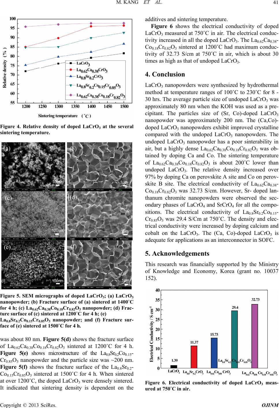 M. KANG ET AL. 41 Figure 4. Relative density of doped LaCrO3 at the several sintering temperature. 100nm (a) 1μm (b) 100nm (c) 1μm (d) 100nm (e) 1μm (f) Figure 5. SEM micrographs of doped LaCrO3; (a) LaCrO3 nanopowder; (b) Fracture surface of (a) sintered at 1400˚C for 4 h; (c) La0.62Ca0.38Co0.18Cr0.82O3 nanopowder; (d) Frac- ture surface of (c) sintered at 1200˚C for 4 h; (e) La0.8Sr0.2Co0.15Cr0.85O3 nanopowder; and (f) Fracture sur- face of (e) sintered at 1500˚C for 4 h. was about 80 nm. Figure 5(d) shows the fracture surface of La0.62Ca0.38Co0.18Cr0.82O3 sintered at 1200˚C for 4 h. Figure 5(e) shows microstructure of the La0.8Sr0.2Co0.15- Cr0.85O3 nanopowder and the particle size was ~200 nm. Figure 5(f) shows the fracture surface of the La0.8Sr0.2- Co0.15Cr0.85O3 sintered at 1500˚C for 4 h. When sintered at over 1200˚C, the doped LaCrO3 were densely sintered. It indicated that sintering density is dependent on the additives and sintering temperature. Figure 6 shows the electrical conductivity of doped LaCrO3 measured at 750˚C in air. The electrical conduc- tivity increased in all the doped LaCrO3. The La0.62Ca0.38- Co0.18Cr0.82O3 sintered at 1200˚C had maximum conduc- tivity of 32.73 S/cm at 750˚C in air, which is about 30 times as high as that of undoped LaCrO3. 4. Conclusion LaCrO3 nanopowders were synthesized by hydrothermal method at temperature ranges of 100˚C to 230˚C for 8 - 30 hrs. The average particle size of undoped LaCrO3 was approximately 80 nm when the KOH was used as a pre- cipitant. The particles size of (Sr, Co)-doped LaCrO3 nanopowder was approximately 200 nm. The (Ca,Co)- doped LaCrO3 nanopowders exhibit improved crystalline compared with the undoped LaCrO3 nanopowders. The undoped LaCrO3 nanopowder has a poor sinterability in air, but a highly dense La0.62Ca0.38Co0.18Cr0.82O3 was ob- tained by doping Ca and Co. The sintering temperature of La0.62Ca0.38Co0.18Cr0.82O3 is about 200˚C lower than undoped LaCrO3. The relative density increased over 97% by doping Ca on perovskite A site and Co on perov- skite B site. The electrical conductivity of La0.62Ca0.38- Co0.18Cr0.82O3 was 32.73 S/cm. However, Sr- doped lan- thanum chromite nanopowders were observed the sec- ondary phases of LaCrO4 and SrCrO4 for all the compo- sitions. The electrical conductivity of La0.8Sr0.2Co0.15- Cr0.85O3 was 29.4 S/Cm at 750˚C. The density and elec- trical conductivity were increased by doping calcium and cobalt on the LaCrO3. The (Ca, Co)-doped LaCrO3 is adequate for applications as an interconnector in SOFC. 5. Acknowledgements This research was financially supported by the Ministry of Knowledge and Economy, Korea (grant no. 10037 152). Figure 6. Electrical conductivity of doped LaCrO3 meas- ured at 750˚C in air. Copyright © 2013 SciRes. OJINM 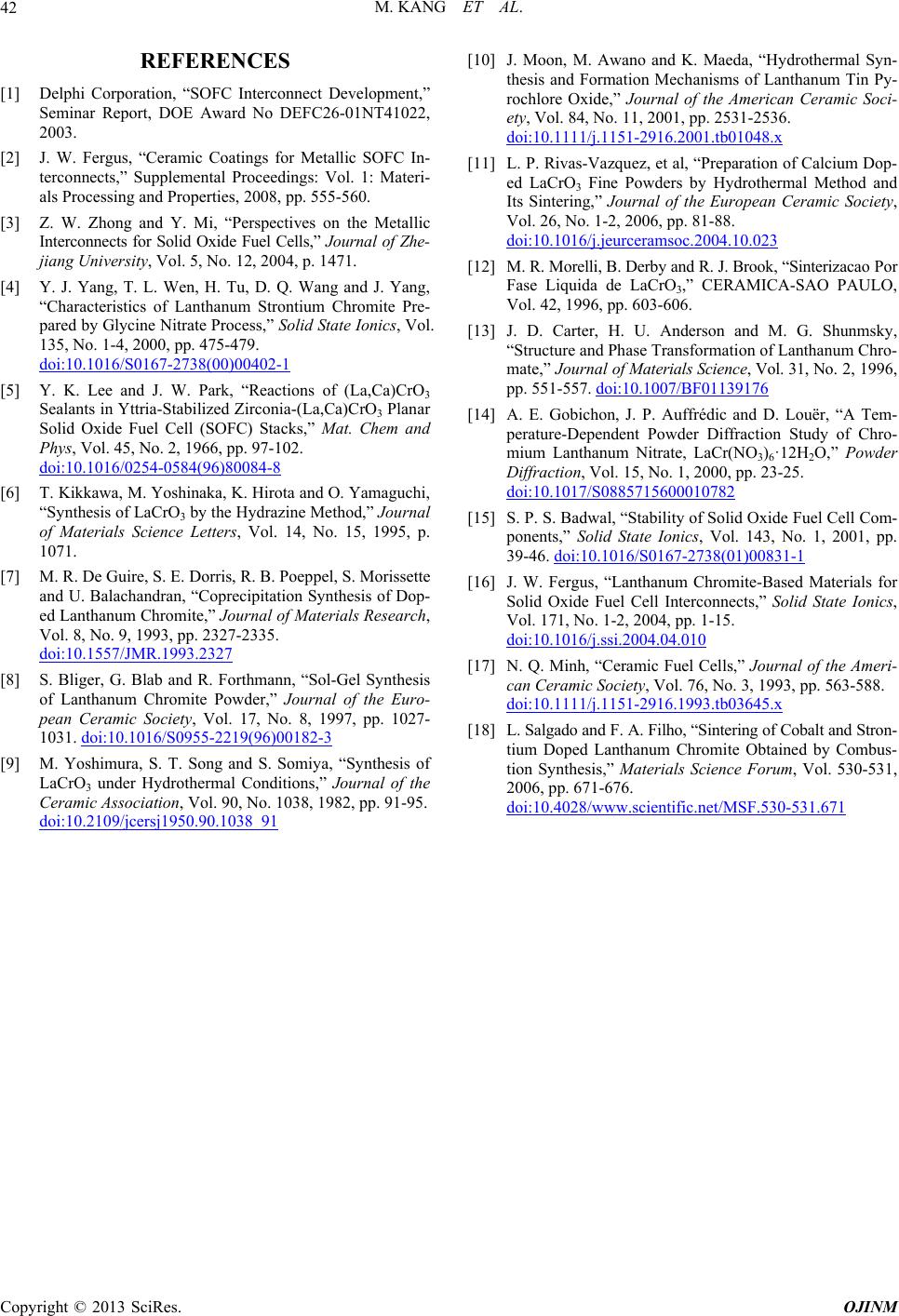 M. KANG ET AL. Copyright © 2013 SciRes. OJINM 42 REFERENCES [1] Delphi Corporation, “SOFC Interconnect Development,” Seminar Report, DOE Award No DEFC26-01NT41022, 2003. [2] J. W. Fergus, “Ceramic Coatings for Metallic SOFC In- terconnects,” Supplemental Proceedings: Vol. 1: Materi- als Processing and Properties, 2008, pp. 555-560. [3] Z. W. Zhong and Y. Mi, “Perspectives on the Metallic Interconnects for Solid Oxide Fuel Cells,” Journal of Zhe- jiang University, Vol. 5, No. 12, 2004, p. 1471. [4] Y. J. Yang, T. L. Wen, H. Tu, D. Q. Wang and J. Yang, “Characteristics of Lanthanum Strontium Chromite Pre- pared by Glycine Nitrate Process,” Solid State Ionics, Vol. 135, No. 1-4, 2000, pp. 475-479. doi:10.1016/S0167-2738(00)00402-1 [5] Y. K. Lee and J. W. Park, “Reactions of (La,Ca)CrO3 Sealants in Yttria-Stabilized Zirconia-(La,Ca)CrO3 Planar Solid Oxide Fuel Cell (SOFC) Stacks,” Mat. Chem and Phys, Vol. 45, No. 2, 1966, pp. 97-102. doi:10.1016/0254-0584(96)80084-8 [6] T. Kikkawa, M. Yoshinaka, K. Hirota and O. Yamaguchi, “Synthesis of LaCrO3 by the Hydrazine Method,” Journal of Materials Science Letters, Vol. 14, No. 15, 1995, p. 1071. [7] M. R. De Guire, S. E. Dorris, R. B. Poeppel, S. Morissette and U. Balachandran, “Coprecipitation Synthesis of Dop- ed Lanthanum Chromite,” Journal of Materials Research, Vol. 8, No. 9, 1993, pp. 2327-2335. doi:10.1557/JMR.1993.2327 [8] S. Bliger, G. Blab and R. Forthmann, “Sol-Gel Synthesis of Lanthanum Chromite Powder,” Journal of the Euro- pean Ceramic Society, Vol. 17, No. 8, 1997, pp. 1027- 1031. doi:10.1016/S0955-2219(96)00182-3 [9] M. Yoshimura, S. T. Song and S. Somiya, “Synthesis of LaCrO3 under Hydrothermal Conditions,” Journal of the Ceramic Association, Vol. 90, No. 1038, 1982, pp. 91-95. doi:10.2109/jcersj1950.90.1038_91 [10] J. Moon, M. Awano and K. Maeda, “Hydrothermal Syn- thesis and Formation Mechanisms of Lanthanum Tin Py- rochlore Oxide,” Journal of the American Ceramic Soci- ety, Vol. 84, No. 11, 2001, pp. 2531-2536. doi:10.1111/j.1151-2916.2001.tb01048.x [11] L. P. Rivas-Vazquez, et al, “Preparation of Calcium Dop- ed LaCrO3 Fine Powders by Hydrothermal Method and Its Sintering,” Journal of the European Ceramic Society, Vol. 26, No. 1-2, 2006, pp. 81-88. doi:10.1016/j.jeurceramsoc.2004.10.023 [12] M. R. Morelli, B. Derby and R. J. Brook, “Sinterizacao Por Fase Liquida de LaCrO3,” CERAMICA-SAO PAULO, Vol. 42, 1996, pp. 603-606. [13] J. D. Carter, H. U. Anderson and M. G. Shunmsky, “Structure and Phase Transformation of Lanthanum Chro- mate,” Journal of Materials Science, Vol. 31, No. 2, 1996, pp. 551-557. doi:10.1007/BF01139176 [14] A. E. Gobichon, J. P. Auffrédic and D. Louër, “A Tem- perature-Dependent Powder Diffraction Study of Chro- mium Lanthanum Nitrate, LaCr(NO3)6·12H2O,” Powder Diffraction, Vol. 15, No. 1, 2000, pp. 23-25. doi:10.1017/S0885715600010782 [15] S. P. S. Badwal, “Stability of Solid Oxide Fuel Cell Com- ponents,” Solid State Ionics, Vol. 143, No. 1, 2001, pp. 39-46. doi:10.1016/S0167-2738(01)00831-1 [16] J. W. Fergus, “Lanthanum Chromite-Based Materials for Solid Oxide Fuel Cell Interconnects,” Solid State Ionics, Vol. 171, No. 1-2, 2004, pp. 1-15. doi:10.1016/j.ssi.2004.04.010 [17] N. Q. Minh, “Ceramic Fuel Cells,” Journal of the Ameri- can Ceramic Society, Vol. 76, No. 3, 1993, pp. 563-588. doi:10.1111/j.1151-2916.1993.tb03645.x [18] L. Salgado and F. A. Filho, “Sintering of Cobalt and Stron- tium Doped Lanthanum Chromite Obtained by Combus- tion Synthesis,” Materials Science Forum, Vol. 530-531, 2006, pp. 671-676. doi:10.4028/www.scientific.net/MSF.530-531.671 |