

Paper Menu >>
Journal Menu >>
 Optics and Photonics Journal, 2013, 3, 225-228 http://dx.doi.org/10.4236/opj.2013.33036 Published Online July 2013 (http://www.scirp.org/journal/opj) Pressure Sensor Based on Mechanically Induced LPFG in Novel MSM Fiber Structure Sunita Ugale, Vivekanand Mishra Department of Electronics and Communication Engineering, S. V. National Institute of Technology, Surat, India Email: [email protected] Received January 1, 2013; revised February 12, 2013; accepted February 20, 2013 Copyright © 2013 Sunita Ugale, Vivekanand Mishra. This is an open access article distributed under the Creative Commons Attribu- tion License, which permits unrestricted use, distribution, and reproduction in any medium, provided the original work is properly cited. ABSTRACT We have proposed and demonstrated experimentally a novel and simple pressure sensor based on mechanically induced long period optical fiber gratings. We report here for the first time to our knowledge the characterization of mechani- cally induced long period fiber gratings in novel multimode-singlemode-multimode fiber structure. The MLPFG in- duced in single mode fiber and multimode fibers are studied separately and the results are compared with MLPFG in- duced in MSM fiber structure. MLPFG in MSM structure has much greater sensitivity. We have obtained maximum transmission loss peak of around 18 dB, and the sensitivity of pressure sensor is 8 dB/Kg. Keywords: Mechanically Induced Grating; Pressure Sensor; Sensitivity 1. Introduction Fiber optics sensors based on gratings are still in the de- velopment stage in laboratories and lot of work is needed to be done to promote and develop their use in advanced applications. In-fiber grating sensor technology has be- come one of the most rapidly progressing sensing topics of this decade in the field of optical fiber sensors. These sensors are currently emerging from the laboratory to find practical applications. Rapid progress has been made in both sensor system developments and applications in recent years. The spectral characteristic of Long period optical fiber grating (LPFG) is more flexible as compared to fiber Bragg grating (FBG). LPFG have low insertion loss and low back reflection. It can offer the advantages of abso- lute measurement, high sensitivity, all-fiber in-line, small size, etc. The other advantages of LPFG sensor include simple fabrication and easiness in adjusting the resonant wavelength well within the spectrum of optical source by simply adjusting the grating period. All these attractive features of LPFGs are the strong points to push towards detail study of this device. Because of much longer Pitch Λ (almost 100 times that of FBG) the forward propagat- ing core bounded modes and cladding-bounded modes couple to each other. Therefore there are several resonant peaks depending on the involved number of cladding modes in the interesting wavelength range and the core mode is coupled to several copropagating cladding modes. Many methods have been demonstrated for the fabri- cation of LPFG. The techniques can be divided into two groups: the one that enables the fabrication of permanent gratings, and the other that allows the fabrication of re- versible or mechanically induced gratings, i.e. by remov- ing the external perturbation the grating disappears [1]. As the period of LPFG is of the order of micrometers, it can be induced through microbending using various me- chanical means. The important advantage of this tech- nique over other techniques is that it can be applied to any kind of fiber and is also simple, flexible and low-cost. These are very sensitive to external pressures enabling a good control over their transmission characteristics [2,3]. 2. LPFG Mathematical Model If a periodical pressure is applied on the waveguide, a long period grating is formed owing to the photo elastic effect and the microbending effect. The energy of the core mode LP01 is coupled into that of the cladding mod- es LP1m if the phase matching condition as follows is satisfied [4]. 22 2 co cl eff eff nn (1) where : is the effective index of the core mode, : Is the effective index of cladding mode. co eff ncl eff n C opyright © 2013 SciRes. OPJ 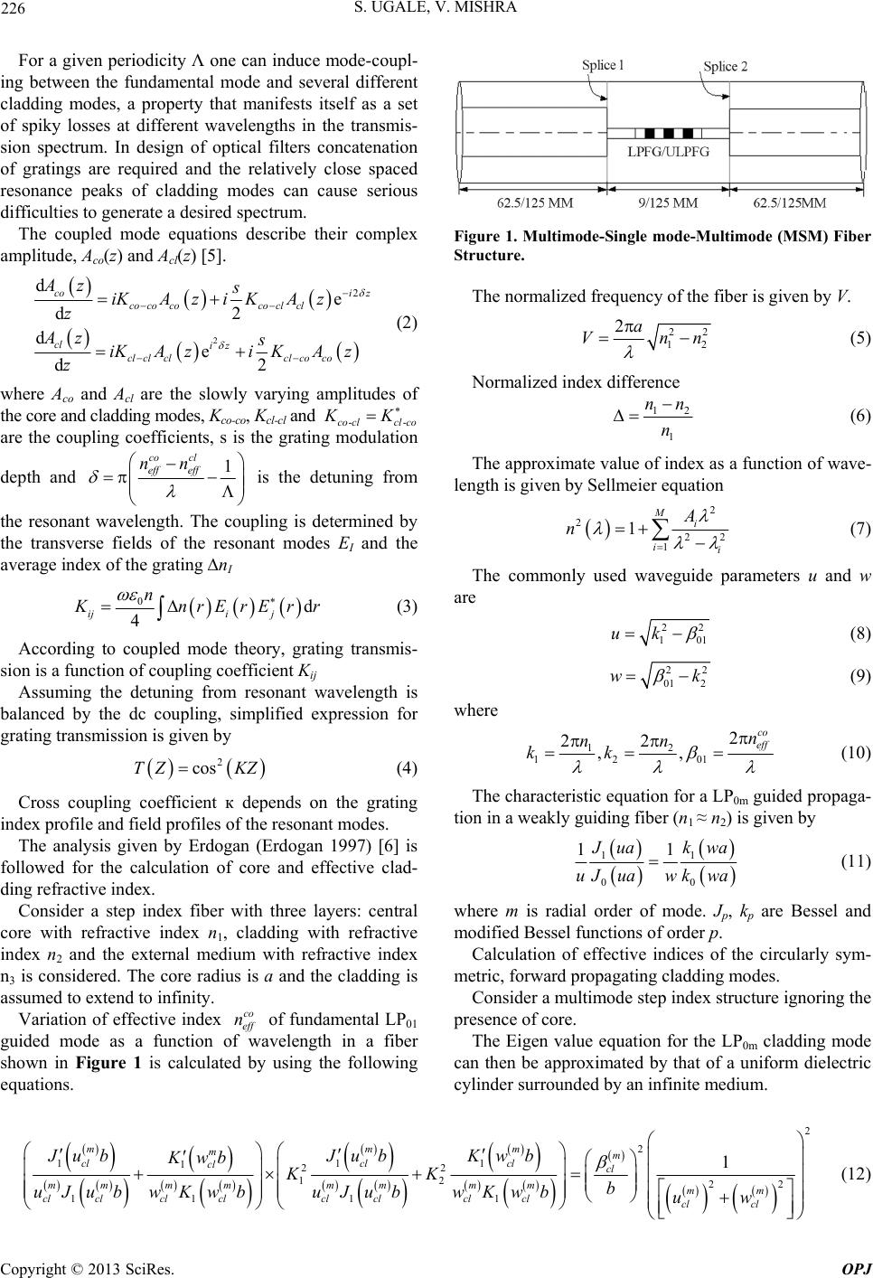 S. UGALE, V. MISHRA 226 For a given periodicity Λ one can induce mode-coupl- ing between the fundamental mode and several different cladding modes, a property that manifests itself as a set of spiky losses at different wavelengths in the transmis- sion spectrum. In design of optical filters concatenation of gratings are required and the relatively close spaced resonance peaks of cladding modes can cause serious difficulties to generate a desired spectrum. The coupled mode equations describe their complex amplitude, Aco(z) and Acl(z) [5]. 2 2 de d2 de d2 co iz co cococo clcl cl iz cl clclcl coco Az s iKAzi KAz z Az s iKAzi KAz z (2) where Aco and Acl are the slowly varying amplitudes of the core and cladding modes, Kco-co, Kcl-cl and --co clclco are the coupling coefficients, s is the grating modulation KK depth and 1 co cl eff eff nn is the detuning from the resonant wavelength. The coupling is determined by the transverse fields of the resonant modes EI and the average index of the grating nI 0d 4 iji j n K nrE rErr (3) According to coupled mode theory, grating transmis- sion is a function of coupling coefficient Kij Assuming the detuning from resonant wavelength is balanced by the dc coupling, simplified expression for grating transmission is given by 2 cosTZ KZ (4) Cross coupling coefficient к depends on the grating index profile and field profiles of the resonant modes. The analysis given by Erdogan (Erdogan 1997) [6] is followed for the calculation of core and effective clad- ding refractive index. Consider a step index fiber with three layers: central core with refractive index n1, cladding with refractive index n2 and the external medium with refractive index n3 is considered. The core radius is a and the cladding is assumed to extend to infinity. Variation of effective index of fundamental LP01 guided mode as a function of wavelength in a fiber shown in Figure 1 is calculated by using the following equations. co eff n Figure 1. Multimode-Single mode-Multimode (MSM) Fiber Structure. The normalized frequency of the fiber is given by V. 22 12 Vn n 2a (5) Normalized index difference 12 1 nn n (6) The approximate value of index as a function of wave- length is given by Sellmeier equation 2 2 22 1 1 Mi ii A n (7) The commonly used waveguide parameters u and w are 22 10 uk 1 (8) 22 01 2 w k (9) where 12 12 01 2 22 ,, co eff n nn kk (10) The characteristic equation for a LP0m guided propaga- tion in a weakly guiding fiber (n1 ≈ n2) is given by 11 00 11 J uak wa uJ uawk wa (11) where m is radial order of mode. Jp, kp are Bessel and modified Bessel functions of order p. Calculation of effective indices of the circularly sym- metric, forward propagating cladding modes. Consider a multimode step index structure ignoring the presence of core. The Eigen value equation for the LP0m cladding mode can then be approximated by that of a uniform dielectric cylinder surrounded by an infinite medium. 2 2 111 122 12 22 111 1 1 mmm mm clcl cl cl cl mmm mmmm mmm cl clclclcl clclclcl cl JubJub Kwb Kwb KK b uJub wKwbuJubwKwbuw (12) Copyright © 2013 SciRes. OPJ 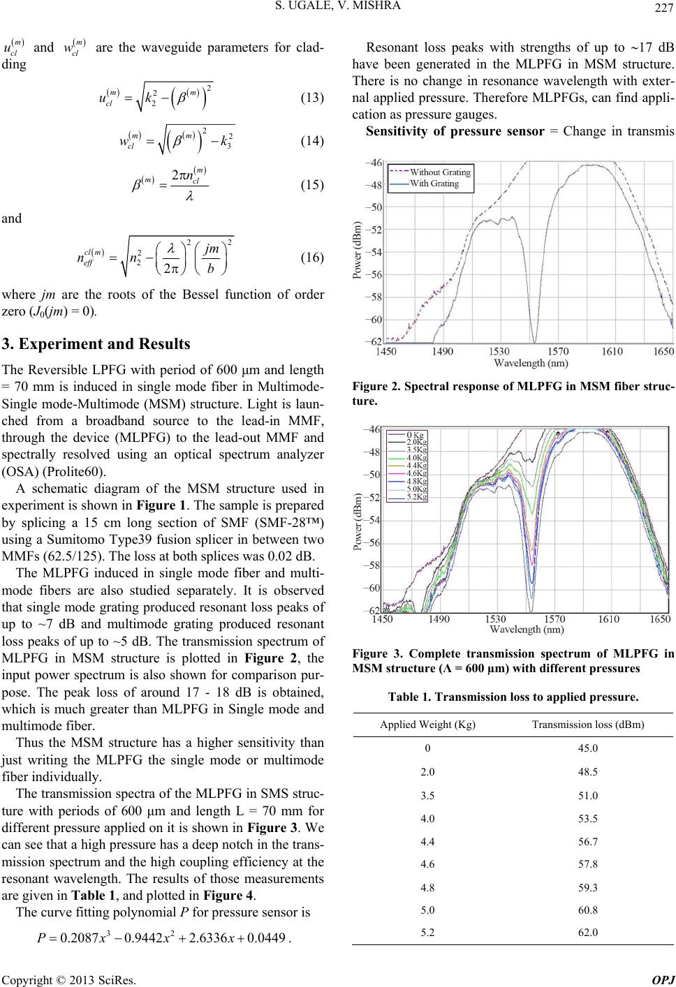 S. UGALE, V. MISHRA 227 m cl u and are the waveguide parameters for clad- ding m cl w 2 2 2 m cl uk m (13) 22 3 mm cl w k (14) 2m mcl n (15) and 22 2 22 cl m eff jm nn b (16) where jm are the roots of the Bessel function of order zero (J0(jm) = 0). 3. Experiment and Results The Reversible LPFG with period of 600 μm and length = 70 mm is induced in single mode fiber in Multimode- Single mode-Multimode (MSM) structure. Light is laun- ched from a broadband source to the lead-in MMF, through the device (MLPFG) to the lead-out MMF and spectrally resolved using an optical spectrum analyzer (OSA) (Prolite60). A schematic diagram of the MSM structure used in experiment is shown in Figure 1. The sample is prepared by splicing a 15 cm long section of SMF (SMF-28™) using a Sumitomo Type39 fusion splicer in between two MMFs (62.5/125). The loss at both splices was 0.02 dB. The MLPFG induced in single mode fiber and multi- mode fibers are also studied separately. It is observed that single mode grating produced resonant loss peaks of up to ~7 dB and multimode grating produced resonant loss peaks of up to ~5 dB. The transmission spectrum of MLPFG in MSM structure is plotted in Figure 2, the input power spectrum is also shown for comparison pur- pose. The peak loss of around 17 - 18 dB is obtained, which is much greater than MLPFG in Single mode and multimode fiber. Thus the MSM structure has a higher sensitivity than just writing the MLPFG the single mode or multimode fiber individually. The transmission spectra of the MLPFG in SMS struc- ture with periods of 600 μm and length L = 70 mm for different pressure applied on it is shown in Figure 3. We can see that a high pressure has a deep notch in the trans- mission spectrum and the high coupling efficiency at the resonant wavelength. The results of those measurements are given in Table 1, and plotted in Figure 4. The curve fitting polynomial P for pressure sensor is 32 0.20870.94422.6336 0.0449Px xx. Resonant loss peaks with strengths of up to 17 dB have been generated in the MLPFG in MSM structure. There is no change in resonance wavelength with exter- nal applied pressure. Therefore MLPFGs, can find appli- cation as pressure gauges. Sensitivity of pressure sensor = Change in transmis Figure 2. Spectral response of MLPFG in MSM fiber struc- ture. Figure 3. Complete transmission spectrum of MLPFG in MSM structure (Λ = 600 µm) with different pressures Table 1. Transmission loss to applied pressure. Applied Weight (Kg) Transmission loss (dBm) 0 45.0 2.0 48.5 3.5 51.0 4.0 53.5 4.4 56.7 4.6 57.8 4.8 59.3 5.0 60.8 5.2 62.0 Copyright © 2013 SciRes. OPJ 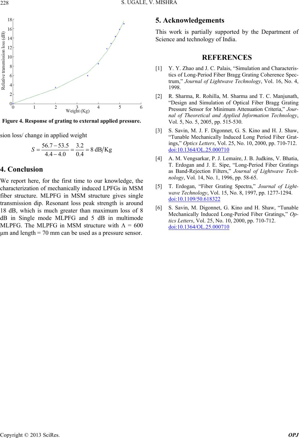 S. UGALE, V. MISHRA 228 Figure 4. Response of grating to external applied pressure. sion loss/ change in applied weight 56.7 53.53.28dB Kg 4.4 4.00.4 S 4. Conclusion We report here, for the first time to our knowledge, the characterization of mechanically induced LPFGs in MSM fiber structure. MLPFG in MSM structure gives single transmission dip. Resonant loss peak strength is around 18 dB, which is much greater than maximum loss of 8 dB in Single mode MLPFG and 5 dB in multimode MLPFG. The MLPFG in MSM structure with = 600 μm and length = 70 mm can be used as a pressure sensor. 5. Acknowledgements This work is partially supported by the Department of Science and technology of India. REFERENCES [1] Y. Y. Zhao and J. C. Palais, “Simulation and Characteris- tics of Long-Period Fiber Bragg Grating Coherence Spec- trum,” Journal of Lightwave Technology, Vol. 16, No. 4, 1998. [2] R. Sharma, R. Rohilla, M. Sharma and T. C. Manjunath, “Design and Simulation of Optical Fiber Bragg Grating Pressure Sensor for Minimum Attenuation Criteria,” Jour- nal of Theoretical and Applied Information Technology, Vol. 5, No. 5, 2005, pp. 515-530. [3] S. Savin, M. J. F. Digonnet, G. S. Kino and H. J. Shaw, “Tunable Mechanically Induced Long Period Fiber Grat- ings,” Optics Letters, Vol. 25, No. 10, 2000, pp. 710-712. doi:10.1364/OL.25.000710 [4] A. M. Vengsarkar, P. J. Lemaire, J. B. Judkins, V. Bhatia, T. Erdogan and J. E. Sipe, “Long-Period Fiber Gratings as Band-Rejection Filters,” Journal of Lightwave Tech- nology, Vol. 14, No. 1, 1996, pp. 58-65. [5] T. Erdogan, “Fiber Grating Spectra,” Journal of Light- wave Technology, Vol. 15, No. 8, 1997, pp. 1277-1294. doi:10.1109/50.618322 [6] S. Savin, M. Digonnet, G. Kino and H. Shaw, “Tunable Mechanically Induced Long-Period Fiber Gratings,” Op- tics Letters, Vol. 25, No. 10, 2000, pp. 710-712. doi:10.1364/OL.25.000710 Copyright © 2013 SciRes. OPJ |