

Paper Menu >>
Journal Menu >>
 International Journal of Geosciences, 2013, 4, 844-849 http://dx.doi.org/10.4236/ijg.2013.45078 Published Online July 2013 (http://www.scirp.org/journal/ijg) Influence of Recycled Aggregate Composites on the Factor of Safety of Earthen Structures Md. Zakaria Hossain Department of Environmental Science and Technology, Mie University, Mie, Japan Email: [email protected] Received April 19, 2013; revised May 23, 2013; accepted June 22, 2013 Copyright © 2013 Md. Zakaria Hossain. This is an open access article distributed under the Creative Commons Attribution License, which permits unrestricted use, distribution, and reproduction in any medium, provided the original work is properly cited. ABSTRACT In this study, six composite reinforcements such as cement composite made of Abandoned Cell Husks (ASH), Stones, Wood chips, Concrete and Bricks have been used along with control specimen. It is known that the material used in earth reinforcement applications must be safe against tension failure and adhesion failure for its effective utilization in the field and reliable design of earth structures. Single type of material can provide limited reinforcement capability in reinforced earth structures due to its low frictional resistance and poor cohesion. For an optimal response, therefore, composite reinforcement, that fulfils both the requirements such as possess adequate tensile strength and adequate fric- tional resistance, is getting considerable attention. Slope stability analyses containing six types of reinforcement have been performed. Stability of the slope has been quantified using minimum factor of safety corresponding to critical slip surface. It was observed that the composite reinforcement whose surface treated by brick aggregate enhanced the factor of safety significantly. The paper also depicted the design aids of reinforced slope in terms of embedding lengths and spacing of reinforcements. Keywords: Earthen Structures; Stability Factor; Composite Reinforcement; Recycled Aggregate 1. Introduction The embankments, dams, foundations, abutments and all earth fill structures must be stable under all static and dynamic loadings during construction and on-service [1]. Collapse in earth fill embankments occurs at the critical slip surface when the factor of safety (Fs) decreases due to weathering, erosion, seepage, changes of surface and subsurface water, earthquake and many other natural calamities [2-8]. In order to obtain a necessary factor of safety for a given slope, it must be reinforced to improve the stability above the safety level. There are various earth reinforcing materials worldwide. Among them, the geosynthetic or geogrid are conventional reinforcements that are commonly used for earth reinforcement applica- tions. It is evident that the conventional reinforcements, used for reinforcing earth fill structure, contain only one type of material such as geogrid, geosynthetic or wire mesh etc. The material used in earth reinforcement ap- plications must be safe against tension failure and adhe- sion failure for its effective utilization in thefield and safe design of earth structures [9-11]. For a given situation, single type of material can provide limited reinforcement capability in reinforced earth structures due to its low frictional resistance and poor cohesion. For an optimal response, therefore, different types of reinforcement that fulfils both the requirements such as possess adequate tensile strength and adequate frictional resistance, is get- ting considerable attention lately [12,13]. Stability analysis is usually performed to find out the factor of safety of the earth fill structures [14-18]. Refer- ring to Figure 1, the composite reinforcement provides resisting force thereby increases the factor of safety of the fill embankments. In this paper, slope stability analy- ses containing six types of composite reinforcement have been performed. Thin reinforced-mortar composite con- sisting of evenly distributed fine mesh as the reinforce- ment and cement-sand mortar as the matrix showed en- hanced performance because of its synergetic action of mesh with mortar and mortar with soil [19-23]. Consid- ering the facts given above, slope stability analyses for reinforced embankments containing various types of composite reinforcements have been conducted using simplified method. Six composite materials were used Surface treatment for five types of composite specimens were made by using Abandoned Cell Husks (ASH), Stones, Wood chips, Concrete and Bricks. The control C opyright © 2013 SciRes. IJG 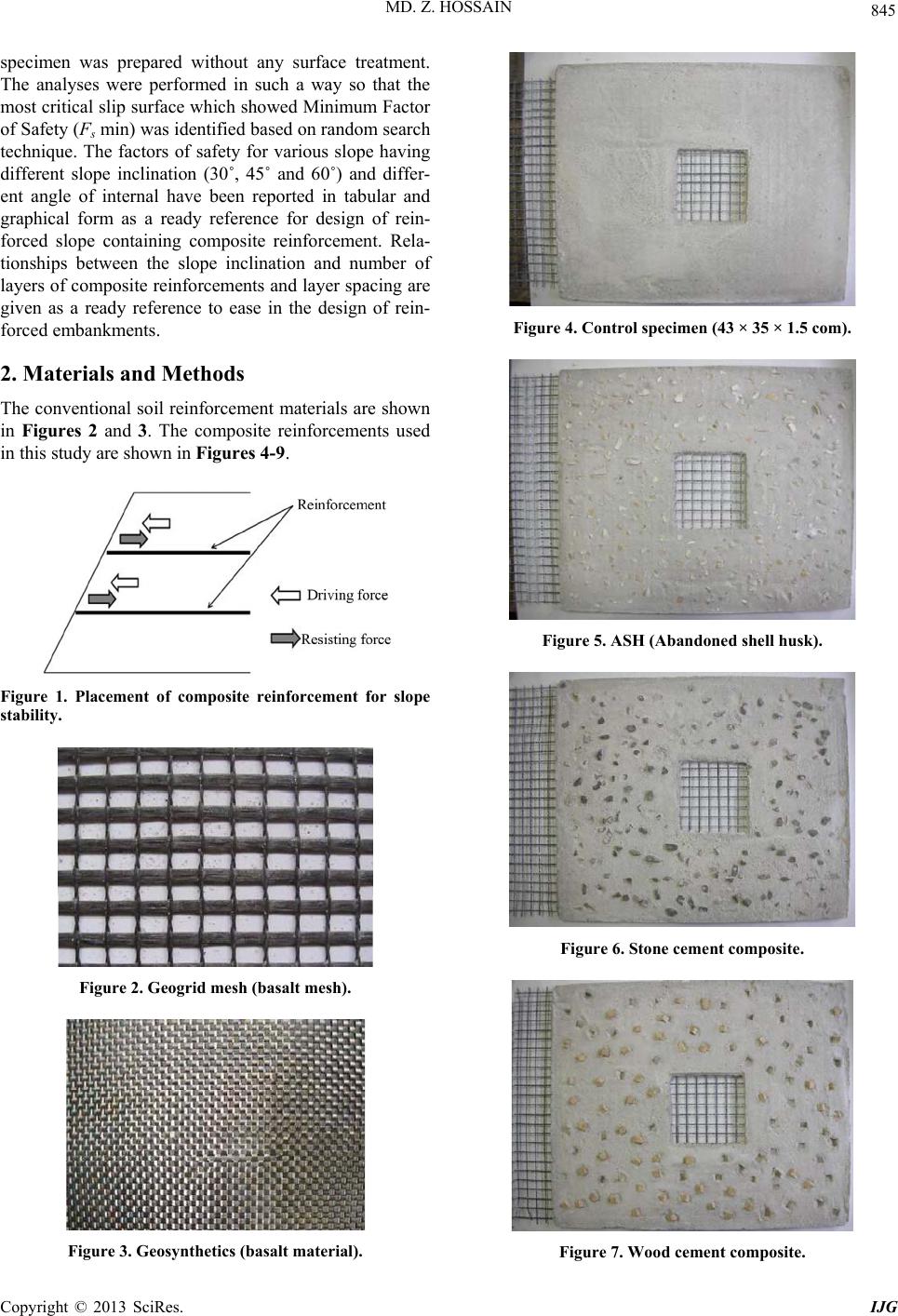 MD. Z. HOSSAIN 845 specimen was prepared without any surface treatment. The analyses were performed in such a way so that the most critical slip surface which showed Minimum Factor of Safety (Fs min) was identified based on random search technique. The factors of safety for various slope having different slope inclination (30˚, 45˚ and 60˚) and differ- ent angle of internal have been reported in tabular and graphical form as a ready reference for design of rein- forced slope containing composite reinforcement. Rela- tionships between the slope inclination and number of layers of composite reinforcements and layer spacing are given as a ready reference to ease in the design of rein- forced embankments. 2. Materials and Methods The conventional soil reinforcement materials are shown in Figures 2 and 3. The composite reinforcements used in this study are shown in Figures 4-9. Figure 1. Placement of composite reinforcement for slope stability. Figure 2. Geogrid mesh (basalt mesh). Figure 3. Geosynthetics (basalt material). Figure 4. Control specimen (43 × 35 × 1.5 com). Figure 5. ASH (Abandoned shell husk). Figure 6. Stone cement composite. Figure 7. Wood cement composite. Copyright © 2013 SciRes. IJG 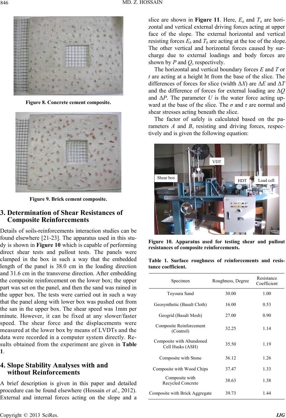 MD. Z. HOSSAIN 846 Figure 8. Concrete cement composite. Figure 9. Brick cement composite. 3. Determination of Shear Resistances of Composite Reinforcements Details of soils-reinforcements interaction studies can be found elsewhere [21-23]. The apparatus used in this stu- dy is shown in Figure 10 which is capable of performing direct shear tests and pullout tests. The panels were clamped in the box in such a way that the embedded length of the panel is 38.0 cm in the loading direction and 31.6 cm in the transverse direction. After embedding the composite reinforcement on the lower box; the upper part was set on the panel, and then the sand was rained in the upper box. The tests were carried out in such a way that the panel along with lower box was pushed out from the san in the upper box. The shear speed was 1mm per minute. However, it can be fixed at any slower/faster speed. The shear force and the displacements were measured at the lower box by means of LVDTs and the data were recorded in a computer system directly. Re- sults obtained from the experiment are given in Table 1. 4. Slope Stability Analyses with and without Reinforcements A brief description is given in this paper and detailed procedure can be found elsewhere (Hossain et al., 2012). External and internal forces acting on the slope and a slice are shown in Figure 11. Here, Ea and Ta are hori- zontal and vertical external driving forces acting at upper face of the slope. The external horizontal and vertical resisting forces Eb and Tb are acting at the toe of the slope. The other vertical and horizontal forces caused by sur- charge due to external loadings and body forces are shown by P and Q, respectively. The horizontal and vertical boundary forces E and T or t are acting at a height ht from the base of the slice. The differences of forces for slice (width ΔX) are ΔE and ΔT and the difference of forces for external loading are ΔQ and ΔP. The parameter U is the water force acting up- ward at the base of the slice. The σ and τ are normal and shear stresses acting beneath the slice. The factor of safely is calculated based on the pa- rameters A and B, resisting and driving forces, respec- tively and is given the following equation: VDT Shear boxHDT Load cell Figure 10. Apparatus used for testing shear and pullout resistances of composite reinforcements. Table 1. Surface roughness of reinforcements and resis- tance coefficient. Specimen Roughness, Degree Resistance Coefficient Toyoura Sand 30.00 1.00 Geosynthetic (Basalt Cloth) 16.00 0.53 Geogrid (Basalt Mesh) 27.00 0.90 Composite Reinforcement (Control) 32.25 1.14 Composite with Abandoned Cell Husks (ASH) 35.50 1.19 Composite with Stone 36.12 1.26 Composite with Wood Chips37.47 1.33 Composite with Recycled Concrete 38.63 1.38 Composite with Brick Aggregate39.73 1.44 Copyright © 2013 SciRes. IJG 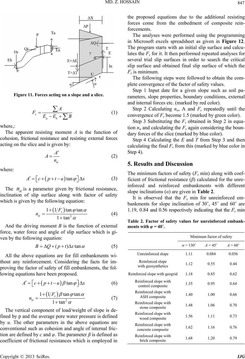 MD. Z. HOSSAIN 847 Figure 11. Forces acting on a slope and a slice. s F ab A EE B (1) where,: The apparent resisting moment A is the function of cohesion, frictional resistance and resisting external forces acting on the slice and is given by: A An tan (2) where: A cp tu x n (3) The is a parameter given by frictional resistance, inclination of slip surface along with factor of safety which is given by the following equation: 2 tantan 1tan s 11F n ()tanptx (4) And the driving moment B is the function of external force, water force and angle of slip surface which is gi- ven by the following equation: BQ tan (5) All the above equations are for fill embankments wi- thout any reinforcement. Considering the facts for im- proving the factor of safety of fill embankments, the fol- lowing equations have been proposed. A cpt ux (6) 2 tantan an 11 1t s F n (7) The vertical component of load/weight of slope is de- fined by p and the average pore water pressure is defined by u. The other parameters in the above equations are conventional such as cohesion and angle of internal fric- tion are defined by c and φ. The parameter β is defined as coefficient of frictional resistances which is employed in the proposed equations due to the additional resisting forces come from the embedment of composite rein- forcements. The analyses were performed using the programming in Microsoft excels spreadsheet as given in Figure 12. The program starts with an initial slip surface and calcu- lates the Fs for it. It then performed repeated analyses for several trial slip surfaces in order to search the critical slip surface and obtained final slip surface of which the Fs is minimum. The following steps were followed to obtain the com- plete convergence of the factor of safety values. Step 1 Input date for a given slope such as soil pa- rameters, slope properties, boundary conditions, external and internal forces etc. (marked by red color). Step 2 Calculating nα, A and Fs repeatedly until the convergence of Fs become 1.5 (marked by green color). Step 3 Substituting the Fs obtained in Step 2 in equa- tion nα and calculating the Fs again considering the boun- dary forces of the slice (marked by blue color). Step 4 Calculating the E and T from Step 3 and then calculating the final Fs from this (marked by blue color in Step 4). 5. Results and Discussion The minimum factors of safety (Fs min) along with coef- ficient of frictional resistance (β) calculated for the unre- inforced and reinforced embankments with different slope inclinations (α) are given in Table 2. It is observed that the Fs min for unreinforced em- bankments for slope inclination of 30˚, 45˚ and 60˚ are 1.19, 0.84 and 0.56 respectively indicating that the Fs min Table 2. Factor of safety values for unreinforced embank- ments with φ = 40˚. Minimum factor of safety α = 130˚ Α = 45˚ Α = 60˚ Unreinforced slope 1.11 0.084 0.056 Reinforced slope with geosynthetics 1.12 0.55 0.44 Reinforced slope with geogrid1.18 0.85 0.62 Reinforced slope with control composite 1.35 0.95 0.64 Reinforced slope with ASH composite 1.40 1.00 0.66 Reinforced slope with stone composite 1.48 1.06 0.70 Reinforced slope with wood composite 1.56 1.11 0.73 Reinforced slope with concrete composite 1.62 1.16 0.76 Reinforced slope with brick composite 1.68 1.20 0.79 Copyright © 2013 SciRes. IJG 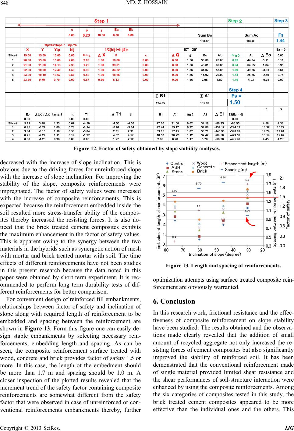 MD. Z. HOSSAIN IJG 848 Step 3 o Fs 1.44 Step 2 Sum BoSum A 130.85 187.83 Step 1 cφEa Eb 0.00 0.23 18.00 0.000.00 Y tp=Xi/slope r Ytp -Yb XYYtp hij1/2(hij1+hij2)r 19.00 15.00 15.000.00tan X Pc 57°20’ Slice# Ea = 0 Q 20.0013.0015.002.00 2.00 1.0018.000.000.00 21.0011.8014.132.33 1.20 1.0039.010.000.00 22.0010.9012.401.50 0.90 1.0034.520.000.00 23.0010.1010.670.57 0.80 1.0018.650.000.00 23.609.70 9.70 0.00 0.67 0.60 5.130.000.00 φBo A'o n Ao 11.5636.00 28.080.63 44.34 21.5646.81 60.850.94 64.55 31.5631.07 53.861.09 49.36 41.5614.92 29.091.14 25.56 51.56 2.05 4.801.19 4.03 Step 4 B1 A1 Fs = 124.05 185.99 1. 50 Eo Eo / Eo 0.0 0 5.115.11 1.846.95 -3.31 3.64 -2.89 0.75 -0.75 0.00 x tant ht T1 T1 t1B1 A'1 n A1 E1 E1(Ea = 0) 0.000.00 0.000.00 Slice#5.11 3.48 1.33 0.67-4.50-4.50-4.5027.0021.060.6234.19-86.95-86.95 16.95-0.741.090.78-8.14-3.64 -3.6442.4455.17 0.9259.88-157.17-244.12 23.64 -3.10 1.180.50 -5.842.312.3133.1557.451.0753.71-145.90-390.02 30.75 -2.27 1.110.19 -1.274.574.5718.5736.221.1232.42-89.50-479.52 40.00-1.260.98 0.00 0.001.27 2.122.90 6.78 1.17 5.78-16.38-495.90 4.56 4.38 16.37 15.72 19.79 19.01 13.19 12.67 4.45 4.28 Figure 12. Factor of safety obtained by slope stability analyses. decreased with the increase of slope inclination. This is obvious due to the driving forces for unreinforced slope with the increase of slope inclination. For improving the stability of the slope, composite reinforcements were impregnated. The factor of safety values were increased with the increase of composite reinforcements. This is expected because the reinforcement embedded inside the soil resulted more stress-transfer ability of the compos- ites thereby increased the resisting forces. It is also no- ticed that the brick treated cement composites exhibits the maximum enhancement in the factor of safety values. This is apparent owing to the synergy between the two materials in the hybrids such as synergetic action of mesh with mortar and brick treated mortar with soil. The time effects of different reinforcements have not been studies in this present research because the data noted in this paper were obtained by short term experiment. It is rec- ommended to perform long term durability tests of dif- ferent reinforcements for better comparison. Figure 13. Length and spacing of reinforcements. optimization attempts using surface treated composite rein- forcement are obviously warranted. For convenient design of reinforced fill embankments, relationships between factor of safety and inclination of slope along with required length of reinforcement to be embedded and spacing between the reinforcement are shown in Figure 13. Form this figure one can easily de- sign stable embankments by selecting necessary rein- forcements, embedding length and spacing. As can be seen, the composite reinforcement surface treated with wood, concrete and brick provides factor of safety 1.5 or more. In this case, the length of the embedment should be more than 1.7 m and spacing should be 1.0 m. A closer inspection of the plotted results revealed that the increment trend of the safety factor containing composite reinforcements are somewhat different from the safety factor that were observed in case of unreinforced or con- ventional reinforcements embankments thereby, further 6. Conclusion In this research work, frictional resistance and the effec- tiveness of composite reinforcement on slope stability have been studied. The results obtained and the observa- tions made clearly revealed that the addition of small amount of recycled aggregate not only increased the re- sisting forces of cement composites but also significantly improved the stability of reinforced soil. It has been demonstrated that the conventional reinforcement made of single material provided limited shear resistance and the shear performances of soil-structure interaction were enhanced by using the composite reinforcements. Among the six categories of composites tested in this study, the brick treated cement composites appeared to be more effective than the individual ones and the others. This Copyright © 2013 SciRes.  MD. Z. HOSSAIN 849 study further suggests that the simple soil-structure in- teraction tests can effectively be used in characterization of shear behaviour of the surface treated mesh-reinforced cement composites. 7. Acknowledgements The present study is partly supported by the Research Grant No. 22580271 with funds from Grants-in-Aid for Scientific Research, Japan. The writers gratefully acknowledge these supports. Any opinions, findings, and conclusions ex- pressed in this paper are those of the authors and do not necessarily reflect the views of the sponsor. REFERENCES [1] M. Z. Hossain and M. Z. Islam, “Embankments Failure in Bangladesh: Causes and Recommendations,” Indian Jour- nal of Power and River Valley Development, Vol. 60, No. 10, 2010, pp. 166-171. [2] M. Z. Hossain, “A Study on Thin Cementitious Compos- ite (TCC) Materials for Soil Reinforcement Applica- tions,” Australian Journal of Agricultural Engineering, Vol. 1, No. 4, 2010, pp. 153-159. [3] M. T. Islam, M. Z. Hossain and M. Ishida, “Analyses of Cost Comparison of Slope Protection Method between Japan and Bangladesh,” International Journal of Envi- ronment, Vol. 2, No. 1, 2012, pp. 73-79. [4] M. T. Islam, M. Z. Hossain and M. Ishida, “Designing Vertical and Horizontal Frame Structure for Slope Protec- tion,” Australian Journal of Agricultural Engineering, Vol. 3, No. 2, 2012, pp. 70-74. [5] M. B. Hossain, T. Sakai and M. Z. Hossain, “River Em- bankment and Bank Failure: A Study on Geotechnical Characteristics and Stability Analysis,” American Journal of Environmental Sciences, Vol. 7, No. 2, 2011, pp. 102- 107. doi:10.3844/ajessp.2011.102.107 [6] M. Z. Hossain, K. Ito, T. Sakai and M. B. Hossain, “Sim- plified Slope Stability Analysis for Earth Fill Structure with Various Types of Reinforcements,” GEOSYNTHE- TICS ASIA 2012, 5th Asian Regional Conference on Geo- synthetics, Bangkok, 13-16 December 2012, pp. 617- 623. [7] J. M. Duncan, “State of the Art: Limit Equilibrium and Finite-Element Analysis of Slopes,” Journal of Geotech- nical Engineering, ASCE, Vol. 122, No. 7, 1996, pp. 577- 596. doi:10.1061/(ASCE)0733-9410(1996)122:7(577) [8] D. G. Fredlund and J. Krahn, “Comparison of Slope Sta- bility Methods of Analysis,” Canadian Geotechnical Jour- nal, Vol. 14, No. 3, 1977, pp. 429-439. doi:10.1139/t77-045 [9] M. Z. Hossain, “A Comparative Study on Pullout Behav- ior of Reinforcements for Effective Design of Reinforced Soil Structures,” International Agricultural Engineering Journal, Vol. 16, No. 3, 2007, pp. 123-138. [10] M. Z. Hossain, “A Potential Composite Material for Pos- sible Applications in Earth Reinforcement,” Agricultural Engineering International, CIGRE Journal, Vol. 10, No. 36, 2008, pp. 1-18. [11] M. Z. Hossain, “Pullout Response of Cement Composite Members Embedded in Soil,” ACI Materials Journal, Vol. 105, No. 1, 2008, pp. 16-124. [12] M. Z. Hossain and S. Inoue, “Determinate Method for Slope Stability Analysis of Earthen Structures,” International Agricultural Engineering Journal, Vol. 16, No. 1, 2007, pp. 15-24. [13] M. Z. Hossain and T. Sakai, “A Study on Pullout Behav- ior of Reinforcement Due to Variation of Water Content of Soil,” Agricultural Engineering International, CIGRE Journal, Vol. 9, No. 89, 2007, pp. 1-15. [14] N. Janbu, “Slope Stability Computation,” In: R. C. Hirs- chfeld and S. J. Poulos, Eds., Embankment-Dam Engi- neering, Casagrande, Krieger Publishing Company, Flo- rida, 1987, pp. 47-86. [15] N. R. Morgenstern and V. E. Price, “The Analysis of the Stability of General Slip Surface,” Geotechnique, Vol. 15, No. 1, 1965, pp. 79-93. doi:10.1680/geot.1965.15.1.79 [16] E. Spencer, “A Method of Analysis of the Stability of Embankments Assuming Parallel Inter-Slice Forces,” Geo- technique, Vol. 17, No. 1, 1967, pp. 11-26. doi:10.1680/geot.1967.17.1.11 [17] S. G. Wright and J. M. Duncan, “Limit Equilibrium Sta- bility Analyses for Reinforced Slopes,” TRB Paper No. 910441, Transportation Research Board, Washington DC, 1991. [18] S. G. Wright, F. G. Kulhawy and J. M. Duncan, “Accu- racy of Equilibrium Slope Stability Analysis,” Journal of Soil Mechanics and Foundations Division, ASCE, Vol. 99, No. 10, 1973, pp. 783-791. [19] M. Z. Hossain, “Development of a Small-Scale Universal Apparatus for Evaluating Soil-Structure Interaction,” Jour- nal of Civil Engineering and Architecture, Vol. 5, No. 4, 2011, pp. 314-321. [20] K. Ito, M. Z. Hossain and T. Sakai, “Development of Design Charts for Reinforced Embankment Using Excel Spreadsheet Slope Stability Analysis,” Proceedings of the 1st International Conferenec on Geotechnique, Construc- tion Materials and Environment, Mie, 21-23 November 2011, pp. 183-186. [21] M. Z. Hossain and H. Inagaki, “Dilatancy Behavior of Soil-Structure Interfaces for Farm Roads and Embank- ments,” Australian Journal of Agricultural Engineering, Southern Cross Publisher, Vol. 2, No. 1, 2011, pp. 12-17. [22] M. B. Hossain, M. Z. Hossain and T. Sakai, “Interaction Properties of Geosynthetic with Different Backfill Soils,” International Journal of Geosciences, Vol. 3, No. 5, 2012, pp. 1033-1039. doi:10.4236/ijg.2012.35104 [23] M. B. Hossain, M. Z. Hossain and T. Sakai, “Evaluation of Sand/Geosynthetic Interface Behavior for Earth Rein- forcement,” International Journal of Geotechnical Engi- neering, Vol. 7, No. 3, 2013, pp. 452-465. Copyright © 2013 SciRes. IJG |