

Paper Menu >>
Journal Menu >>
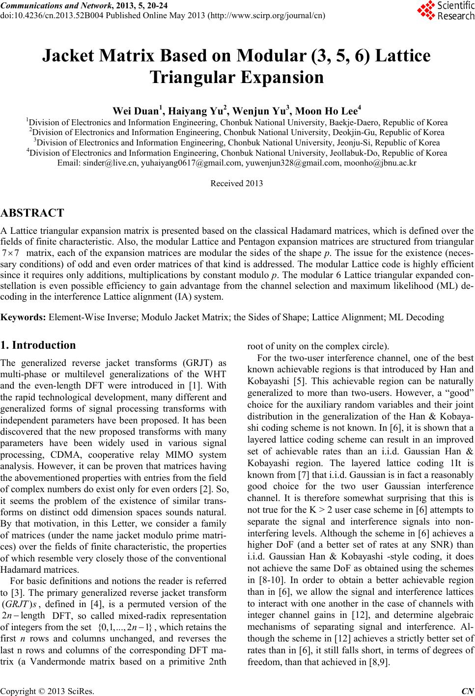 Communications and Network, 2013, 5, 20-24 doi:10.4236/cn.2013.52B004 Published Online May 2013 (http://www.scirp.org/journal/cn) Jacket Matrix Based on Modular (3, 5, 6) Lattice Triangular Expansion Wei Duan1, Haiya ng Yu2, Wenjun Yu3, Moon Ho Lee4 1Division of Electronics and Information Engineering, Chonbuk National University, Baekje-Daero, Republic of Korea 2Division of Electronics and Information Engineering, Chonbuk National University, Deokjin-Gu, Republic of Korea 3Division of Electronics and Information Engineering, Chonbuk National University, Jeonju-Si, Republic of Korea 4Division of Electronics and Information Engineering, Chonbuk National University, Jeollabuk-Do, Republic of Korea Email: [email protected], yuha[email protected], [email protected], [email protected] Received 2013 ABSTRACT A Lattice triangular expansion matrix is presented based on the classical Hadamard matrices, which is defined over the fields of finite characteristic. Also, the modular Lattice and Pentagon expansion matrices are structured from triangular matrix, each of the expansion matrices are modular the sides of the shape p. The issue for the existence (neces- sary conditions) of odd and even order matrices of that kind is addressed. The modular Lattice code is highly efficient since it requires only additions, multiplications by constant modulo p. The modular 6 Lattice triangular expanded con- stellation is even possible efficiency to gain advantage from the channel selection and maximum likelihood (ML) de- coding in the interference Lattice alignment (IA) system. 77 Keywords: Element-Wise Inverse; Modulo Jacket Matrix; the Sides of Shape; Lattice Alignment; ML Decoding 1. Introduction The generalized reverse jacket transforms (GRJT) as multi-phase or multilevel generalizations of the WHT and the even-length DFT were introduced in [1]. With the rapid technological development, many different and generalized forms of signal processing transforms with independent parameters have been proposed. It has been discovered that the new proposed transforms with many parameters have been widely used in various signal processing, CDMA, cooperative relay MIMO system analysis. However, it can be proven that matrices having the abovementioned properties with entries from the field of complex numbers do exist only for even orders [2]. So, it seems the problem of the existence of similar trans- forms on distinct odd dimension spaces sounds natural. By that motivation, in this Letter, we consider a family of matrices (under the name jacket modulo prime matri- ces) over the fields of finite characteristic, the properties of which resemble very closely th ose of the conventio nal Ha damard matrices. For basic definitions and notions the reader is referred to [3]. The primary generalized reverse jacket transform , defined in [4], is a permuted version of the DFT, so called mixed-radix representation of integers from the set , which retains the first n rows and columns unchanged, and reverses the last n rows and columns of the corresponding DFT ma- trix (a Vandermonde matrix based on a primitive 2nth root of unity on the complex circle). (GRJT s 2lenn For the two-user interference channel, one of the best known achievable regions is that introduced by Han and Kobayashi [5]. This achievable region can be naturally generalized to more than two-users. However, a “good” choice for the auxiliary random variables and their joint distribution in the generalization of the Han & Kobaya- shi coding sche me is not known. In [6], it is shown th at a layered lattice coding scheme can result in an improved set of achievable rates than an i.i.d. Gaussian Han & Kobayashi region. The layered lattice coding 1It is known from [7] that i.i.d. Gaussian is in fact a reasonably good choice for the two user Gaussian interference channel. It is therefore somewhat surprising that this is not true for the K > 2 user case sch eme in [6] attempts to separate the signal and interference signals into non- interfering levels. Alth ough the scheme in [6] achieves a higher DoF (and a better set of rates at any SNR) than i.i.d. Gaussian Han & Kobayashi -style coding, it does not achieve the same DoF as obtained using the schemes in [8-10]. In order to obtain a better achievable region than in [6], we allow the signal and interference lattices to interact with one another in the case of channels with integer channel gains in [12], and determine algebraic mechanisms of separating signal and interference. Al- though the sche me in [12] achieves a strictly b etter set of rates than in [6], it still falls short, in terms of degrees of freedom, than that achieved in [8,9]. ) gth {0,1,...,2 1}n Copyright © 2013 SciRes. CN 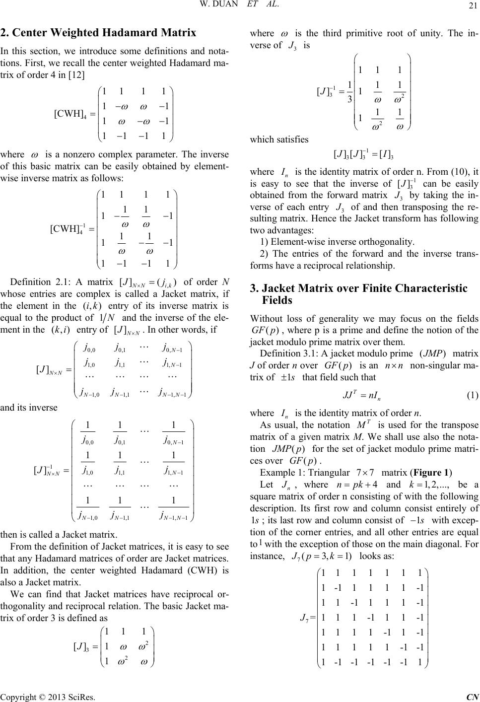 W. DUAN ET AL. 21 2. Center Weighted Hadamard Matrix In this section, we introduce some definitions and nota- tions. First, we recall the center weighted Hadamard ma- trix of orde r 4 i n [12] 4 111 1 11 [CWH] 11 1111 where is a nonzero complex parameter. The inverse of this basic matrix can be easily obtained by element- wise inverse matrix as follows: 1 4 111 1 11 11 [CWH] 11 11 11 11 Definition 2.1: A matrix , []( ) N Nik J j of order N whose entries are complex is called a Jacket matrix, if the element in the entry of its inverse matrix is equal to the product of (, )ik 1N and the inverse of the ele- ment in the entry of (,)ki [] N N J. In other words, if 0,00,10, 1 1,01,11, 1 1,01,11,1 [] N N NN NN NN jj j jj j J jj j and its inverse 0,00,10, 1 11,01,11, 1 1,01,11, 1 11 1 11 1 [] 11 1 N N NN NN NN jj j jj j J jj j then is called a Jacket matrix. From the definition of Jacket matrices, it is easy to see that any Hadamard matrices of order are Jacket matrices. In addition, the center weighted Hadamard (CWH) is also a Jacket matrix. We can find that Jacket matrices have reciprocal or- thogonality and reciprocal relation. The basic Jacket ma- trix of orde r 3 i s de fi ned as 2 32 11 1 [] 1 1 J where is the third primitive root of unity. The in- verse of 3 J is 1 32 2 11 1 111 [] 1 311 1 J which satisfies 1 33 [][] [] 3 J JI where n I is th e identity matrix of order n. From (10), it is easy to see that the inverse of 1 3 [] J can be easily obtained from the forward matrix 3 J by taking the in- verse of each entry 3 J of and then transposing the re- sulting matrix. Hence th e Jacket transform has following two advantages: 1) Element-wise inverse orthogonality. 2) The entries of the forward and the inverse trans- forms have a reciprocal relationship. 3. Jacket Matrix over Finite Characteristic Fields Without loss of generality we may focus on the fields , where p is a prime and define the notion of the jacket modulo prime matrix over them. ()GF p Definition 3.1: A jacket modulo prime () J MP matrix J of order n over is an non-singular ma- trix of ()GF pnn 1 s that field such that Tn J JnI (1) where n I is the identity matrix of order n. As usual, the notation T M is used for the transpose matrix of a given matrix M. We shall use also the nota- tion () J MPp (GF for the set of jacket modulo prime matri- ces over . )p Example 1: Triangular matrix (Figure 1) 77 Let n J , where 4npk and be a square matrix of order n consisting of with the following description. Its first row and column consist entirely of 1,2,...,k 1 s ; its last row and column consist o f 1 s with excep- tion of the corner entries, and all other entries are equal to1with the exception of those on the main d iagonal. For instance, 7(3Jp ,1)k looks as: 7 1111111 1-11111-1 1 1-1 111-1 =11 1-11 1-1 1111-11-1 11111-1-1 1-1-1-1-1-11 J Copyright © 2013 SciRes. CN 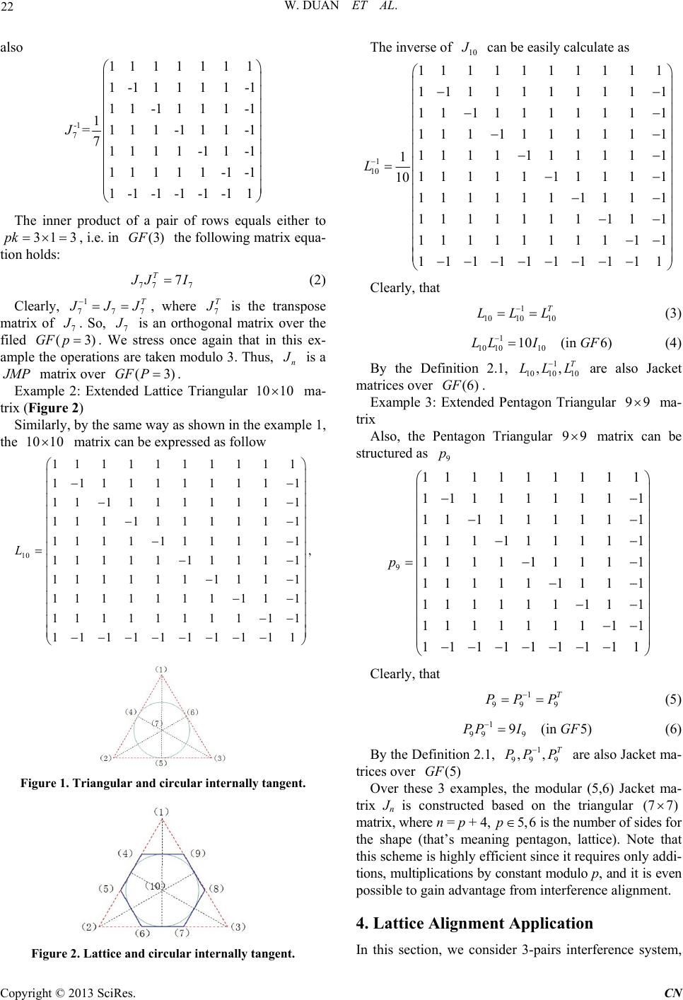 W. DUAN ET AL. 22 also -1 7 1111111 1-11111-1 1 1-1 111-1 1 =11 1-11 1-1 71111-11-1 11111-1-1 1-1-1-1-1-11 J The inner product of a pair of rows equals either to , i.e. in the following matrix equa- tion holds: 31 3pk (3)GF 77 7 7 T J JI (2) Clearly, 7 1 77 T J JJ , where 7 T J is the transpose matrix of 7 J . So, 7 J is an orthogonal matrix over the filed . We stress once again that in this ex- ample the operations are taken modulo 3. Thus, (3)pGF n J is a J MP matrix over . (3)GF P Example 2: Extended Lattice Triangular 10 10 ma- trix (Figure 2) Similarly, by the same way as shown in the example 1, the matrix can be ex pressed as follow 10 10 10 1111111111 111111111 1 11 11111111 111 1111111 1111 111111 , 11111 11111 111111 1111 1111111 111 11111111 11 1111111111 L Figure 1. Triangular and circular internally tangent. Figure 2. Lattice and circular internally tangent. The inverse of 10 J can be easily calculate as 1 10 1111111111 111111111 1 11 1111111 1 111 111111 1 11 1 111 1 1 11 1 11 1 1111 1 11 10 111111 111 1 1111111 11 1 11111111 11 1111111111 L Clearly, that 1 10 10 10 T LLL (3) 1 10 1010 10(in 6)LL IGF 1T (4) By the Definition 2.1, are also Jacket matrices over . 10 1010 ,,LLL (6)GF Example 3: Extended Pentagon Triangular 99 ma- trix Also, the Pentagon Triangular matrix can be structured as 99 9 p 9 111111111 11111111 1 11 111111 1 111 11111 1 11 1 111 1 11 11 1 1 111 11 111111 11 1 1111111 11 111111111 p Clearly, that 1 99 9 T PPP (5) 1 99 9 9(in5PP IGF 1T ) (6) By the Definition 2.1, are also Jacket ma- trices over 99 9 ,,PP P (5)GF Over these 3 examples, the modular (5,6) Jacket ma- trix Jn is constructed based on the triangular (7 7) matrix, where n = p + 4, 5,6p is the number of sides for the shape (that’s meaning pentagon, lattice). Note that this scheme is highly efficient since it requires on ly addi- tions, multiplications by constant modulo p, and it is even possible to gain advantage from interference alignment. 4. Lattice Alignment Application In this section, we consider 3-pairs interference system, Copyright © 2013 SciRes. CN 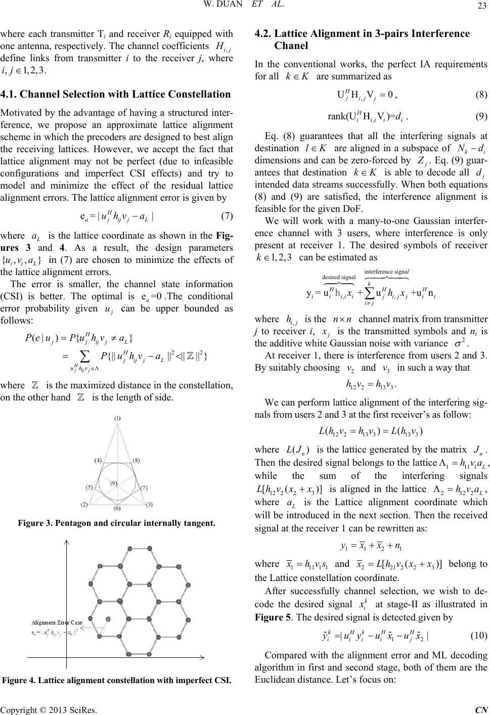 W. DUAN ET AL. 23 where each transmitter Ti and receiver Ri equipped with one antenna, respectively. The channel coefficients ,ij H define links from transmitter i to the receiver j, where . ,1,2,3ij 4.1. Channel Selection with Lattice Constellation Motivated by the advantage of having a structured inter- ference, we propose an approximate lattice alignment scheme in which the precoders are designed to best align the receiving lattices. However, we accept the fact that lattice alignment may not be perfect (due to infeasible configurations and imperfect CSI effects) and try to model and minimize the effect of the residual lattice alignment errors. The lattice alignment error is given by e=| | H ajijjL uhv a (7) where L a , }a is the lattice coordinate as shown in the Fig- ures 3 and 4. As a result, the design parameters ii L in (7) are chosen to minimize the effects of the lattice alignment errors. {,uv The error is smaller, the channel state information (CSI) is better. The optimal is .The conditional error probability given e=0 a j u can be upper bounded as follows: 22 (| ){} {|||||||| } H jijj H jjijjL H jijj L uhv Pe uPuhva Puhv a where is the maximized distance in the cons tellation , on the other ha nd is the length of side. Figure 3. Pentagon and circular internally tangent. Figure 4. Lattice alignment constellation with imperfect CSI. 4.2. Lattice Alignment in 3-pairs Interference Chanel In the conventional works, the perfect IA requirements for all kK are summarized as , UHV0, H jijj (8) , rank(UHV)=. H iiiii d (9) Eq. (8) guarantees that all the interfering signals at destination lK are aligned in a subspace of ki Nd dimensions and can be zero-forced by j Z . Eq. (9) guar- antees that destination kK is able to decode all j d intended data streams successfully. When both equations (8) and (9) are satisfied, the interference alignment is feasible for the given DoF. We will work with a many-to-one Gaussian interfer- ence channel with 3 users, where interference is only present at receiver 1. The desired symbols of receiver 1, 2,3k can be estimated as interference signa desired signal ,, y=u+u+u n l k HH iiiii jijji ij xhx hH i where ,ij is the nnh channel matrix from transmitter j to receiver i, j x is the transmitted symbols and ni is the additive white Gaussian noise with variance 2 . At receiver 1, there is interference from users 2 and 3. By suitably choosing and in such a way that 2 v3 v 12213 3.hv hv We can perform lattice align ment of the int erfering sig- nals from users 2 and 3 at the first receiver’s as follow: 12213 313 3 ()(LhvhvLhv) where is the lattice generated by the matrix () n LJ n J . Then the desired sign al belongs to the lattice1111 L hva , while the sum of the interfering signals 12 223 [(x x)Lh v] is aligned in the lattice 2122 L hv a, where L a is the Lattice alignment coordinate which will be introduced in the next section. Then the received signal at the receiver 1 can be rewritten as: 112 yxxn 1 where 11111 x hvs and 221223 [( )] x Lh vxx belong to the Lattice constellation coordinate. After successfully channel selection, we wish to de- code the desired signal k i x at stage-II as illustrated in Figure 5. The desired signal is detected given by 1 || kHkHH iiii j yuyuxux 2 (10) Compared with the alignment error and ML decoding algorithm in first and second stage, both of them are the Euclidean distance. Let’s focus on: Copyright © 2013 SciRes. CN 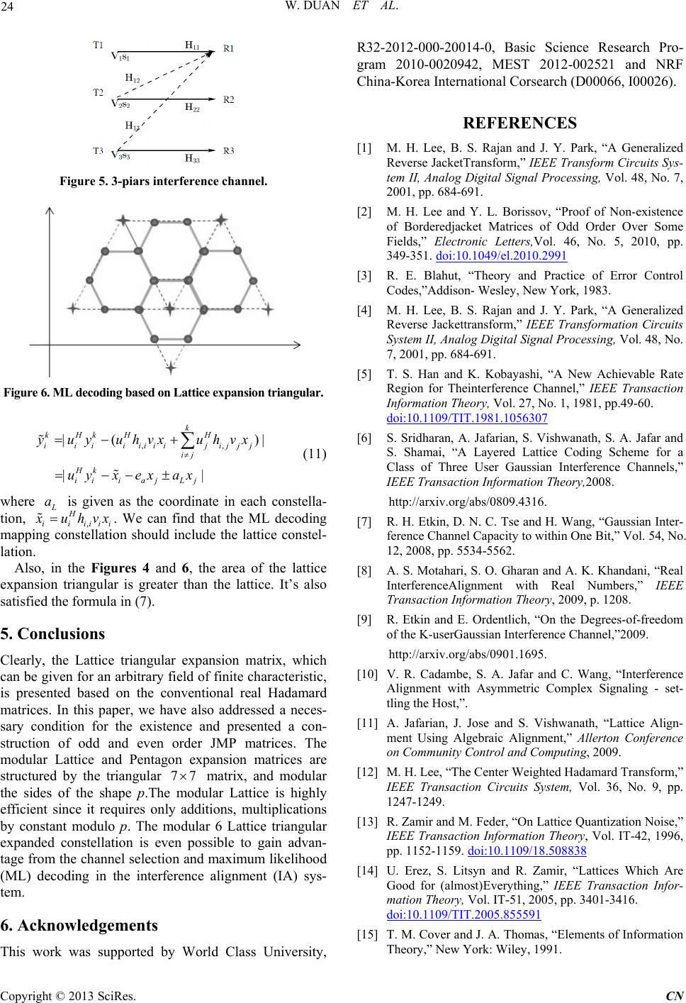 W. DUAN ET AL. Copyright © 2013 SciRes. CN 24 Figure 5. 3-piars interference channel. Figure 6. ML decoding based on Lattice expansion triangular. ,, |( || k kHkH H iiiiiiii jijjj ij Hk iii ajLj yuyuhvxuhvx uyx exax )| (11) where L a is given as the coordinate in each constella- tion, ,i H iiiii x uhvx . We can find that the ML decoding mapping constellation should include the lattice constel- lation. Also, in the Figures 4 and 6, the area of the lattice expansion triangular is greater than the lattice. It’s also satisfied the formula in (7). 5. Conclusions Clearly, the Lattice triangular expansion matrix, which can be given for an arbitrary field of finite characteristic, is presented based on the conventional real Hadamard matrices. In this paper, we have also addressed a neces- sary condition for the existence and presented a con- struction of odd and even order JMP matrices. The modular Lattice and Pentagon expansion matrices are structured by the triangular 77 matrix, and modular the sides of the shape p.The modular Lattice is highly efficient since it requires only additions, multiplications by constant modulo p. The modular 6 Lattice triangular expanded constellation is even possible to gain advan- tage from the channel selection and maximum likelihood (ML) decoding in the interference alignment (IA) sys- tem. 6. Acknowledgements his work was supported by World Class University, R32-2012-000-20014-0, Basic Science Research Pro- gram 2010-0020942, MEST 2012-002521 and NRF China-Korea International Corsearch (D00066, I00026). REFERENCES [1] M. H. Lee, B. S. Rajan and J. Y. Park, “A Generalized Reverse JacketTransform,” IEEE Transform Circuits Sys- tem II, Analog Digital Signal Processing, Vol. 48, No. 7, 2001, pp. 684-691. [2] M. H. Lee and Y. L. Borissov, “Proof of Non-existence of Borderedjacket Matrices of Odd Order Over Some Fields,” Electronic Letters,Vol. 46, No. 5, 2010, pp. 349-351. doi:10.1049/el.2010.2991 [3] R. E. Blahut, “Theory and Practice of Error Control Codes,”Addison- Wesley, New York, 1983. [4] M. H. Lee, B. S. Rajan and J. Y. Park, “A Generalized Reverse Jackettransform,” IEEE Transformation Circuits System II, Analog Digital Signal Processing, Vol. 48, No. 7, 2001, pp. 684-691. [5] T. S. Han and K. Kobayashi, “A New Achievable Rate Region for Theinterference Channel,” IEEE Transaction Information Theory, Vol. 27, No. 1, 1981, pp.49-60. doi:10.1109/TIT.1981.1056307 [6] S. Sridharan, A. Jafarian, S. Vishwanath, S. A. Jafar and S. Shamai, “A Layered Lattice Coding Scheme for a Class of Three User Gaussian Interference Channels,” IEEE Transaction Information Theory,2008. http://arxiv.org/abs/0809.4316. [7] R. H. Etkin, D. N. C. Tse and H. Wang, “Gaussian Inter- ference Channel Capacity to within One Bit,” Vol. 54, No. 12, 2008, pp. 5534-5562. [8] A. S. Motahari, S. O. Gharan and A. K. Khandani, “Real InterferenceAlignment with Real Numbers,” IEEE Transaction Information Theory, 2009, p. 1208. [9] R. Etkin and E. Ordentlich, “On the Degrees-of-freedom of the K-userGaussian Interference Channel,”2009. http://arxiv.org/abs/0901.1695. [10] V. R. Cadambe, S. A. Jafar and C. Wang, “Interference Alignment with Asymmetric Complex Signaling - set- tling the Host,”. [11] A. Jafarian, J. Jose and S. Vishwanath, “Lattice Align- ment Using Algebraic Alignment,” Allerton Conference on Community Control and Computing, 2009. [12] M. H. Lee, “The Center Weighted Hadamard Transform,” IEEE Transaction Circuits System, Vol. 36, No. 9, pp. 1247-1249. [13] R. Zamir and M. Feder, “On Lattice Quantization Noise,” IEEE Transaction Information Theory, Vol. IT-42, 1996, pp. 1152-1159. doi:10.1109/18.508838 [14] U. Erez, S. Litsyn and R. Zamir, “Lattices Which Are Good for (almost)Everything,” IEEE Transaction Infor- mation Theory, Vol. IT-51, 2005, pp. 3401-3416. doi:10.1109/TIT.2005.855591 [15] T. M. Cover and J. A. T homas, “Elements of Information Theory,” New York: Wiley, 1991. T |