

Paper Menu >>
Journal Menu >>
 Journal of Electromagnetic Analysis and Applications, 2013, 5, 312-315 http://dx.doi.org/10.4236/jemaa.2013.57048 Published Online July 2013 (http://www.scirp.org/journal/jemaa) Finite Element Assisted Numerical Comparison of Single and Two Phase Inductively Coupled Power Transfer Systems* Pratik Raval#, Dariusz Kacprzak, Aiguo Patrick Hu Department of Electrical and Computer Engineering, The University of Auckland, Auckland, New Zealand. Email: #[email protected] Received May 13th, 2013; revised June 13th, 2013; accepted June 21st, 2013 Copyright © 2013 Pratik Raval et al. This is an open access article distributed under the Creative Commons Attribution License, which permits unrestricted use, distribution, and reproduction in any medium, provided the original work is properly cited. ABSTRACT Inductively coupled power transfer systems (ICPT) are becoming ubiquitous in industry. Many such systems are excited with single or multi-phase input current. This leads to increased complexity in comparing such systems when solely using the magnetic frequency analysis. This paper utilizes modern finite element method analysis software to propose a novel software methodology for the numerical comparison of single and two phase ICPT systems as demonstrated on a three dimensional (3D) battery charging system. The sinusoidal magnetic frequency response of a single phase system is compared to the magnetic transient response of a multi-phase cu rrent system by u se of a novel software methodology proposed in this paper. This consists of a transient response analysis to determine compute the resulting magnetic re- sponse over the duration of an input current period on the two phase system. The resulting non-sinusoidal response is then integrated over a whole period to extract the root-mean-square value for comparison with that of a single phase system across a 3D cubic power zone. Keywords: Finite Element Method; Electromagnetics; Magnetics; Induction; Wireless-Power-Transfer 1. Introduction The technique termed inductively coupled power transfer (ICPT) is a wireless-power-transfer technique that trans- fers power across an air-gap by means of magnetic in- duction [1]. This technique removes the inconveniences caused from physical wires by providing power in hard to reach places where conventional direct electrical con- nections are inconven ient, hazardou s, or impossible, low- ers maintenance requirements as there is less wear and tear from wet, dirty, moisturized and hazardous envi- ronments, and provides enhanced safety as it is free of sparking and can be used in potentially explosive atmos- pheres and supports freedom of mechanical movement of any load(s) as opposed to a localized load(s). Naturally, this has led to many ICPT applications including mono- rail systems [2,3], people mover or transportation appli- cations such electric cars, trains and buses [4], biomedi- cal implantation and more recently low power consumer battery charging applications [5]. However, a majority of current such applications largely only support unidirec- tional and/or bidirectional load movement. That is, there is no support for three-dimensional (3D) load movement along orthogonal axes. This is due to a lack of generation of an omnidirectional primary link that provides a 3D power transfer window. This paper uses the developed 3D cage—like primary magnetic structures that compose a unique 3D ICPT system. Furthermore, depending on the application requirements, the primary AC excitation cur- rents in these systems may be applied as single or multi- phase. For analysis, such excitation of primary currents must be numerically computed using advanced modern finite element method (FEM) analysis software as in [6]. The FEM software being used is JMAG designer. This paper proposes a methodology for the numerical comparison of a single and two phase 3D battery charg- ing ICPT system in terms of the resulting magnetic field. 2. Proposed ICPT System The battery charging system operating at 155 kHz is il- lustrated in Figure 1. The power converter inverts a DC input to distribute an A C power transfer window through the primary track coils. Typically, the power converter *The author declares no conflict of interest. #Corresponding author. Copyright © 2013 SciRes. JEMAA 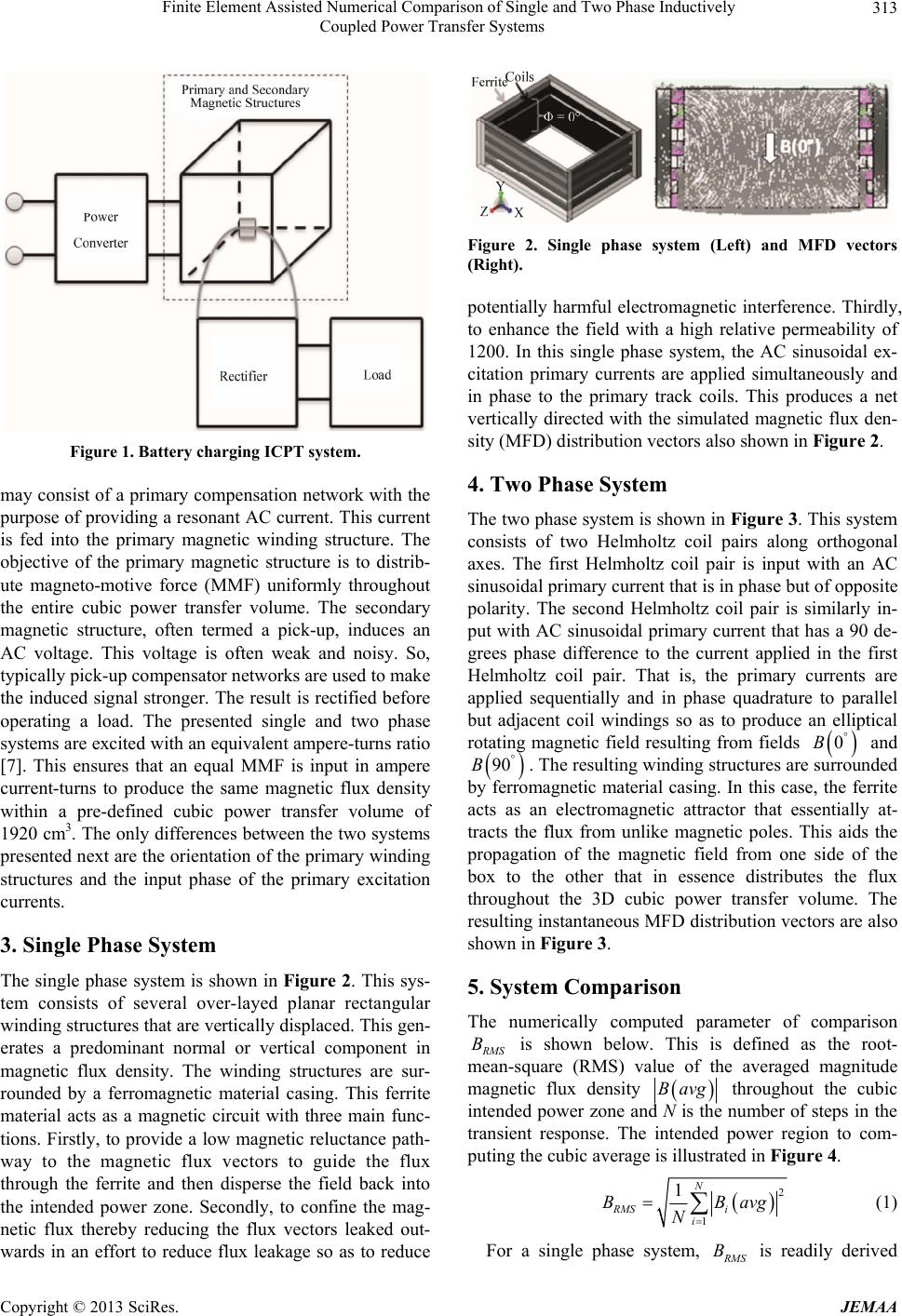 Finite Element Assisted Numerical Comparison of Single and Two Phase Inductively Coupled Power Transfer Systems 313 Figure 1. Battery charging ICPT system. may consist of a p rimary compensation network with the purpose of providing a resonant AC current. This current is fed into the primary magnetic winding structure. The objective of the primary magnetic structure is to distrib- ute magneto-motive force (MMF) uniformly throughout the entire cubic power transfer volume. The secondary magnetic structure, often termed a pick-up, induces an AC voltage. This voltage is often weak and noisy. So, typically pick-up compensator networks are used to make the induced signal stronger. The result is rectified before operating a load. The presented single and two phase systems are excited with an equivalent ampere-turns ratio [7]. This ensures that an equal MMF is input in ampere current-turns to produce the same magnetic flux density within a pre-defined cubic power transfer volume of 1920 cm3. The only differences between the two systems presented next are the orientatio n of the primary winding structures and the input phase of the primary excitation currents. 3. Single Phase System The single phase system is shown in Figure 2. This sys- tem consists of several over-layed planar rectangular winding structures that are vertically displaced. This gen- erates a predominant normal or vertical component in magnetic flux density. The winding structures are sur- rounded by a ferromagnetic material casing. This ferrite material acts as a magnetic circuit with three main func- tions. Firstly, to provide a low magnetic reluctance path- way to the magnetic flux vectors to guide the flux through the ferrite and then disperse the field back into the intended power zone. Secondly, to confine the mag- netic flux thereby reducing the flux vectors leaked out- wards in an effort to reduce flux leakage so as to reduce Figure 2. Single phase system (Left) and MFD vectors (Right). potentially harmful electromagnetic interference. Thirdly, to enhance the field with a high relative permeability of 1200. In this single phase system, the AC sinusoidal ex- citation primary currents are applied simultaneously and in phase to the primary track coils. This produces a net vertically directed with the simulated magnetic flux den- sity (MFD) distribution vectors also shown in Figur e 2. 4. Two Phase System The two phase system is shown in Figure 3. This system consists of two Helmholtz coil pairs along orthogonal axes. The first Helmholtz coil pair is input with an AC sinusoidal primary current that is in phase but of opposite polarity. The second Helmholtz coil pair is similarly in- put with AC sinusoidal primary current that has a 90 de- grees phase difference to the current applied in the first Helmholtz coil pair. That is, the primary currents are applied sequentially and in phase quadrature to parallel but adjacent coil windings so as to produce an elliptical rotating magnetic field resulting from fields 0B and 90B. The resulting winding structures are su rrounded by ferromagnetic material casing. In this case, the ferrite acts as an electromagnetic attractor that essentially at- tracts the flux from unlike magnetic poles. This aids the propagation of the magnetic field from one side of the box to the other that in essence distributes the flux throughout the 3D cubic power transfer volume. The resulting instantan eous MFD distribution vectors are also shown in Figure 3. 5. System Comparison The numerically computed parameter of comparison R MS is shown below. This is defined as the root- mean-square (RMS) value of the averaged magnitude magnetic flux density B Bavg throughout the cubic intended power zone and N is the number of steps in the transient response. The intended power region to com- puting the cubic average is illustrated in Figure 4. 2 1 1N RMS i i BBa N vg (1) For a single phase system, R MS B is readily derived Copyright © 2013 SciRes. JEMAA 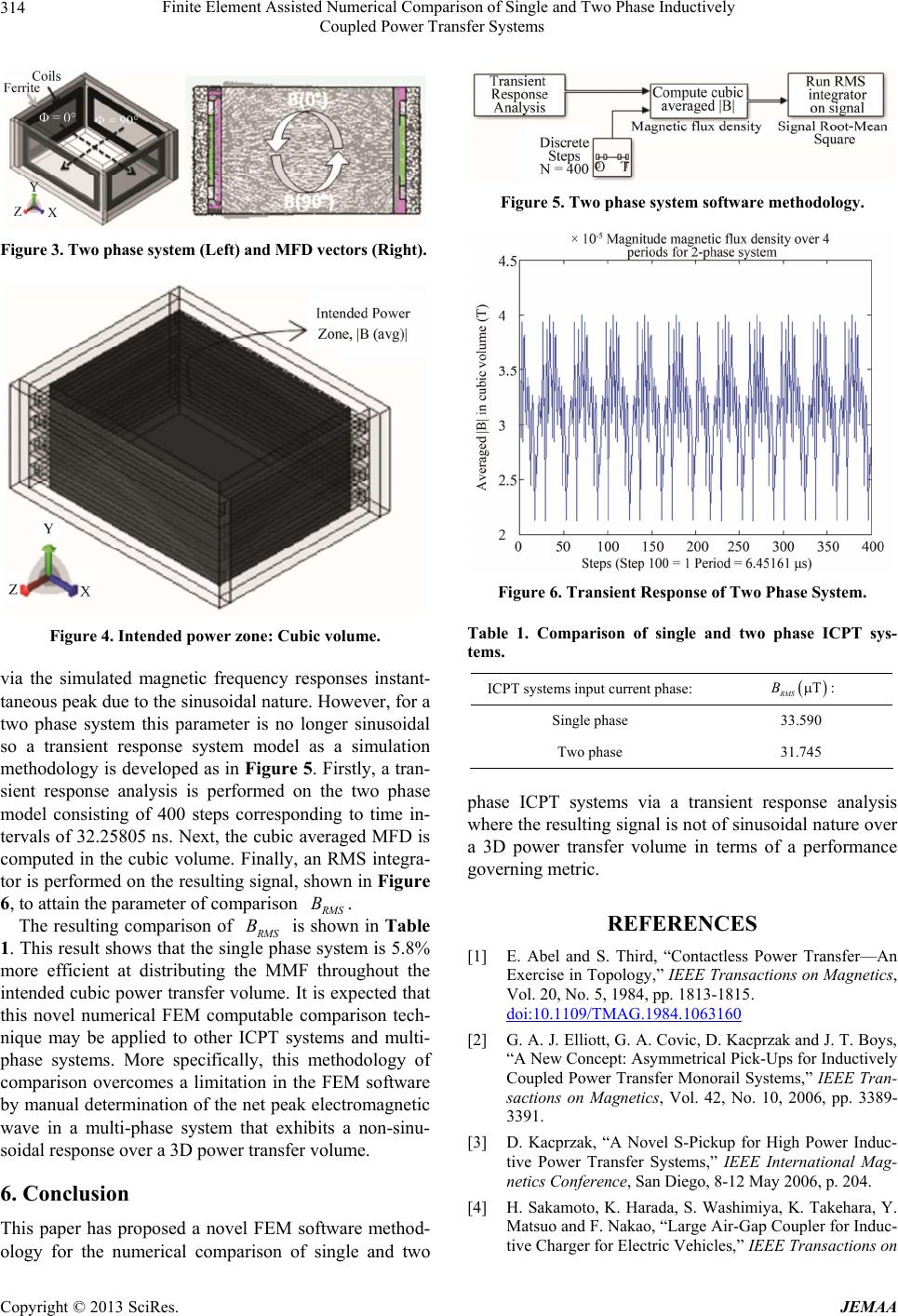 Finite Element Assisted Numerical Comparison of Single and Two Phase Inductively Coupled Power Transfer Systems 314 Figure 3. Two phase system (Left) and MFD vectors (Right). Figure 4. Intended powe r zone : Cubic volume. via the simulated magnetic frequency responses instant- taneous peak due to the sinusoidal nature. However, for a two phase system this parameter is no longer sinusoidal so a transient response system model as a simulation methodology is developed as in Figure 5. Firstly, a tran- sient response analysis is performed on the two phase model consisting of 400 steps corresponding to time in- tervals of 32.25805 ns. Next, the cubic averaged MFD is computed in the cubic volume. Finally, an RMS integra- tor is performed on the resulting signal, shown in Figure 6, to attain the parameter of comparison R MS The resulting comparison of B. R MS is shown in Table 1. This result shows that the single phase system is 5.8% more efficient at distributing the MMF throughout the intended cubic power transfer volume. It is expected that this novel numerical FEM computable comparison tech- nique may be applied to other ICPT systems and multi- phase systems. More specifically, this methodology of comparison overcomes a limitation in the FEM software by manual determination of the net peak electromagnetic wave in a multi-phase system that exhibits a non-sinu- soidal response over a 3D power transfer volume. B 6. Conclusion This paper has proposed a novel FEM software method- ology for the numerical comparison of single and two Figure 5. Two phase system software methodology. Figure 6. Transient Response of Two Phase System. Table 1. Comparison of single and two phase ICPT sys- tems. ICPT systems input current phase: T RMS B: Single phase 33.590 Two phase 31.745 phase ICPT systems via a transient response analysis where the resulting signal is not of sinusoidal nature over a 3D power transfer volume in terms of a performance governing metric. REFERENCES [1] E. Abel and S. Third, “Contactless Power Transfer—An Exercise in Topology,” IEEE Transactions on Magnetics, Vol. 20, No. 5, 1984, pp. 1813-1815. doi:10.1109/TMAG.1984.1063160 [2] G. A. J. Elliott, G. A. Covic, D. Kacprzak and J. T. Boys, “A New Concept: Asymmetrical Pick-Ups for Inductively Coupled Power Transfer Monorail Systems,” IEEE Tran- sactions on Magnetics, Vol. 42, No. 10, 2006, pp. 3389- 3391. [3] D. Kacprzak, “A Novel S-Pickup for High Power Induc- tive Power Transfer Systems,” IEEE International Mag- netics Conference, San Diego, 8-12 May 2006, p. 204. [4] H. Sakamoto, K. Harada, S. Washimiya, K. Takehara, Y. Matsuo and F. Nakao, “Large Air-Gap Coupler for Induc- tive Charge r for El ectric Vehi cles,” IEEE Transactions on Copyright © 2013 SciRes. JEMAA  Finite Element Assisted Numerical Comparison of Single and Two Phase Inductively Coupled Power Transfer Systems Copyright © 2013 SciRes. JEMAA 315 Magnetics, Vol. 35, No. 5, 1999, pp. 3526-3528. doi:10.1109/20.800578 [5] J. M. Barnard, J. A. Fe rreira and J. D. van Wyk, “Sliding Transformer for Linear Contactless Power Delivery,” IEEE Transactions on Magnetics, Vol. 44, No. 6, 1997, pp. 774-779. [6] D. Kacprzak, M. J. Gustafsson and M. P. Taylor, “A Fi- nite Element Method Approach to the Design Process of an Aluminum Reduction Cell,” IEEE International Mag- netics Conference, IEEE Transactions on Magnetics, San Diego, 8-12 May 2006, p. 668. [7] O. H. Stielau and G. A. Covic, “Design of Loosely Cou- pled Inductive Power Transfer Systems,” Proceedings of International Conference on Power Systems Technology, Perth, 4-7 December 2000, pp. 85-90. |