

Paper Menu >>
Journal Menu >>
 Energy and Power Engineering, 2013, 5, 343-351 http://dx.doi.org/10.4236/epe.2013.55035 Published Online July 2013 (http://www.scirp.org/journal/epe) Fuel Saving and Control for Hybrid Electric Powertrains Mohamed Zaher, Sabri Cetinkunt Mechanical and Industrial Engineering Department, University of Illinois at Chicago, Chicago, USA Email: [email protected], [email protected] Received May 7, 2013; revised June 8, 2013; accepted June 15, 2013 Copyright © 2013 Mohamed Zaher, Sabri Cetinkunt. This is an open access article distributed under the Creative Commons Attribu- tion License, which permits unrestricted use, distribution, and reproduction in any medium, provided the original work is properly cited. ABSTRACT This paper focuses on comparing the performance of the embedded control of a hybrid powertrain with the original and downsized engine. The main idea is to store the normally wasted mechanical regenerative energy in energy storage de- vices for later usage. The regenerative energy recovery opportunity exists in any condition where the speed of motion is in the opposite direction to the applied force or torque. A rule based optimal robust control algorithm is developed and is tuned for different work cycles. A comparison of the fuel savings using the hybrid system with the original and downsized engines is performed. Keywords: Hybrid Powertrain; Embedded Control; State of Charge; Downsized Engine 1. Introduction Fuel efficiency and reduced emissions are two of the top considerations in all organic fuel power generations, in- cluding diesel engines [1]. Alternative powertrain con- cepts including hybrid and fuel cell are developed to ful- fill these considerations. The concept behind the hybrid devices is to store the excess, potentially wasted, me- chanical energy in energy storage devices and reuse that energy to support future operations. In any condition where the speed of motion is in opposite direction to the applied force or torque, the regenerative energy recovery opportunity exists (Figure 1 [2]). This condition is satis- fied in various conditions such as (Figure 2): 1) vehicle braking, (i.e., slow down to a lower speed on zero slope or vehicle is moving down a hill and brak- ing must be applied to maintain a desired speed); 2) load is moved by gravitational (load) force. The real time control challenge is to balance the ma- chine power demands from both the engine and the hy- brid storage device. The constraints faced in developing the control strategy are: 1) minimize fuel consumption while meeting low emis- sion requirements; 2) maintain or improve the work-machine productivity; 3) prevent the depletion of the energy storage device, and maintain an acceptable state of charge (SOC). Yafu, and Cheng [3] studied mild hybrid electric vehi- cles (HEV) with integrated starter generator (ISG). By using a parallel assist control strategy and modeling the system in Simulink, they achieved their objective of re- ducing the fuel consumption. Teratani et al. [4] installed a new Toyota hybrid system (THS) which improved fuel economy with 40%. The old THS had slow response, high vibration, and noise during starting and stopping. They managed to reduce the size of the THS. Also, they presented the control logic currently used in most ISG systems, as well as presented a sequence of steps through which the vibration and noise can be minimized. Karden et al. [5] studied the energy storage devices for HEVs and concluded that for the foreseeable future the Lith- ium-ion batteries and Nickel metal hydride will dominate the electric hybrid market for their improved perform- ance and smaller size compared to other storage devices. He and Hodgson [6,7] modeled and simulated the electric hybrid vehicle built by the University of Tennes- see. Their research proposed using a Lithium-ion battery as a modification from the original energy storage device and proposed a control strategy based on the study of the battery state of charge, power output of the engine and the hybrid, and the acceleration capability of the vehicle. Liu and Peng [8] studied the control of Toyota PSHEV using two control algorithms: Stochastic dynamic pro- gramming and equivalent consumptions minimization strategies (ECMS) [9]. They used deterministic dynamic programming solutions as a benchmark for comparisons rather than implementable solutions to assess the per- formance of both algorithms. They concluded that with stochastic dynamic programming (SDP) an extra input operating gear mode is needed beside the engine speed C opyright © 2013 SciRes. EPE 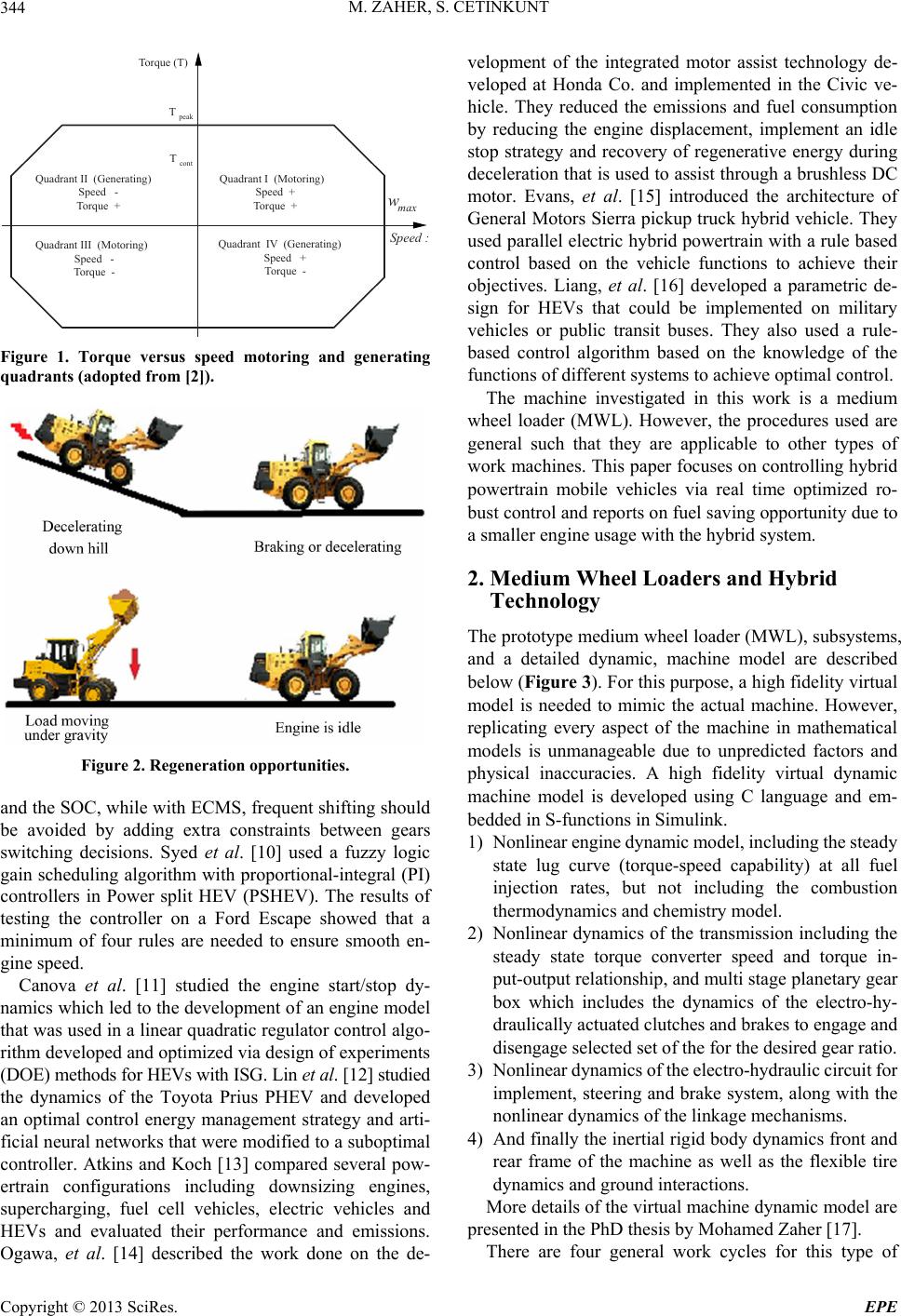 M. ZAHER, S. CETINKUNT 344 Quadrant I (Motoring) Speed + Torque + Quadrant II (Generating) Speed - Torque + Quadrant III (Motoring) Speed - Torque - Quadrant IV (Generating) Speed + Torque - Torque (T) w max Speed : T peak T cont Figure 1. Torque versus speed motoring and generating quadrants (adopted from [2]). Figure 2. Regeneration opportunities. and the SOC, while with ECMS, frequent shifting should be avoided by adding extra constraints between gears switching decisions. Syed et al. [10] used a fuzzy logic gain scheduling algorithm with proportional-integral (PI) controllers in Power split HEV (PSHEV). The results of testing the controller on a Ford Escape showed that a minimum of four rules are needed to ensure smooth en- gine speed. Canova et al. [11] studied the engine start/stop dy- namics which led to the development of an engine model that was used in a linear quadratic regulator control algo- rithm developed and optimized via design of experiments (DOE) methods for HEVs with ISG. Lin et al. [12] studied the dynamics of the Toyota Prius PHEV and developed an optimal control energy management strategy and arti- ficial neural networks that were modified to a suboptimal controller. Atkins and Koch [13] compared several pow- ertrain configurations including downsizing engines, supercharging, fuel cell vehicles, electric vehicles and HEVs and evaluated their performance and emissions. Ogawa, et al. [14] described the work done on the de- velopment of the integrated motor assist technology de- veloped at Honda Co. and implemented in the Civic ve- hicle. They reduced the emissions and fuel consumption by reducing the engine displacement, implement an idle stop strategy and recovery of regenerative energy during deceleration that is used to assist through a brushless DC motor. Evans, et al. [15] introduced the architecture of General Motors Sierra pickup truck hybrid vehicle. They used parallel electric hybrid powertrain with a rule based control based on the vehicle functions to achieve their objectives. Liang, et al. [16] developed a parametric de- sign for HEVs that could be implemented on military vehicles or public transit buses. They also used a rule- based control algorithm based on the knowledge of the functions of different systems to achieve optimal control. The machine investigated in this work is a medium wheel loader (MWL). However, the procedures used are general such that they are applicable to other types of work machines. This paper focuses on controlling hybrid powertrain mobile vehicles via real time optimized ro- bust control and reports on fuel saving opportunity due to a smaller engine usage with the hybrid system. 2. Medium Wheel Loaders and Hybrid Technology The prototype medium wheel loader (MWL), subsystems, and a detailed dynamic, machine model are described below (Figure 3). For this purpose, a high fidelity virtual model is needed to mimic the actual machine. However, replicating every aspect of the machine in mathematical models is unmanageable due to unpredicted factors and physical inaccuracies. A high fidelity virtual dynamic machine model is developed using C language and em- bedded in S-functions in Simulink. 1) Nonlinear engine dynamic model, including the steady state lug curve (torque-speed capability) at all fuel injection rates, but not including the combustion thermodynamics and chemistry model. 2) Nonlinear dynamics of the transmission including the steady state torque converter speed and torque in- put-output relationship, and multi stage planetary gear box which includes the dynamics of the electro-hy- draulically actuated clutches and brakes to engage and disengage selected set of the for the desired gear ratio. 3) Nonlinear dynamics of the electro-hydraulic circuit for implement, steering and brake system, along with the nonlinear dynamics of the linkage mechanisms. 4) And finally the inertial rigid body dynamics front and rear frame of the machine as well as the flexible tire dynamics and ground interactions. More details of the virtual machine dynamic model are presented in the PhD thesis by Mohamed Zaher [17]. There are four general work cycles for this type of Copyright © 2013 SciRes. EPE 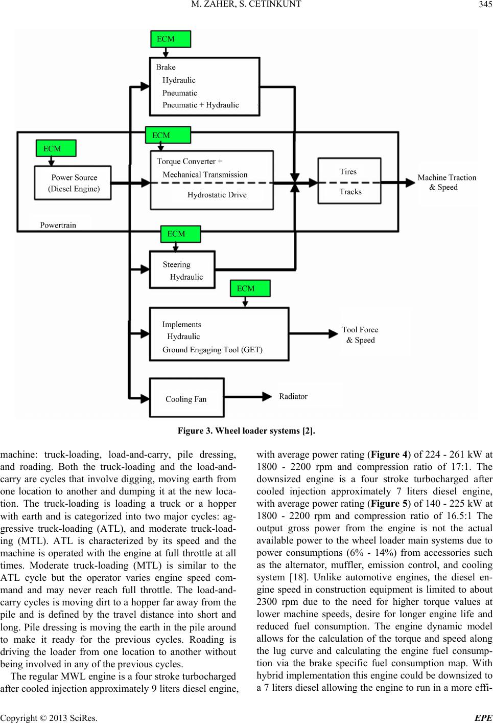 M. ZAHER, S. CETINKUNT Copyright © 2013 SciRes. EPE 345 Figure 3. Wheel loader systems [2]. machine: truck-loading, load-and-carry, pile dressing, and roading. Both the truck-loading and the load-and- carry are cycles that involve digging, moving earth from one location to another and dumping it at the new loca- tion. The truck-loading is loading a truck or a hopper with earth and is categorized into two major cycles: ag- gressive truck-loading (ATL), and moderate truck-load- ing (MTL). ATL is characterized by its speed and the machine is operated with the engine at full throttle at all times. Moderate truck-loading (MTL) is similar to the ATL cycle but the operator varies engine speed com- mand and may never reach full throttle. The load-and- carry cycles is moving dirt to a hopper far away from the pile and is defined by the travel distance into short and long. Pile dressing is moving the earth in the pile around to make it ready for the previous cycles. Roading is driving the loader from one location to another without being involved in any of the previous cycles. The regular MWL engine is a four stroke turbocharged after cooled injection approximately 9 liters diesel engine, with average power rating (Figure 4) of 224 - 261 kW at 1800 - 2200 rpm and compression ratio of 17:1. The downsized engine is a four stroke turbocharged after cooled injection approximately 7 liters diesel engine, with average power rating (Figure 5) of 140 - 225 kW at 1800 - 2200 rpm and compression ratio of 16.5:1 The output gross power from the engine is not the actual available power to the wheel loader main systems due to power consumptions (6% - 14%) from accessories such as the alternator, muffler, emission control, and cooling system [18]. Unlike automotive engines, the diesel en- gine speed in construction equipment is limited to about 2300 rpm due to the need for higher torque values at lower machine speeds, desire for longer engine life and reduced fuel consumption. The engine dynamic model allows for the calculation of the torque and speed along the lug curve and calculating the engine fuel consump- tion via the brake specific fuel consumption map. With hybrid implementation this engine could be downsized to a 7 liters diesel allowing the engine to run in a more effi- 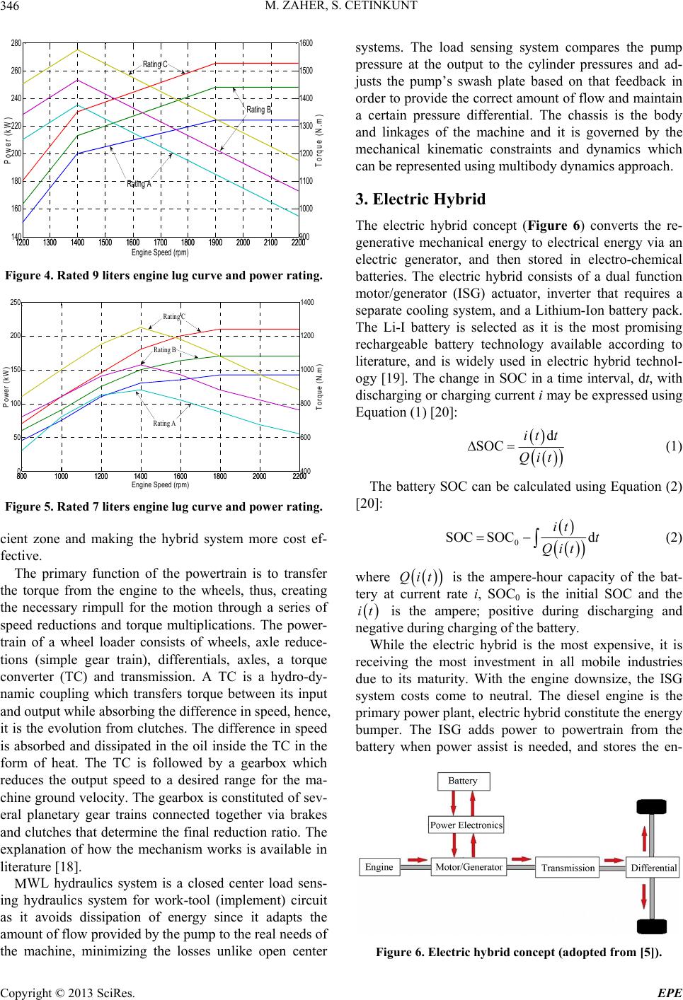 M. ZAHER, S. CETINKUNT 346 12001300 1400 1500 1600 17001800 1900 2000 2100 2200 140 160 180 200 220 240 260 280 P ow e r (kW) Engine Speed (rpm) 12001300 1400 1500 1600 17001800 1900 2000 1600 1500 1400 1300 1200 1100 2100 2200 900 1000 Torque (N.m ) Rating A Rating B Rating C Figure 4. Rated 9 liters engine lug curve and power rating. 8001000 1200 1400 1600 1800 20002200 0 50 100 150 200 250 P ow e r (kW) En gine Speed (rpm) 8001000 1200 1400 1600 1800 20002200 400 600 800 1000 1200 1400 T orque (N.m ) Rating A Rating B Rating C Figure 5. Rated 7 liters engine lug curve and power rating. cient zone and making the hybrid system more cost ef- fective. The primary function of the powertrain is to transfer the torque from the engine to the wheels, thus, creating the necessary rimpull for the motion through a series of speed reductions and torque multiplications. The power- train of a wheel loader consists of wheels, axle reduce- tions (simple gear train), differentials, axles, a torque converter (TC) and transmission. A TC is a hydro-dy- namic coupling which transfers torque between its input and output while absorbing the difference in speed, hence, it is the evolution from clutches. The difference in speed is absorbed and dissipated in the oil inside the TC in the form of heat. The TC is followed by a gearbox which reduces the output speed to a desired range for the ma- chine ground velocity. The gearbox is constituted of sev- eral planetary gear trains connected together via brakes and clutches that determine the final reduction ratio. The explanation of how the mechanism works is available in literature [18]. MWL hydraulics system is a closed center load sens- ing hydraulics system for work-tool (implement) circuit as it avoids dissipation of energy since it adapts the amount of flow provided by the pump to the real needs of the machine, minimizing the losses unlike open center systems. The load sensing system compares the pump pressure at the output to the cylinder pressures and ad- justs the pump’s swash plate based on that feedback in order to provide the correct amount of flow and maintain a certain pressure differential. The chassis is the body and linkages of the machine and it is governed by the mechanical kinematic constraints and dynamics which can be represented using multibody dynamics approach. 3. Electric Hybrid The electric hybrid concept (Figure 6) converts the re- generative mechanical energy to electrical energy via an electric generator, and then stored in electro-chemical batteries. The electric hybrid consists of a dual function motor/generator (ISG) actuator, inverter that requires a separate cooling system, and a Lithium-Ion battery pack. The Li-I battery is selected as it is the most promising rechargeable battery technology available according to literature, and is widely used in electric hybrid technol- ogy [19]. The change in SOC in a time interval, dt, with discharging or charging current i may be expressed using Equation (1) [20]: d SOC it t Qit (1) The battery SOC can be calculated using Equation (2) [20]: 0 SOC SOCd it t Qit (2) where Qit is the ampere-hour capacity of the bat- tery at current rate i, SOC0 is the initial SOC and the it is the ampere; positive during discharging and negative during charging of the battery. While the electric hybrid is the most expensive, it is receiving the most investment in all mobile industries due to its maturity. With the engine downsize, the ISG system costs come to neutral. The diesel engine is the primary power plant, electric hybrid constitute the energy bumper. The ISG adds power to powertrain from the battery when power assist is needed, and stores the en- Figure 6. Electric hybrid concept (adopted from [5]). Copyright © 2013 SciRes. EPE 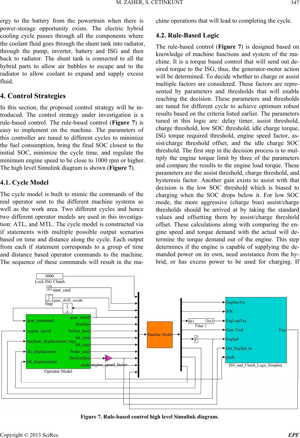 M. ZAHER, S. CETINKUNT Copyright © 2013 SciRes. EPE 347 ergy to the battery from the powertrain when there is power-storage opportunity exists. The electric hybrid cooling cycle passes through all the components where the coolant fluid goes through the shunt tank into radiator, through the pump, inverter, battery and ISG and then back to radiator. The shunt tank is connected to all the hybrid parts to allow air bubbles to escape and to the radiator to allow coolant to expand and supply excess fluid. chine operations that will lead to completing the cycle. 4.2. Rule-Based Logic The rule-based control (Figure 7) is designed based on knowledge of machine functions and system of the ma- chine. It is a torque based control that will send out de- sired torque to the ISG, thus, the generator-motor action will be determined. To decide whether to charge or assist multiple factors are considered. These factors are repre- sented by parameters and thresholds that will enable reaching the decision. These parameters and thresholds are tuned for different cycle to achieve optimum robust results based on the criteria listed earlier. The parameters tuned in this logic are: delay timer, assist threshold, charge threshold, low SOC threshold, idle charge torque, ISG torque required threshold, engine speed factor, as- sist/charge threshold offset, and the idle charge SOC threshold. The first step in the decision process is to mul- tiply the engine torque limit by three of the parameters and compare the results to the engine load torque. These parameters are the assist threshold, charge threshold, and hysteresis factor. Another gain exists to assist with that decision is the low SOC threshold which is biased to charging when the SOC drops below it. For low SOC mode, the more aggressive (charge bias) assist/charge thresholds should be arrived at by taking the standard values and offsetting them by assist/charge threshold offset. These calculations along with comparing the en- gine speed and torque demand with the actual will de- termine the torque demand out of the engine. This step determines if the engine is capable of supplying the de- manded power on its own, need assistance from the hy- brid, or has excess power to be used for charging. If 4. Control Strategies In this section, the proposed control strategy will be in- troduced. The control strategy under investigation is a rule-based control. The rule-based control (Figure 7) is easy to implement on the machine. The parameters of this controller are tuned to different cycles to minimize the fuel consumption, bring the final SOC closest to the initial SOC, minimize the cycle time, and regulate the minimum engine speed to be close to 1000 rpm or higher. The high level Simulink diagram is shown (Figure 7). 4.1. Cycle Model The cycle model is built to mimic the commands of the real operator sent to the different machine systems as well as the work area. Two different cycles and hence two different operator models are used in this investiga- tion: ATL, and MTL. The cycle model is constructed via if statements with multiple possible output scenarios based on time and distance along the cycle. Each output from each if statement corresponds to a group of time and distance based operator commands to the machine. The sequence of these commands will result in the ma- Figure 7. Rule-based control high level Simulink diagram. 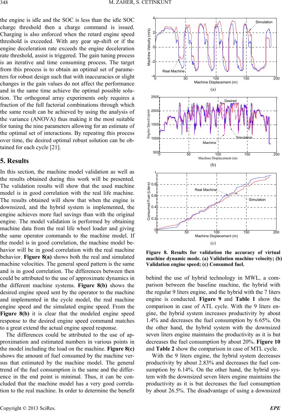 M. ZAHER, S. CETINKUNT 348 4 the engine is idle and the SOC is less than the idle SOC charge threshold then a charge command is issued. Charging is also enforced when the retard engine speed threshold is exceeded. With any gear up-shift or if the engine deceleration rate exceeds the engine deceleration rate threshold, assist is triggered. The gain tuning process is an iterative and time consuming process. The target from this process is to obtain an optimal set of parame- ters for robust design such that with inaccuracies or slight changes in the gain values do not affect the performance and in the same time achieve the optimal possible solu- tion. The orthogonal array experiments only requires a fraction of the full factorial combinations through which the same result can be achieved by using the analysis of the variance (ANOVA) thus making it the most suitable for tuning the nine parameters allowing for an estimate of the optimal set of interactions. By repeating this process over time, the desired optimal robust solution can be ob- tained for each cycle [21]. 5. Results In this section, the machine model validation as well as the results obtained during this work will be presented. The validation results will show that the used machine model is in good correlation with the real life machine. The results obtained will show that when the engine is downsized, and the hybrid system is implemented, the engine achieves more fuel savings than with the original engine. The model validation is performed by obtaining machine data from the real life wheel loader and giving the same operator commands to the machine model. If the model is in good correlation, the machine model be- havior will be in good correlation with the real machine behavior. Figure 8(a) shows both the real and simulated machine velocities. The general speed pattern is the same and is in good correlation. The differences between then could be attributed to the use of approximate dynamics in the different machine systems. Figure 8(b) shows the desired engine speed sent by the operator to the machine and implemented in the cycle model, the real machine engine speed and the simulated engine speed. From the Figure 8(b) it is clear that the modeled engine speed response to the desired engine speed command matches to a great extend the actual engine speed response. The differences could be attributed to the use of ap- proximation and estimated numbers in various points in the model including the load on the machine. Figure 8(c) shows the amount of fuel consumed by the machine ver- sus that estimated by the machine model. The general trend of the fuel consumption is the same and the differ- ence in the end point is minimal. Thus, it can be con- cluded that the machine model has a very good correla- tion to the real machine. In order to determine the benefit 050100 150 200 -4 -2 0 2 Simulation Machine Displacement (m) Machine Velocity (m/s) Real Machine (a) 2500 050100 150 200 500 1000 1500 2000 Desired Engine Speed (rpm) Simulation Machine Machine Dis p lacement ( m ) (b) 1 0.8 050 100 150 200 0 0.2 0.4 0.6 Machine Displacement (m ) Consumed Fuel (Liters) Real Machine Simu lation (c) Figure 8. Results for validation the accuracy of virtual machine dynamic mode. (a) Validation machine velocity; (b) Validation engine speed; (c) Consumed fuel. behind the use of hybrid technology in MWL, a com- parison between the baseline machine, the hybrid with the regular 9 liters engine, and the hybrid with the 7 liters engine is conducted. Figure 9 and Table 1 show the comparison in case of ATL cycle. With the 9 liters en- gine, the hybrid system increases productivity by about 1.4% and decreases the fuel consumption by 6.65%. On the other hand, the hybrid system with the downsized seven liters engine maintains the productivity as it is but decreases the fuel consumption by about 20%. Figure 10 and Table 2 show the comparison in case of MTL cycle. With the 9 liters engine, the hybrid system decreases productivity by about 2.83% and decreases the fuel con- sumption by 6.14%. On the other hand, the hybrid sys- tem with the downsized seven liters engine maintains the productivity as it is but decreases the fuel consumption y about 26.5%. The disadvantage of using a downsized b Copyright © 2013 SciRes. EPE 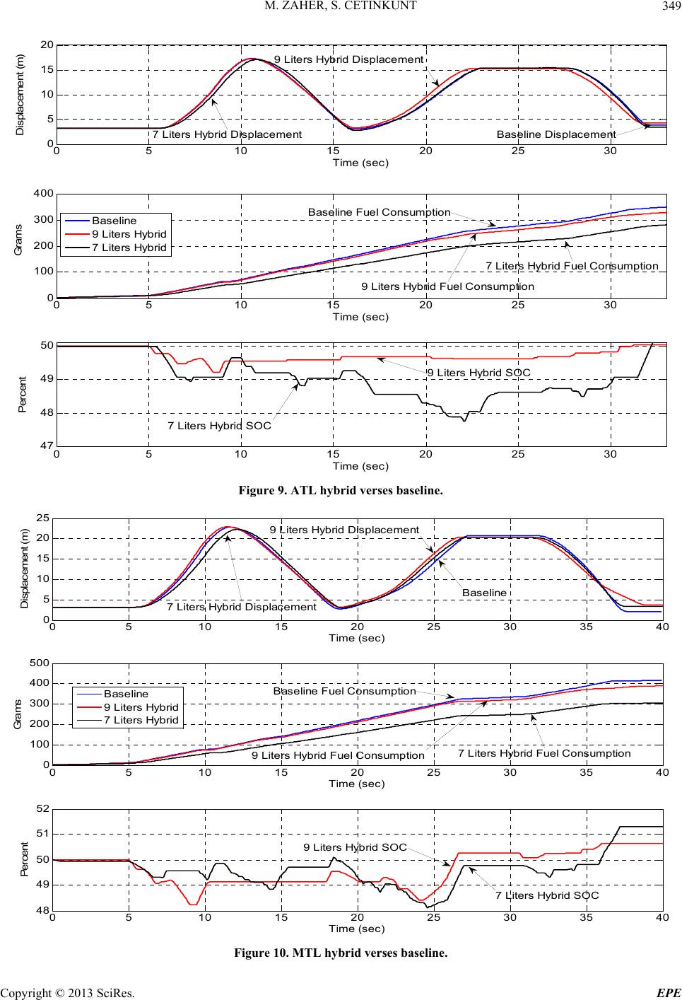 M. ZAHER, S. CETINKUNT 349 05 10 1520 25 30 0 5 10 15 20 Tim e (sec) Disp lacem en t (m ) 05 10 1520 25 30 0 100 200 300 400 Tim e (sec) Grams 05 10 1520 25 30 47 48 49 50 Tim e (sec) Percent Bas eline 9 Li ters Hybrid 7 Li ters Hybrid Baseline Displacement 9 Li ters Hybrid Displacem ent Baseline Fuel Consumption 9 Li ters Hybri d Fuel C ons umption 7 Li ters Hybrid SO C 9 Li ters Hybri d SO C 7 Liters Hybrid Fuel Cons umption 7 Li ters Hybri d D isplacem ent Figure 9. ATL hybrid verses baseline. 05 10 15 20 25 30 35 40 0 5 10 15 20 25 Tim e (sec) D isplacem en t (m ) 05 10 15 20 25 30 35 40 0 100 200 300 400 500 Tim e (sec) Grams 05 10 15 20 25 30 35 40 48 49 50 51 52 Tim e (sec) Percent Base line 9 Liter s Hybrid 7 Liter s Hybrid 9 Li ters Hybrid S OC Baseline Fuel Consumption 9 Liters Hybrid Fuel Cons um ption7 Liters Hybrid Fu el Cons um p ti o n 7 Li ters Hyb rid S OC Base line 7 Li ters Hybrid Displ ac em ent 9 Li ters Hybrid D ispl ac em ent Figure 10. MTL hybrid verses baseline. Copyright © 2013 SciRes. EPE 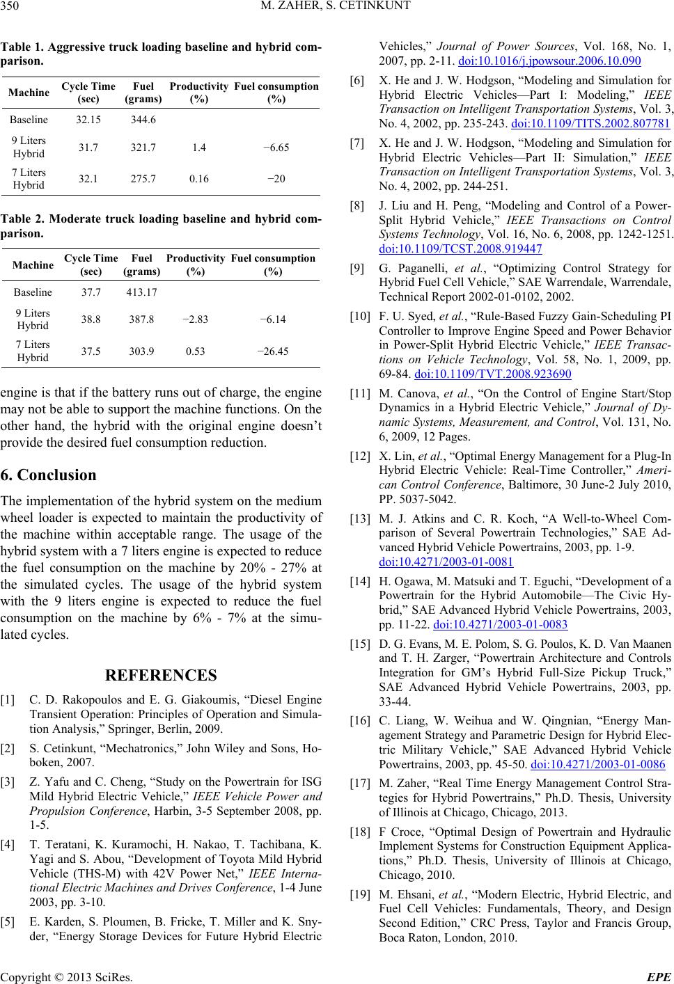 M. ZAHER, S. CETINKUNT 350 Table 1. Aggressive truck loading baseline and hybrid com- parison. Machine Cycle Time (sec) Fuel (grams) Productivity (%) Fuel consumption (%) Baseline 32.15 344.6 9 Liters Hybrid 31.7 321.7 1.4 −6.65 7 Liters Hybrid 32.1 275.7 0.16 −20 Table 2. Moderate truck loading baseline and hybrid com- parison. Machine Cycle Time (sec) Fuel (grams) Productivity (%) Fuel c onsumption (%) Baseline 37.7 413.17 9 Liters Hybrid 38.8 387.8 −2.83 −6.14 7 Liters Hybrid 37.5 303.9 0.53 −26.45 engine is that if the battery runs out of charge, the engine may not be able to support the machine functions. On the other hand, the hybrid with the original engine doesn’t provide the desired fuel consumption reduction. 6. Conclusion The implementation of the hybrid system on the medium wheel loader is expected to maintain the productivity of the machine within acceptable range. The usage of the hybrid system with a 7 liters engine is expected to reduce the fuel consumption on the machine by 20% - 27% at the simulated cycles. The usage of the hybrid system with the 9 liters engine is expected to reduce the fuel consumption on the machine by 6% - 7% at the simu- lated cycles. REFERENCES [1] C. D. Rakopoulos and E. G. Giakoumis, “Diesel Engine Transient Operation: Principles of Operation and Simula- tion Analysis,” Springer, Berlin, 2009. [2] S. Cetinkunt, “Mechatronics,” John Wiley and Sons, Ho- boken, 2007. [3] Z. Yafu and C. Cheng, “Study on the Powertrain for ISG Mild Hybrid Electric Vehicle,” IEEE Vehicle Power and Propulsion Conference, Harbin, 3-5 September 2008, pp. 1-5. [4] T. Teratani, K. Kuramochi, H. Nakao, T. Tachibana, K. Yagi and S. Abou, “Development of Toyota Mild Hybrid Vehicle (THS-M) with 42V Power Net,” IEEE Interna- tional Electric Machines and Drives Conference, 1-4 June 2003, pp. 3-10. [5] E. Karden, S. Ploumen, B. Fricke, T. Miller and K. Sny- der, “Energy Storage Devices for Future Hybrid Electric Vehicles,” Journal of Power Sources, Vol. 168, No. 1, 2007, pp. 2-11. doi:10.1016/j.jpowsour.2006.10.090 [6] X. He and J. W. Hodgson, “Modeling and Simulation for Hybrid Electric Vehicles—Part I: Modeling,” IEEE Transaction on Intelligent Transportation Systems, Vol. 3, No. 4, 2002, pp. 235-243. doi:10.1109/TITS.2002.807781 [7] X. He and J. W. Hodgson, “Modeling and Simulation for Hybrid Electric Vehicles—Part II: Simulation,” IEEE Transaction on Intelligent Transportation Systems, Vol. 3, No. 4, 2002, pp. 244-251. [8] J. Liu and H. Peng, “Modeling and Control of a Power- Split Hybrid Vehicle,” IEEE Transactions on Control Systems Technology, Vol. 16, No. 6, 2008, pp. 1242-1251. doi:10.1109/TCST.2008.919447 [9] G. Paganelli, et al., “Optimizing Control Strategy for Hybrid Fuel Cell Vehicle,” SAE Warrendale, Warrendale, Technical Report 2002-01-0102, 2002. [10] F. U. Syed, et al., “Rule-Based Fuzzy Gain-Scheduling PI Controller to Improve Engine Speed and Power Behavior in Power-Split Hybrid Electric Vehicle,” IEEE Transac- tions on Vehicle Technology, Vol. 58, No. 1, 2009, pp. 69-84. doi:10.1109/TVT.2008.923690 [11] M. Canova, et al., “On the Control of Engine Start/Stop Dynamics in a Hybrid Electric Vehicle,” Journal of Dy- namic Systems, Measurement, and Control, Vol. 131, No. 6, 2009, 12 Pages. [12] X. Lin, et al., “Optimal Energy Management for a Plug-In Hybrid Electric Vehicle: Real-Time Controller,” Ameri- can Control Conference, Baltimore, 30 June-2 July 2010, PP. 5037-5042. [13] M. J. Atkins and C. R. Koch, “A Well-to-Wheel Com- parison of Several Powertrain Technologies,” SAE Ad- vanced Hybrid Vehicle Powertrains, 2003, pp. 1-9. doi:10.4271/2003-01-0081 [14] H. Ogawa, M. Matsuki and T. Eguchi, “Development of a Powertrain for the Hybrid Automobile—The Civic Hy- brid,” SAE Advanced Hybrid Vehicle Powertrains, 2003, pp. 11-22. doi:10.4271/2003-01-0083 [15] D. G. Evans, M. E. Polom, S. G. Poulos, K. D. Van Maanen and T. H. Zarger, “Powertrain Architecture and Controls Integration for GM’s Hybrid Full-Size Pickup Truck,” SAE Advanced Hybrid Vehicle Powertrains, 2003, pp. 33-44. [16] C. Liang, W. Weihua and W. Qingnian, “Energy Man- agement Strategy and Parametric Design for Hybrid Elec- tric Military Vehicle,” SAE Advanced Hybrid Vehicle Powertrains, 2003, pp. 45-50. doi:10.4271/2003-01-0086 [17] M. Zaher, “Real Time Energy Management Control Stra- tegies for Hybrid Powertrains,” Ph.D. Thesis, University of Illinois at Chicago, Chicago, 2013. [18] F Croce, “Optimal Design of Powertrain and Hydraulic Implement Systems for Construction Equipment Applica- tions,” Ph.D. Thesis, University of Illinois at Chicago, Chicago, 2010. [19] M. Ehsani, et al., “Modern Electric, Hybrid Electric, and Fuel Cell Vehicles: Fundamentals, Theory, and Design Second Edition,” CRC Press, Taylor and Francis Group, Boca Raton, London, 2010. Copyright © 2013 SciRes. EPE  M. ZAHER, S. CETINKUNT 351 [20] M. Ehsani, et al., “Modern Electric, Hybrid Electric, and Fuel Cell Vehicles, Fundamentals, Theory, and Design,” PPCRC Press, Boca Raton, 2010. [21] Y. W. Fowlkes and C. M. Creveling, “Engineering Me- thods for Robust Product Design Using Taguchi Methods in Technology and Product Development,” Prentice Hall, Upper Saddle River, 1995. Copyright © 2013 SciRes. EPE |