

Paper Menu >>
Journal Menu >>
 Circuits and Systems, 2013, 4, 264-268 http://dx.doi.org/10.4236/cs.2013.43035 Published Online July 2013 (http://www.scirp.org/journal/cs) Fully Uncoupled Electronically Controllable Sinusoidal Oscillator Employing VD-DIBAs Data Ram Bhaskar1*, Dinesh Prasad1, Kanhaiya Lal Pushkar2 1Department of Electronics and Communication Engineering, Faculty of Engineering and Technology, Jamia Millia Islamia, New Delhi, India 2Department of Electronics and Communication Engineering, Maharaja Agrasen Institute of Technology, Rohini, New Delhi, India Email: *[email protected], [email protected]c.in, [email protected] Received March 21, 2013; revised April 22, 2013; accepted April 30, 2013 Copyright © 2013 Data Ram Bhaskar et al. This is an open access article distributed under the Creative Commons Attribution Li- cense, which permits unrestricted use, distribution, and reproduction in any medium, provided the original work is properly cited. ABSTRACT Recently, voltage differencing-differential input buffered amplifiers (VD-DIBA)-based electronically controllable si- nusoidal oscillator has been presented that it does not have the capability of complete independence of frequency of oscillation (FO) and condition of oscillation (CO) as well as electronic control of both CO and FO. In this article, a new fully-uncoupled electronically controllable sinusoidal oscillator using two VD-DIBAs, two grounded capacitors and two resistors has been proposed which offers important advantages such as 1) totally uncoupled and electronically con- trolled condition of oscillation (CO) and frequency of oscillation (FO); 2) low active and passive sensitivities; and 3) a very good frequency stability factor. The effects of non-idealities of the VD-DIBAs on the proposed oscillator are also investigated. The validity of the proposed formulation has been confirmed by SPICE simulation with TSMC 0.18 μm process parameters. Keywords: Sinusoidal Oscillator; Voltage-Mode; VD-DIBA 1. Introduction Sinusoidal oscillators find various applications in signal processing, instrumentation, measurement, communica- tion and control systems. The class of single resistance controlled oscillators (SRCOs) using different active element(s)/device(s) has been of particular interest dur- ing the last four decades because of their applications in variable frequency oscillators. However, in these SRCOs, electronic control of CO and FO can be obtained by re- placing the respective controlling resistor(s) with FET based or CMOS voltage controlled resistor(s). A careful inspection of the available SRCOs reveals that while many oscillators enjoy independent single element con- trol of CO and FO, the class of fully uncoupled oscilla- tors has not been considered adequately in the literature. In fully uncoupled oscillator circuits CO and FO are de- termined by two completely different sets of active and/ or passive components, that is none of the active and/or passive components appeared in CO are involved in FO and vice versa. This feature is very useful for realizing voltage controlled oscillators as FO can be controlled independently without disturbing CO, whereas the flexi- bility of being able to control CO independently is ad- vantageous to incorporate amplitude stabilization. In the recent past, number of fully-uncoupled sinusoidal oscil- lators employing different active element(s)/devices has been introduced see [1-7] and the references cited therein. In references [1-5] the CO and FO of the proposed oscil- lators are adjustable through resistors (the electronic tunability can be established by replacing one of the grounded resistors by JFETs/MOSFETs [8,9]), whereas in case of oscillators presented in references [6,7], both CO and FO are electronically controllable. The VD- DIBA was introduced by Biolek, Senani, Biolkova and Kolka in [10] since then it has been found to be a useful new active building block in realizing all voltage-mode pass filters [11], inductance simulation [12], universal biquad filter [13] and an electronically controllable sinu- soidal oscillator [14]. Although the paper presented by the authors in [14] employs two VD-DIBAs, two grounded capacitors and one grounded resistor but this circuit does not have the capability of complete independence of CO and FO as well as electronic control (only FO is elec- tronically controllable). Therefore, the purpose of this *Corresponding author. C opyright © 2013 SciRes. CS 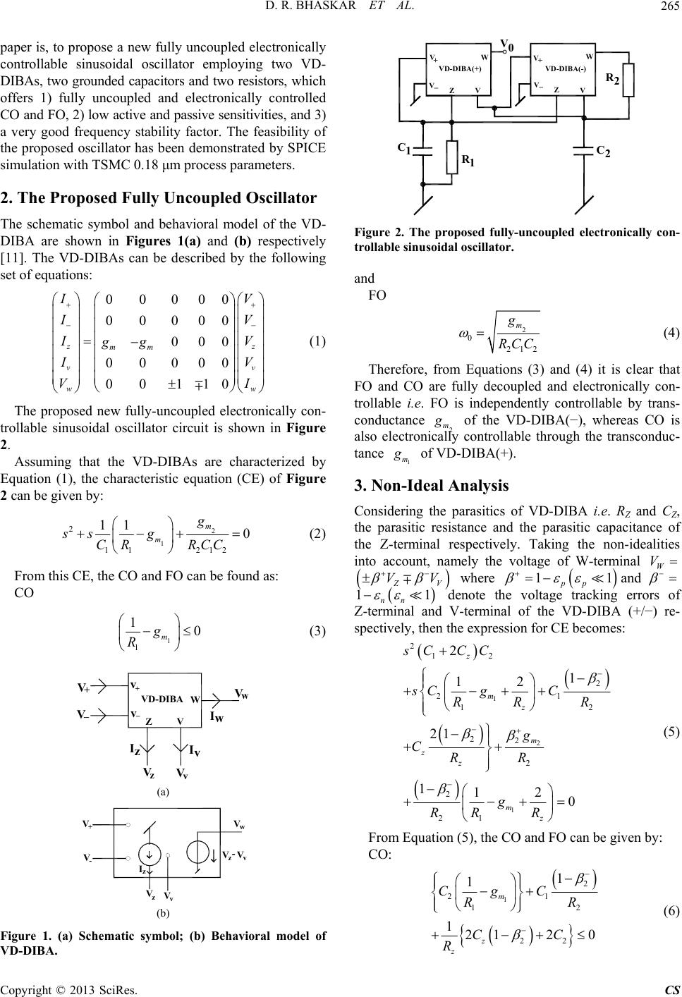 D. R. BHASKAR ET AL. 265 paper is, to propose a new fully uncoupled electronically controllable sinusoidal oscillator employing two VD- DIBAs, two grounded capacitors and two resistors, which offers 1) fully uncoupled and electronically controlled CO and FO, 2) low active and passive sensitivities, and 3) a very good frequency stability factor. The feasibility of the proposed oscillator has been demonstrated by SPICE simulation with TSMC 0.18 μm process parameters. VD-DIBA(+) VD-DIBA(-) V + V_V + V _Z ZV V WW C2 C1R1 R2 2. The Proposed Fully Uncoupled Oscillator The schematic symbol and behavioral model of the VD- DIBA are shown in Figures 1(a) and (b) respectively [11]. The VD-DIBAs can be described by the following set of equations: 000 000 000 00 00 00 000 00 110 z z vv w mm w I V I V I V gg I V I V (1) V0 Figure 2. The proposed fully-uncoupled electronically con- nd The proposed new fully-uncoupled electronically con- trollable sinusoidal oscillator circuit is shown in Figure 2. Assuming that the VD-DIBAs are characterized by Equation (1), the characteristic equation (CE) of Figure 2 can be given by: 2 212 0 m g RCC 1 2 11 11 m ss g CR (2) From this CE, the CO and FO can be found as: CO 1 1 10 m g R (3) V+ V_ Iz v+ v_ Vz Z VD-DIB Iv Iw Vv Vw V W A (a) V+ V- VzVv Vw Vz-Vv Iz (b) Figure 1. (a) Schematic symbol; (b) Behavioral model of trollable sinusoidal oscillator. a FO 2 0 212 m g RCC (4) Therefore, from Equations (3) and (4) it is clear that FO and CO are fully decoupled and electronically con- trollable i.e. FO is independently controllable by trans- conductance 2 m g of the VD-DIBA(−), whereas CO is also electroni controllable through the transconduc- tance 1 m cally g of VD-DIBA(+). 3. Non-Ideal Analysis f VD-DIBA i.e. RZ and CZ, Considering the parasitics o the parasitic resistance and the parasitic capacitance of the Z-terminal respectively. Taking the non-idealities into account, namely the voltage of W-terminal W V Z V VV where 11 pp and 11 nn e voltage trackingrs of Z-terminal and denote th erro V-terminal of the VD-DIBA (+/−) re- spectively, then the expression for CE becomes: VD-DIBA. 1 2 1 12 2 21 12 22 2 2 21 1 12 21 112 0 z mz m zz mz sC g C RR R g CRR g RR R 22sC CC (5) From Equation (5), the CO and FO can be given by: CO: 1 2 21 12 22 1 1 1212 0 m z z CgC RR CC R (6) Copyright © 2013 SciRes. CS 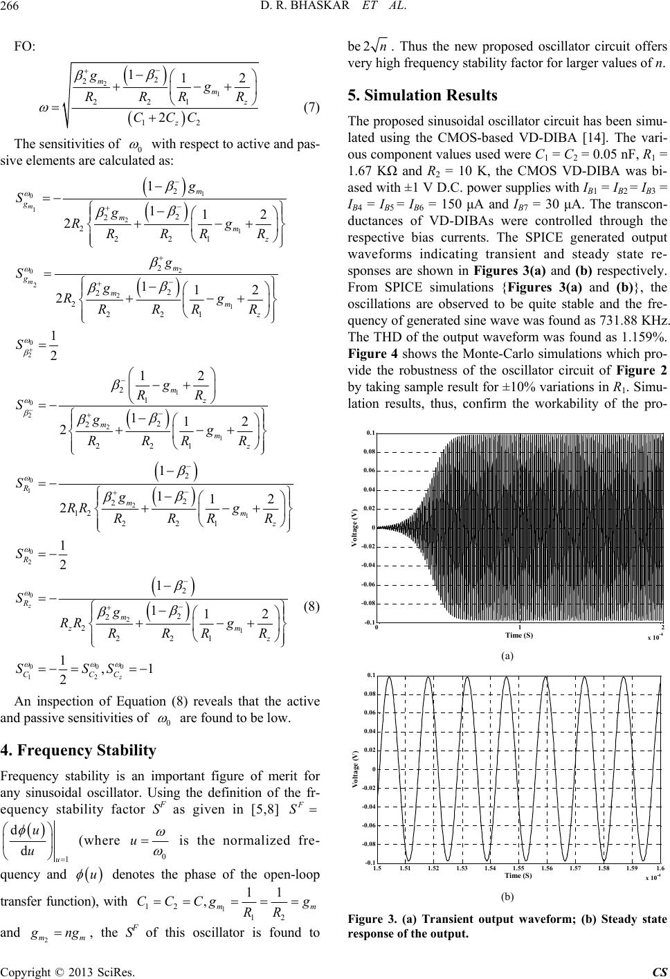 D. R. BHASKAR ET AL. 266 FO: 22 2 22 1 1 1 12 1 2 mmz z gg RRR R CCC (7) ivities of 0 2 The sensit with respect to active and pas- sive elements are calculated as: 1 0 1 2 1 2 22 1 2mz Rg RR R R 2 0 2 2 1 0 2 1 0 2 2 1 2 2 2 2 2 2 2 221 2 1 2 2 221 1 112 112 2 1 2 12 112 2 m m m g m m g mmz mz mmz g Sg g Sg Rg RRR R S g RR Sgg RRRR 0 1 2 1 0 2 0 2 1 000 12 2 2 2 12 221 2 2 2 2 221 1 112 2 1 2 1 112 1,1 2 z z R mmz R R m zm z CCC Sg RR g RRRR S Sg RR g RRR R SSS (8) An inspection of Equation (8) reveals that the a and passive sensitivities of 0 ctive are found to be low. 4. Frequency Stability Frequency stability is an important figure of merit for an F y sinusoidal oscillator. Using the definition of the fr- equency stability factor Sas given in [5,8] F S 1 u d d u u (where 0 u is the normalized fre- quency and u denotes the phase of the open-loop transfer function), with 1 12 11 , m CCCg 12 m g RR 2 mm ng , the SF of this oscillator is found to be 2n. Thus the new proposed oscillator circuit offers very high frequency stability f oscillator circuit has been simu lated using the CMOS-based VD-DIBA [14]. The vari- omponent 7 K IB7 = 30 μA. The transcon- ere controlled through the and actor for larger values of n. 5. Simulation Results The proposed sinusoidal- ous cvalues used were C1 = C2 = 0.05 nF, R1 = 1.6 Ω and R2 = 10 K, the CMOS VD-DIBA was bi- ased with ±1 V D.C. power supplies with IB1 = IB2 = IB3 = IB4 = IB5 = IB6 = 150 μA and ductances of VD-DIBAs w respective bias currents. The SPICE generated output waveforms indicating transient and steady state re- sponses are shown in Figures 3(a) and (b) respectively. From SPICE simulations {Figures 3(a) and (b)}, the oscillations are observed to be quite stable and the fre- quency of generated sine wave was found as 731.88 KHz. The THD of the output waveform was found as 1.159%. Figure 4 shows the Monte-Carlo simulations which pro- vide the robustness of the oscillator circuit of Figure 2 by taking sample result for ±10% variations in R1. Simu- lation results, thus, confirm the workability of the pro- g 012 x 10 -4 -0.1 -0.08 -0.06 -0.04 -0.02 0 0.02 0.04 0.06 0.08 0.1 Voltage (V) Time (S) (a) 0.1 0.08 0.06 0.04 0.02 0 -0.02 -0.04 -0.06 -0.08 1.5 -0.1 1.51 1.521.53 1.54 1.551.56 1.57 1.58 1.591.6 x 10 -4 Time (S) Voltage (V) (b) Figure 3. (a) Transient output waveform; (b) Steady state response of the output. Copyright © 2013 SciRes. CS 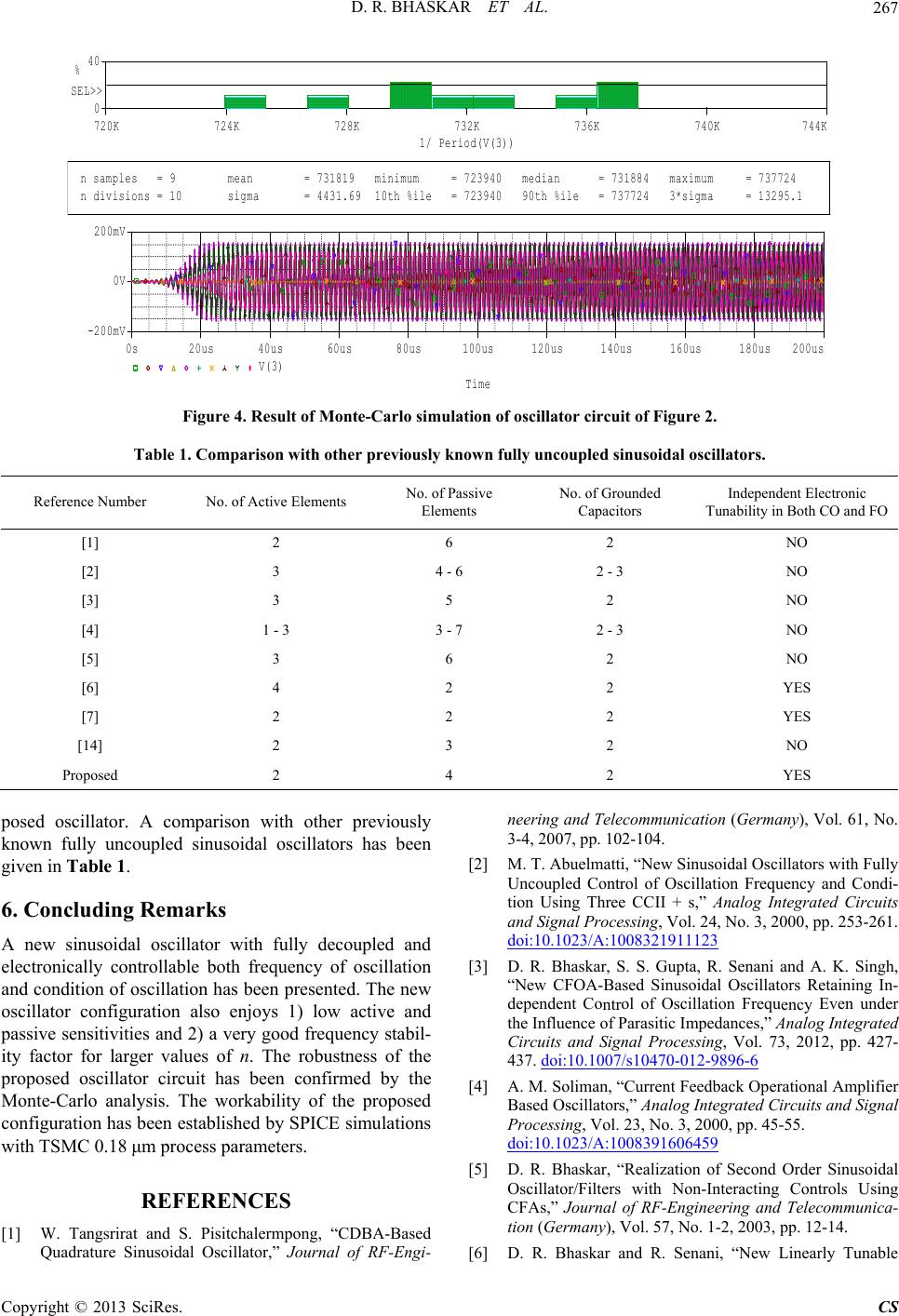 D. R. BHASKAR ET AL. Copyright © 2013 SciRes. CS 267 Time 0s20us40us60us80us100us 120us 140us 160us 180us200us V(3) -200mV 0V 200mV 1/ Period(V(3)) 720K 724K 728K 732K 736K 740K744K 0 40 % SEL>> n samples= 9 n divisions= 10mean= 731819 sigma= 4431.69minimum= 723940 10th %ile= 723940median= 731884 90th %ile= 737724maximum 3*sigma = 737724 = 13295.1 Figure 4. Result of Monte-Carlo simulation of oscillator circuit of Figure 2. Table 1. Comparison with other previously known fully uncoupled sinusoidal osc illators. Reference Number No. of Active Elements No. of Passive Elements No. of Grounded Capacitors Independent Electronic Tunability in Both CO and FO [1] 2 6 2 NO [2] 3 4 - 6 2 - 3 NO [3] 3 5 2 NO [4] 1 - 3 3 - 7 2 - 3 NO [5] 3 6 2 NO [6] 4 YES [7] 2 YES [14] NO 2 2 2 2 2 3 2 Proposed 2 4 2 YES posed oscillator. A comparison with other previously known fully uncoupled sinusoidal oscillators has been given in Table 1. 6. Concluding Remarks A new siidal oscillator with fully decoupled and electronically controllable both frequency of oscillation and condition of oscillation has been presented. The new oscillator configuration also enjoy1) low active and passive sensitivities and 2) a very good frequency stabil- ity factr values of n. Tobustness of the roposed oscillator circuit has been confirmed by the Quadrature Sinusoidal Oscillator,” Journal of RF-Engi- neering and Telecommunication (GermanyVol. 61, No. 3-4, 2007, pp.2-104. M. T. Abuelmatti, “New Sinusoidal Oscis with Fully Uncoupled Con Frequency and Condi- tion Using Thre CCII + s,” Analog Integrated Circuits and Signal Processing, Vol. 24, No. 3, 2000, pp. 253-261. doi:10.1023/A ), 10 [2] llator ntrol of Oscillatio e :1008321911123 nuso s or for largehe r [3] D. R. Bhaskar R. Senani . K. Singh, “New CFOA-Based Sinusoidal Oscillatotaining In- dependent Cool of Oscillation FrequEven under the Influence arasitic Impedances,” Analog Integrated Circuits and Snal Processing, Vol. 73, 2012, pp. 427- 437. doi:10.10 /s10470-012-9896-6 , S. S. Gupta,and A rs Re ntr ency of P ig 07 p [4] A. M. Soliman, “Current Feedback Operational Amplifier Monte-Carlo analysis. The workability of the proposed configuration has been established by SPICE simulations with TSMC 0.18 μm process parameters. Based Oscillators,” Analog Integrated Circuits and Signal Processing, Vol. 23, No. 3, 2000, pp. 45-55. doi:10.1023/A:1008391606459 [5] D. R. Bhaskar, “Realization of Second Order Sinusoidal Oscillator/Filters with Non-Interacting Controls Using CFAs,” Journal of RF-Engineering and Telecommunica- tion (Germany), Vol. 57, No. 1-2, 2003, pp. 12-14. [6] D. R. Bhaskar and R. Senani, “New Linearly Tunable REFERENCES [1] W. Tangsrirat and S. Pisitchalermpong, “CDBA-Based  D. R. BHASKAR ET AL. 268 CMOS-Compatible OTA-C Oscillators with Non-Inter- acting Controls,” Microelectronics Journ 2, 1994, pp. 115-123. al, Vol. 25, No. 90108-2doi:10.1016/0026-2692(94) [7] D. Prasad, M.haskar, “Electroni- cally Controll Explicit Current- Srivastava and D. R. B able Fully—Uncoupled Mode Quadrature Oscillator Using VDTAs and Grounded Capacitors,” Circuits and Systems, Vol. 4, No. 2, 2013, pp. 169-172. doi:10.4236/cs.2013.42023 [8] D. R. Bhaskar and R. Senani, “New CFOA-Based Single- Element-Controlled Sinusoidal Oscillators,” IEEE Trans- actions on Instrumentation and Measurement (USA), Vol. 55, No. 6, 2006, pp. 2014-2021. doi:10.1109/TIM.2006.884139 [9] S. S. Gupta and R. Senani, “Realisation of Current-Mode SRCOs Using All Grounded Passive Elements,” Fre- quenz, Vol. 57, No. 1-2, 2003, pp. 25-36. doi:10.1515/FREQ.2003.57.1-2.25 [10] D. Biolek, R. Senani, V. Biolkova and Z. Kolka, “Active Elements for Analog Signal Processing; Classification, Review and New Proposals,” Radioengineering, Vol. 17 r Voltage-Mode 5-2 , No. 4, 2008, pp. 15-32. [11] D. Biolek and V. Biolkova, “First-Orde All-Pass Filter Employing One Active Element and One Grounded Capacitor,” Analog Integrated Circuits and Signal Processing (USA), Vol. 65, No. 1, 2009, pp. 123- 129. doi:10.1007/s10470-009-943 . L. Pushkar, “Realization ers,” Active ts, 2011, Article ID l Input Buffered Amplifier,” Cir- [12] D. Prasad, D. R. Bhaskar and K of New Electronically Controllable Grounded and Float- ing Simulated Inductance Circuits Using Voltage Differ- encing Differential Input Buffered Amplifi and Passive Electronic Componen 101432. [13] K. L. Pushkar, D. R. Bhaskar and D. Prasad, “Voltage- Mode Universal Biquad Filter Employing Single Voltage Differencing Differentia cuits and Systems, Vol. 4, No. 1, 2013, pp. 44-48. doi:10.4236/cs.2013.41008 [14] D. Prasad, D. R. Bhaskar and K. L. Pushkar, “Electroni- cally Controllable Sinusoidal Oscillator Employing CMOS VD-DIBAs,” ISRN Electronics, 2013, Article ID 823630. Copyright © 2013 SciRes. CS |