

Paper Menu >>
Journal Menu >>
 Journal of Surface Engineered Materials and Advanced Technology, 2013, 3, 116-132 http://dx.doi.org/10.4236/jsemat.2013.31A016 Published Online February 2013 (http://www.scirp.org/journal/jsemat) High Temperature Sintering and Oxidation Behavior in Plasma Sprayed TBCs [Single Splat Studies] Paper 2—Relevance of Variation in Materials Systems of TBC Components Swarnima Deshpande Center for Thermal Spray Research, Department of Materials Science and Engineering, State University of New York at Stony Brook, New York, USA. Email: [email protected] Received December 1st, 2012; revised January 3rd, 2013; accepted January 11th, 2013 ABSTRACT The TBC system’s response to thermal exposure at high temperature is discussed here. The relevance of the micro- structural aspects of each component of the TBC system is emphasized. The top coat is a YSZ ceramic coating consist- ing of a collection of splats on top of one another. The most important aspect of this layer is the inherent inter-splat and intra-splat porosity which undergoes sintering during thermal exposure. This study investigates the effect of thermal exposure on the microstructure and sintering behavior in single splats produced using different starting powders since this has been shown to influence the basic microstructure of YSZ topcoat. The bond coat is an MCrAlY metallic coating which serves as an Al reservoir and allows the formation of a protective alumina, Thermally Grown Oxide (TGO) layer between the bond coat (BC) and the top coat (TC) layers. This oxide scale formed upon thermal exposure prevents fur- ther oxidation of the underlying component (substrate) and thus provides protection. As such, the content of free Al in the bond coat layer is of significance and makes it crucial to understand the influence of bond coat microstructure evo- lution and oxidation involved during its formation. The interaction between the bond coat, the TGO and the top coat layers is examined in this study to understand the high temperature behavior of the TBC system with regards to varia- tions in the top coat and bond coat material systems used. Keywords: TBC; HVOF Bond Coat; Top Coat; Thermal Exposure; Vacuum Environment; Oxidation; TGO Imperfections; Sintering; Microcracks 1. Introduction This study seeks to look into the influence of different material systems used for TBC system components. Dif- ferent YSZ powders can be used to spray the topcoat and a variety of spray methods can be used to generate the bond coats. Previous study involving thermal exposure using single splats has indicated that the microcracks in these splats provide a path for the oxygen to reach the aluminum depleted areas in the underlying bond coat [1st paper, JSEMAT 2013]. Hence it was thought necessary to examine the TGO formation and interactions with YSZ during thermal exposure as a function of the initial YSZ splat layer and the as-sprayed bond coat microstructures. High temperature and thermal cycling behavior of TBC systems has been a subject of great interest. When a TBC system is thermally exposed, it is transparent to oxygen because of the abundance of oxygen ion vacan- cies in ZrO2 and hence oxygen ingresses through the YSZ top coat. The bond coat undergoes oxidation and leads to the formation of Thermally Grown Oxide (TGO). This bond coat is typically an MCrAlY alloy, designed as a local Al reservoir, enabling α-alumina to form in pref- erence to other oxides. The TBC Alumina is preferably formed because of its low oxygen diffusivity and supe- rior adherence [1]. The thickness of TGO increases with thermal exposure and induces the strain energy for the crack propagation during spallation [2]. After exposure the TGO has a convoluted morphology with major imperfections, the most prominent being the undulations of the original TBC/bond-coat interface. This is outlined by the dark gray TGO layer. The thicker areas of TGO are predominantly α-alumina containing veins of yttrium aluminates. Other oxides occur in isolated do- mains within the TBC next to the TGO and have a lighter gray contrast. These are typically spinels comprising oxi- des of Cr/Ni/Co often with associated internal porosity Copyright © 2013 SciRes. JSEMAT  High Temperature Sintering and Oxidation Behavior in Plasma Sprayed TBCs [Single Splat Studies] Paper 2— Relevance of Variation in Materials Systems of TBC Components 117 and these spinels when formed act as preferential sites for failure [3]. Shillington and Clarke studied the Changes in TGO during Oxidation [3]. Pieces of the same bond-coat al- loy were oxidized for different times (64, 128, 256, 384, 512 and 640 h) at 1121˚C. It was seen that after 128 h, the only phase detectable was α-alumina. After 256 h, the first indications of the formation of spinel and α-chromia were detected. Alumina was no longer continuous after 384 h and the oxide was principally a mixture of spinel and α-chromia. Alumina was no longer detectable after 512 h. Other studies have indicated that differences in the YSZ powder used generate differences in splat mor- phologies and porosity content of the TBC topcoat [4-6]. Also, bond coats (NiAl) sprayed by different processes have been extensively examined to understand the oxida- tion involved during spraying and its influence on micro- structural evolution. It has been shown that Air plasma spraying and Wire arc spraying involve different mecha- nisms of oxidation during the entire spray process and generate coatings with a much higher oxide content com- pared to HVOF spray process [7]. This study aims to examine the effect of these variations in the component material systems on the behavior of the TBC system upon subsequent thermal exposure. 2. Experimental Approach Single splats of YSZ were collected on NiCrAlY/ CoNiCrAlY bondcoat surfaces in order to conduct ther- mal exposure studies on the same. For the first set of coat- ings, NiCrAlY coatings were air plasma sprayed onto In- conel 718 superalloy substrates. Processing conditions for the same are tabulated below in Table 1. Zirconia powders with different powder morphologies were used to spray splats onto the polished surfaces of these MCrAlY bond coats using APS process with spray parameters as indicated in Table 2. The PSZ powders Table 1. Deposition parameters for APS sprayed NiCrAlY Bond coat. Gun Sulzer F4MB Gun voltage 68 V Gun current 500 A Primary gas (Ar) 50 SLPM Secondary gas (H2) 10 SLPM Carrier gas (Ar) 3 SLPM Spray distance 120 mm Powder Feed rate 40 g/min Table 2. Deposition parameters for APS sprayed YSZ splats. Gun PT-F4MB Gun voltage 65 V Gun current 650 A Primary gas (Ar) 40 SLPM Secondary gas (H2) 8 SLPM Carrier gas (Ar) 3 SLPM Spray distance 100 mm Powder Feed rate 10 g/min Gun traverse speed 10 mm/sec Substrate rotational speed 160 rpm used were: 1. Fused and Crushed Zirconia & 2. HOSP Zirconia (Plasma-Densified Hollow Spheres). For the second set of coatings, splats were collected on polished surfaces of HVOF and VPS sprayed CoNiCrAlY bond coats obtained from Engelhard Surface Technolo- gies to analyze the effect of the bond coat system. Thermal exposure behavior of these splats in air was studied using a Thermolyne 47,900 box furnace. The splats were isothermally exposed in Air at 1100˚C for 8 hr and 24 hrs to see the effect of duration. Also, thermal exposure was studied in vacuum to eliminate effect of bond coat oxidation. For this purpose, the samples were sealed in quartz tubes prior to treatment, up to a vacuum of 10−5 torr. This set of samples was subjected to an in- termediate vacuum heat treatment at 1100˚C for 2 hr fol- lowed by a subsequent isothermal exposure in Air at 1100˚C for 24 hr. Particular splats were identified and the microcrack network, surface roughness, and splat lifting/spalling before and after HT were compared. SEM Back-scattered imaging (Leo 1550, FEG) was employed on splat cross- sections to observe the splat dimensions, microcrack sin- tering and effect of TGO growth after HT. Energy Dis- persive Spectrometry (EDS) gave elemental composition. Atomic Force Microscopy (AFM) was employed to quantify surface roughness of splats. 3. Results and Discussion The thermal exposure studies were conducted using sin- gle splats on bond coat. Single splats as opposed to free- standing coatings include the splat/substrate interfacial interaction. Absence of thick top coat minimizes the fac- tors introduced by TBC coating and behavior can be more related to the bond-coat chemistry and microstructure. Only isothermal heat treatments were carried out in order Copyright © 2013 SciRes. JSEMAT 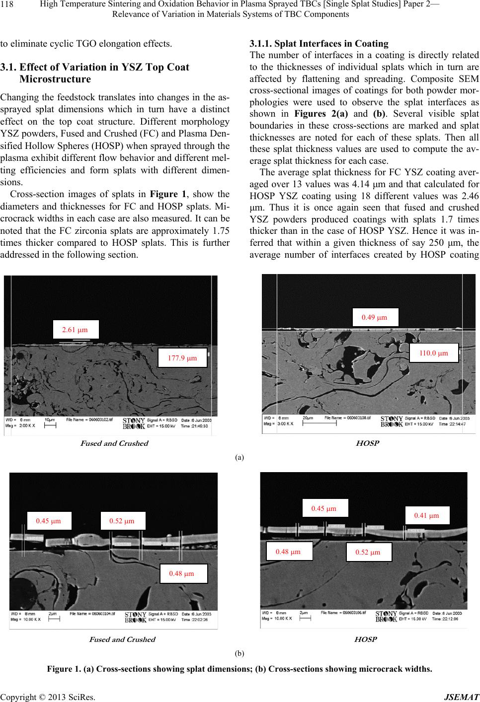 High Temperature Sintering and Oxidation Behavior in Plasma Sprayed TBCs [Single Splat Studies] Paper 2— Relevance of Variation in Materials Systems of TBC Components Copyright © 2013 SciRes. JSEMAT 118 3.1.1. Splat Interfaces in Coating to eliminate cyclic TGO elongation effects. The number of interfaces in a coating is directly related to the thicknesses of individual splats which in turn are affected by flattening and spreading. Composite SEM cross-sectional images of coatings for both powder mor- phologies were used to observe the splat interfaces as shown in Figures 2(a) and (b). Several visible splat boundaries in these cross-sections are marked and splat thicknesses are noted for each of these splats. Then all these splat thickness values are used to compute the av- erage splat thickness for each case. 3.1. Effect of Variation in YSZ Top Coat Microstructure Changing the feedstock translates into changes in the as- sprayed splat dimensions which in turn have a distinct effect on the top coat structure. Different morphology YSZ powders, Fused and Crushed (FC) and Plasma Den- sified Hollow Spheres (HOSP) when sprayed through the plasma exhibit different flow behavior and different mel- ting efficiencies and form splats with different dimen- sions. The average splat thickness for FC YSZ coating aver- aged over 13 values was 4.14 μm and that calculated for HOSP YSZ coating using 18 different values was 2.46 μm. Thus it is once again seen that fused and crushed YSZ powders produced coatings with splats 1.7 times thicker than in the case of HOSP YSZ. Hence it was in- ferred that within a given thickness of say 250 μm, the average number of interfaces created by HOSP coating Cross-section images of splats in Figure 1, show the diameters and thicknesses for FC and HOSP splats. Mi- crocrack widths in each case are also measured. It can be noted that the FC zirconia splats are approximately 1.75 times thicker compared to HOSP splats. This is further addressed in the following section. Fused and Crushe d HOS P 2.61 m 177.9 m 110.0 m 0.49 m (a) Fused and Crushe d HOS P 0.48 m 0.52 m 0.45 m 0.48 m 0.45 m 0.52 m 0.41 m (b) Figure 1. (a) Cross-sections showing splat dimensions; (b) Cross-sections showing microcrack widths. 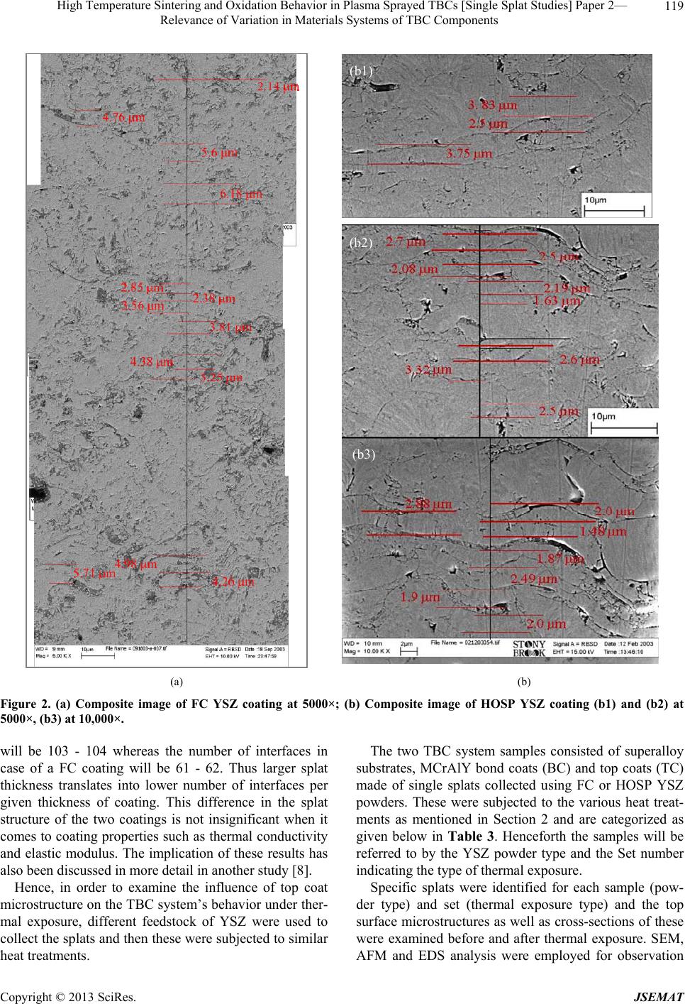 High Temperature Sintering and Oxidation Behavior in Plasma Sprayed TBCs [Single Splat Studies] Paper 2— Relevance of Variation in Materials Systems of TBC Components 119 (b1) (b2) (b3) (a) (b) Figure 2. (a) Composite image of FC YSZ coating at 5000×; (b) Composite image of HOSP YSZ coating (b1) and (b2) at 5000×, (b3) at 10,000×. will be 103 - 104 whereas the number of interfaces in case of a FC coating will be 61 - 62. Thus larger splat thickness translates into lower number of interfaces per given thickness of coating. This difference in the splat structure of the two coatings is not insignificant when it comes to coating properties such as thermal conductivity and elastic modulus. The implication of these results has also been discussed in more detail in another study [8]. Hence, in order to examine the influence of top coat microstructure on the TBC system’s behavior under ther- mal exposure, different feedstock of YSZ were used to collect the splats and then these were subjected to similar heat treatments. The two TBC system samples consisted of superalloy substrates, MCrAlY bond coats (BC) and top coats (TC) made of single splats collected using FC or HOSP YSZ powders. These were subjected to the various heat treat- ments as mentioned in Section 2 and are categorized as given below in Table 3. Henceforth the samples will be referred to by the YSZ powder type and the Set number indicating the type of thermal exposure. Specific splats were identified for each sample (pow- der type) and set (thermal exposure type) and the top surface microstructures as well as cross-sections of these were examined before and after thermal exposure. SEM, AFM and EDS analysis were employed for observation Copyright © 2013 SciRes. JSEMAT 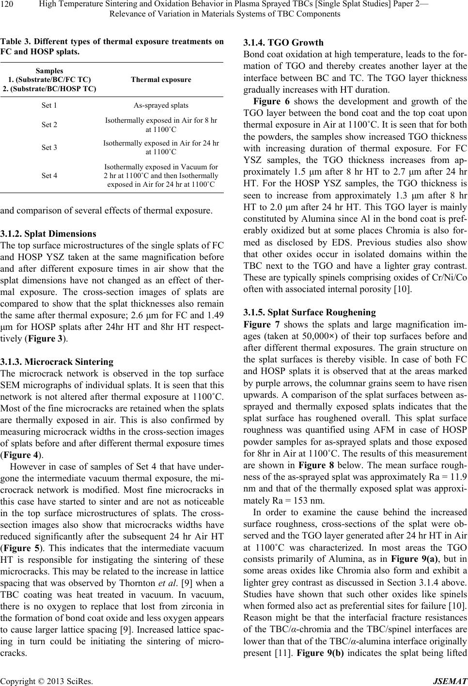 High Temperature Sintering and Oxidation Behavior in Plasma Sprayed TBCs [Single Splat Studies] Paper 2— Relevance of Variation in Materials Systems of TBC Components 120 Table 3. Different types of thermal exposure treatments on FC and HOSP splats. Samples 1. (Substrate/BC/FC TC) 2. (Substrate/BC/HOSP TC) Thermal exposure Set 1 As-sprayed splats Set 2 Isothermally exposed in Air for 8 hr at 1100˚C Set 3 Isothermally exposed in Air for 24 hr at 1100˚C Set 4 Isothermally exposed in Vacuum for 2 hr at 1100˚C and then Isothermally exposed in Air for 24 hr at 1100˚C and comparison of several effects of thermal exposure. 3.1.2. Splat Dimensions The top surface microstructures of the single splats of FC and HOSP YSZ taken at the same magnification before and after different exposure times in air show that the splat dimensions have not changed as an effect of ther- mal exposure. The cross-section images of splats are compared to show that the splat thicknesses also remain the same after thermal exposure; 2.6 μm for FC and 1.49 μm for HOSP splats after 24hr HT and 8hr HT respect- tively (Figure 3). 3.1.3. Microcrack Sintering The microcrack network is observed in the top surface SEM micrographs of individual splats. It is seen that this network is not altered after thermal exposure at 1100˚C. Most of the fine microcracks are retained when the splats are thermally exposed in air. This is also confirmed by measuring microcrack widths in the cross-section images of splats before and after different thermal exposure times (Figure 4). However in case of samples of Set 4 that have under- gone the intermediate vacuum thermal exposure, the mi- crocrack network is modified. Most fine microcracks in this case have started to sinter and are not as noticeable in the top surface microstructures of splats. The cross- section images also show that microcracks widths have reduced significantly after the subsequent 24 hr Air HT (Figure 5). This indicates that the intermediate vacuum HT is responsible for instigating the sintering of these microcracks. This may be related to the increase in lattice spacing that was observed by Thornton et al. [9] when a TBC coating was heat treated in vacuum. In vacuum, there is no oxygen to replace that lost from zirconia in the formation of bond coat oxide and less oxygen appears to cause larger lattice spacing [9]. Increased lattice spac- ing in turn could be initiating the sintering of micro- cracks. 3.1.4. TGO Growth Bond coat oxidation at high temperature, leads to the for- mation of TGO and thereby creates another layer at the interface between BC and TC. The TGO layer thickness gradually increases with HT duration. Figure 6 shows the development and growth of the TGO layer between the bond coat and the top coat upon thermal exposure in Air at 1100˚C. It is seen that for both the powders, the samples show increased TGO thickness with increasing duration of thermal exposure. For FC YSZ samples, the TGO thickness increases from ap- proximately 1.5 μm after 8 hr HT to 2.7 μm after 24 hr HT. For the HOSP YSZ samples, the TGO thickness is seen to increase from approximately 1.3 μm after 8 hr HT to 2.0 μm after 24 hr HT. This TGO layer is mainly constituted by Alumina since Al in the bond coat is pref- erably oxidized but at some places Chromia is also for- med as disclosed by EDS. Previous studies also show that other oxides occur in isolated domains within the TBC next to the TGO and have a lighter gray contrast. These are typically spinels comprising oxides of Cr/Ni/Co often with associated internal porosity [10]. 3.1.5. Splat Surface Roughening Figure 7 shows the splats and large magnification im- ages (taken at 50,000×) of their top surfaces before and after different thermal exposures. The grain structure on the splat surfaces is thereby visible. In case of both FC and HOSP splats it is observed that at the areas marked by purple arrows, the columnar grains seem to have risen upwards. A comparison of the splat surfaces between as- sprayed and thermally exposed splats indicates that the splat surface has roughened overall. This splat surface roughness was quantified using AFM in case of HOSP powder samples for as-sprayed splats and those exposed for 8hr in Air at 1100˚C. The results of this measurement are shown in Figure 8 below. The mean surface rough- ness of the as-sprayed splat was approximately Ra = 11.9 nm and that of the thermally exposed splat was approxi- mately Ra = 153 nm. In order to examine the cause behind the increased surface roughness, cross-sections of the splat were ob- served and the TGO layer generated after 24 hr HT in Air at 1100˚C was characterized. In most areas the TGO consists primarily of Alumina, as in Figure 9(a), but in some areas oxides like Chromia also form and exhibit a lighter grey contrast as discussed in Section 3.1.4 above. Studies have shown that such other oxides like spinels when formed also act as preferential sites for failure [10]. Reason might be that the interfacial fracture resistances of the TBC/α-chromia and the TBC/spinel interfaces are lower than that of the TBC/α-alumina interface originally present [11]. Figure 9(b) indicates the splat being lifted Copyright © 2013 SciRes. JSEMAT  High Temperature Sintering and Oxidation Behavior in Plasma Sprayed TBCs [Single Splat Studies] Paper 2— Relevance of Variation in Materials Systems of TBC Components Copyright © 2013 SciRes. JSEMAT 121 FC YSZ splat HOSP YSZ splat 2.61 m2.61 m2.61 m Set 3 (splat thickness) Set 1 (splat thickness) 2.6 m2.6 m2.6 m Set 3 Set 1 Set 2 Set 1 Set 2 Set 1 Set 3 Set 1 1.49 m1.49 m1.49 m1.49 m Set 2 (splat thickness) Set 1 (splat thickness) Figure 3. Splat dimensions before and after HT in Air@1100˚C (for FC and HOSP splats). FC YSZ spla t HOSP YSZ splat Set 2 (microcrack network) Set 1 (microcrack network) 0.52 m 0.48 m 0.45 m0.52 m 0.48 m 0.45 m Set 2 (microcrack width) Set 1 (microcrack width) 0. 48 m 0. 48 m0. 52 m 0. 48 m 0. 48 m0. 52 m Set 2 (microcrack network) Set 1 (microcrack network) Set 3(microcrack network) Set 1 (microcrack network) Set 3(microcrack network) Set 1 (microcrack network) Set 2 (microcrack width) Set 1 (microcrack width) 0.48 m0.52 m 0.45 m0.41 m 0.48 m0.52 m 0.45 m0.41 m 0.30 m 0.39 m 0.30 m 0.39 m Figure 4. Microcracks in splats before and after HT in Air@1100˚C (for FC and HOSP splats). 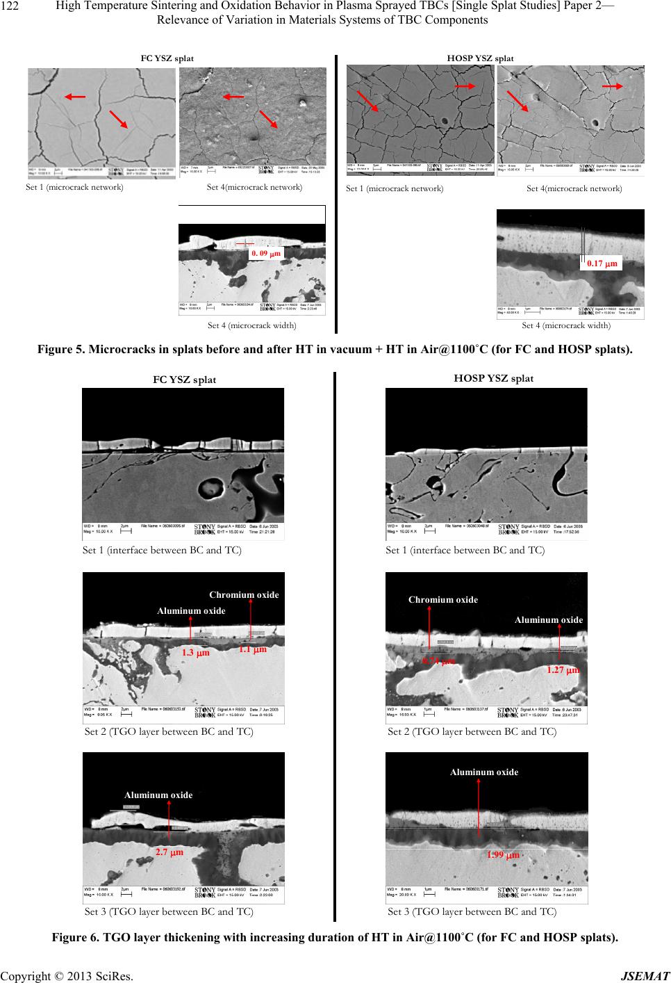 High Temperature Sintering and Oxidation Behavior in Plasma Sprayed TBCs [Single Splat Studies] Paper 2— Relevance of Variation in Materials Systems of TBC Components 122 Set 4(microcrack network) Set 1 (microcrack network) Set 4(microcrack network) Set 1 (microcrack network) FC YSZ splat HOSP YSZ splat 0. 09 m0. 09 m0. 09 m Set 4 (microcrack width)Set 4 (microcrack width) 0.17 m0.17 m Figure 5. Microcracks in splats before and after HT in vacuum + HT in Air@1100˚C (for FC and HOSP splats). FC YSZ splat HOSP YSZ splat Set 1 (interface between BC and TC) 1.3 m1.1 m Chromium oxide Aluminum oxide 1.3 m1.1 m Chromium oxide Aluminum oxide 2.7 m Aluminum oxide 2.7 m Aluminum oxide Set 2 (TGO layer between BC and TC) Set 3 (TGO layer between BC and TC) Set 1 (interface between BC and TC) Set 2 (TGO layer between BC and TC) Set 3 (TGO layer between BC and TC) Chromium oxide 1.27 m 0.74 m Aluminum oxide Chromium oxide 1.27 m 0.74 m Aluminum oxide Aluminum oxide 1.99 m Aluminum oxide 1.99 m Figure 6. TGO layer thickening with increasing duration of HT in Air@1100˚C (for FC and HOSP splats). Copyright © 2013 SciRes. JSEMAT 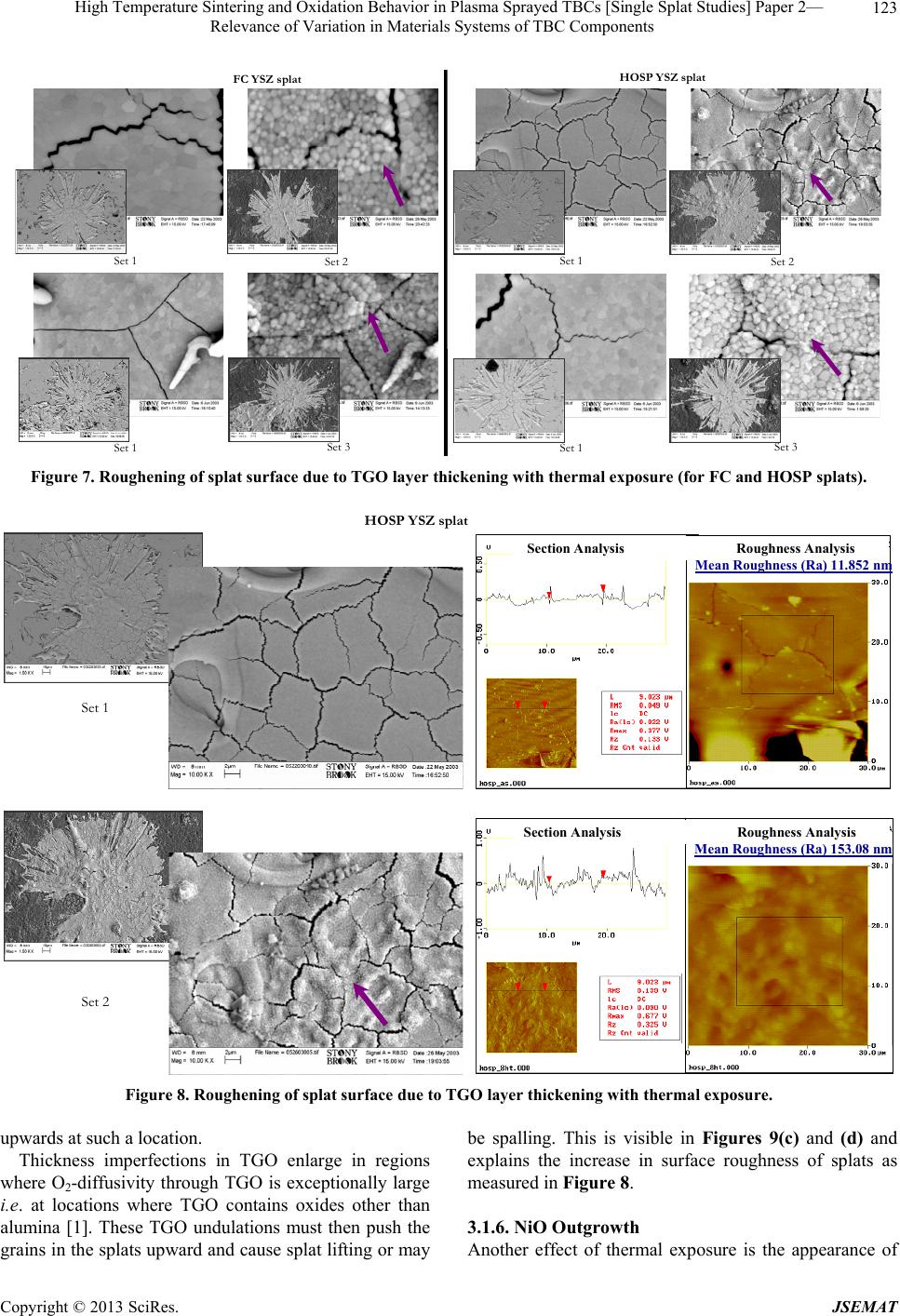 High Temperature Sintering and Oxidation Behavior in Plasma Sprayed TBCs [Single Splat Studies] Paper 2— Relevance of Variation in Materials Systems of TBC Components Copyright © 2013 SciRes. JSEMAT 123 FC YSZ splat HOSP YSZ splat Set 3 Set 1 Set 2 Set 1 Set 3 Set 1 Set 2 Set 1 Figure 7. Roughening of splat surface due to TGO layer thickening w i th ther mal exposure (for FC and HOSP splats). HOSP YSZ splat Section AnalysisRoughness Analys is Mean Roughness (Ra) 11.852 nm Section AnalysisRoughness Analys is Mean Roughness (Ra) 11.852 nm Secti on A nalysisRoughnes s Analys is Mean Roughness (Ra) 153.08 nm Secti on A nalysisRoughnes s Analys is Mean Roughness (Ra) 153.08 nm Set 2 Set 1 Figure 8. Roughening of splat surface due to TGO layer thickening with thermal exposure. upwards at such a location. Thickness imperfections in TGO enlarge in regions where O2-diffusivity through TGO is exceptionally large i.e. at locations where TGO contains oxides other than alumina [1]. These TGO undulations must then push the grains in the splats upward and cause splat lifting or may be spalling. This is visible in Figures 9(c) and (d) and explains the increase in surface roughness of splats as measured in Figure 8. 3.1.6. NiO O utgrowth A nother effect of thermal exposure is the appearance of 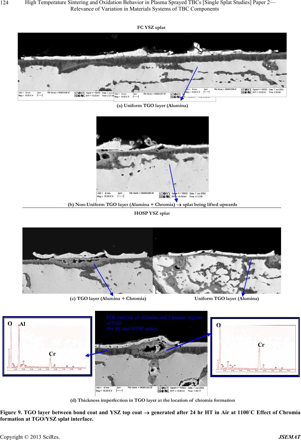 High Temperature Sintering and Oxidation Behavior in Plasma Sprayed TBCs [Single Splat Studies] Paper 2— Relevance of Variation in Materials Systems of TBC Components 124 (b) Non-Uniform TGO layer (Alumina + Chromia) splat being lifted upwards (a) Uniform TGO layer (Alumina) FC YSZ splat (c) TGO layer (Alumina + Chromia) Uniform TGO layer (Alumina) Cr O Cr O Cr OAl Cr OAl EDS analysis of Alumina and Chromia regions of TGO (for FC and HOSP splats) (d) Thickness imperfection in TGO layer at the location of chromia formation HOSP YSZ splat Figure 9. TGO layer between bond coat and YSZ top coat generated after 24 hr HT in Air at 1100˚C Effect of Chromia ormation at TGO/YSZ splat interface. f Copyright © 2013 SciRes. JSEMAT 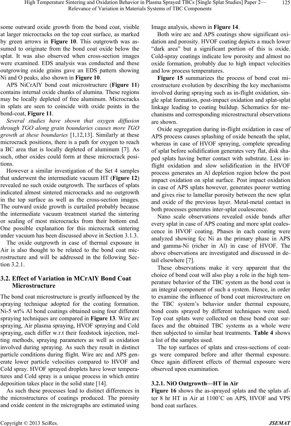 High Temperature Sintering and Oxidation Behavior in Plasma Sprayed TBCs [Single Splat Studies] Paper 2— Relevance of Variation in Materials Systems of TBC Components 125 some outward oxide growth from the bond coat, visible at larger microcracks on the top coat surface, as marked by green arrows in Figure 10. This outgrowth was as- sumed to originate from the bond coat oxide below the splat. It was also observed when cross-section images were examined. EDS analysis was conducted and these outgrowing oxide grains gave an EDS pattern showing Ni and O peaks, also shown in Figure 10. APS NiCrAlY bond coat microstructure (Figure 11) contains internal oxide chunks of alumina. These regions may be locally depleted of free aluminum. Microcracks in splats are seen to coincide with oxide points in the bond-coat, Figure 11. Several studies have shown that oxygen diffusion through TGO along grain boundaries causes more TGO growth at these boundaries [1,12,13]. Similarly at these microcrack positions, there is a path for oxygen to reach a BC area that is locally depleted of aluminum [7]. As such, other oxides could form at these microcrack posi- tions. However a similar investigation of the Set 4 samples that underwent the intermediate vacuum HT (Figure 12) revealed no such oxide outgrowth. The surfaces of splats indicated almost sintered microcracks and no outgrowth in the top surface as well as the cross-section images. The outward oxide growth is curtailed probably because the intermediate vacuum treatment started the sintering or sealing of most microcracks from their bottom end. One possible explanation for this microcrack sintering under vacuum has been discussed above in Section 3.1.3. The oxide outgrowth in case of thermal exposure in Air is also thought to be related to the bond coat mic- rostructure and will be addressed in the following Sec- tion 3.2.1. 3.2. Effect of Variation in MCrAlY Bond Coat Microstructure The bond coat microstructure is greatly influenced by the spraying technique adopted for the coating formation. Ni-5 wt% Al bond coatings obtained using four different spraying techniques are compared in Figure 13. Wire arc spraying, Air plasma spraying, HVOF spraying and Cold spraying, each differ w.r.t their feedstock injection, mel- ting methods, spraying parameters as well as oxidation involved during spraying. As such they result in distinct particle conditions during flight. Wire arc and APS gen- erate lower particle velocities compared to HVOF and Cold spray. HVOF sprayed droplets have lower tempera- tures and Cold spray is a unique process in which entire deposition takes place in the solid state [14]. As such these processes lead to distinct differences in the microstructures of coatings produced. The porosity and oxide content in the micrographs are estimated using Image analysis, shown in Figure 14. Both wire arc and APS coatings show significant oxi- dation and porosity. HVOF coating depicts a much lower “dark area” but a significant portion of this is oxide. Cold-spray coatings indicate low porosity and almost no oxide formation, probably due to high impact velocities and low process temperatures. Figure 15 summarizes the process of bond coat mi- crostructure evolution by describing the key mechanisms involved during spraying such as in-flight oxidation, sin- gle splat formation, post-impact oxidation and splat-splat linkage leading to coating buildup. Schematics for me- chanisms and corresponding microstructural observations are shown. Oxide segregation during in-flight oxidation in case of APS process causes splashing of oxide beneath the splat, whereas in case of HVOF spraying, complete spreading of splat before solidification generates very flat, disk sha- ped splats having better contact with substrate. Less in- flight oxidation and slow solidification in the HVOF process generates an Al depletion region below the post impact oxidation on splat surface. Post impact oxidation in case of APS splats however, generates poorer wetting and gives rise to lamellar porosity between the new splat and oxide of the previous layer. Metal-metal contact in both processes generates inter-splat coalescence. Nano scale observations revealed oxide bands after every splat in case of APS coating and more splat coales- cence in HVOF coating. Phases in each coating were analyzed showing fcc Ni as the primary phase in APS and gamma-Ni (richer in Al) in case of HVOF. The above observations are investigated and discussed in de- tail elsewhere [7]. These observations make it very apparent that the choice of bond coat will also play a role in the high tem- perature behavior of the TBC system as the bond coat is an integral component of such a system. Hence, in order to examine the influence of bond coat microstructure on the TBC system’s behavior under thermal exposure, bond coats sprayed by different techniques were used. Top coat splats were collected on these bond coat sur- faces and the obtained TBC systems as a whole were then subjected to similar heat treatments. Table 4 shows a list of the samples used. The top surfaces of splats and cross-sections of coat- gs were compared before and after thermal exposure. Once again different effects of thermal exposure were observed upon examination. 3.2.1. Ni O Outgrowth—HT in Air Figure 16 shows the as-sprayed splats and the splats af- ter 8 hr HT in Air at 1100˚C on APS, HVOF and VPS bond coat surfaces. Copyright © 2013 SciRes. JSEMAT 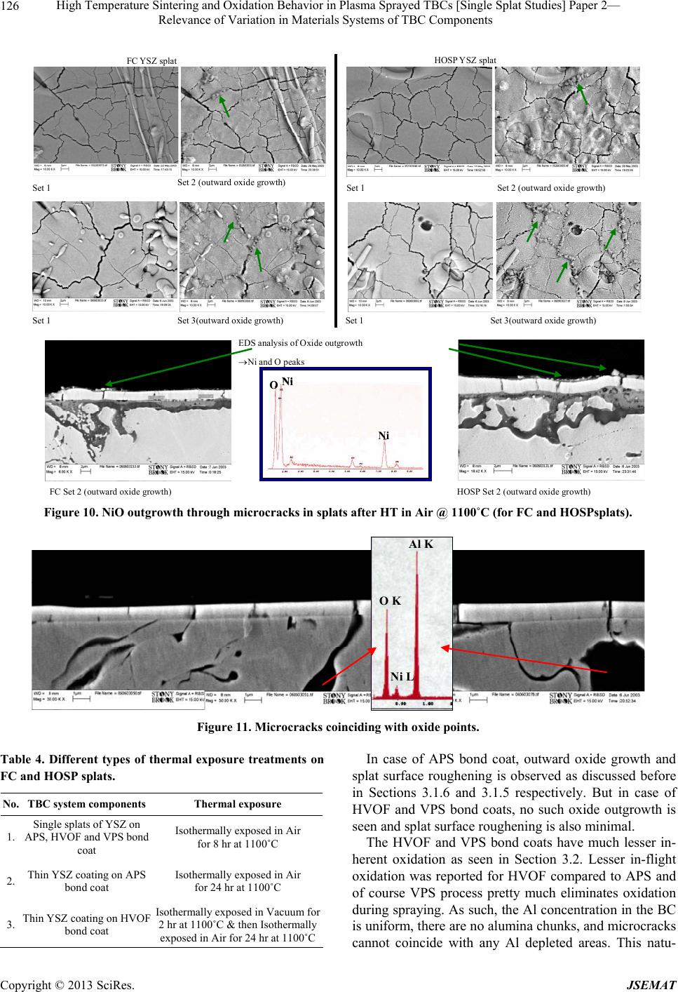 High Temperature Sintering and Oxidation Behavior in Plasma Sprayed TBCs [Single Splat Studies] Paper 2— Relevance of Variation in Materials Systems of TBC Components 126 FC YSZ spla t HOSP YSZ spla t Set 1 Set 2 (outward oxide growth) Set 3(outward oxide growth) Set 1 Set 2 (outward oxide growth) Set 1 Set 3(outward oxide growth) Set 1 EDS analysis of Oxide outgrowth Ni and O peaks FC Set 2 (outward oxide growth) HOSP Set 2 (outward oxide growth) Ni Ni ONi Ni O Figure 10. NiO outgrowth through microcracks in splats after HT in Air @ 1100˚C (for FC and HOSPsplats). O K Al K Ni L O K Al K Ni L Figure 11. Microcracks coinciding with oxide points. Table 4. Different types of thermal exposure treatments on FC and HOSP splats. No. TBC system components Thermal exposure 1. Single splats of YSZ on APS, HVOF and VPS bond coat Isothermally exposed in Air for 8 hr at 1100˚C 2. Thin YSZ coating on APS bond coat Isothermally exposed in Air for 24 hr at 1100˚C 3. Thin YSZ coating on HVOF bond coat Isothermally exposed in Vacuum for 2 hr at 1100˚C & then Isothermally exposed in Air for 24 hr at 1100˚C In case of APS bond coat, outward oxide growth and splat surface roughening is observed as discussed before in Sections 3.1.6 and 3.1.5 respectively. But in case of HVOF and VPS bond coats, no such oxide outgrowth is seen and splat surface roughening is also minimal. The HVOF and VPS bond coats have much lesser in- herent oxidation as seen in Section 3.2. Lesser in-flight oxidation was reported for HVOF compared to APS and of course VPS process pretty much eliminates oxidation during spraying. As such, the Al concentration in the BC is uniform, there are no alumina chunks, and microcracks cannot coincide with any Al depleted areas. This natu- Copyright © 2013 SciRes. JSEMAT 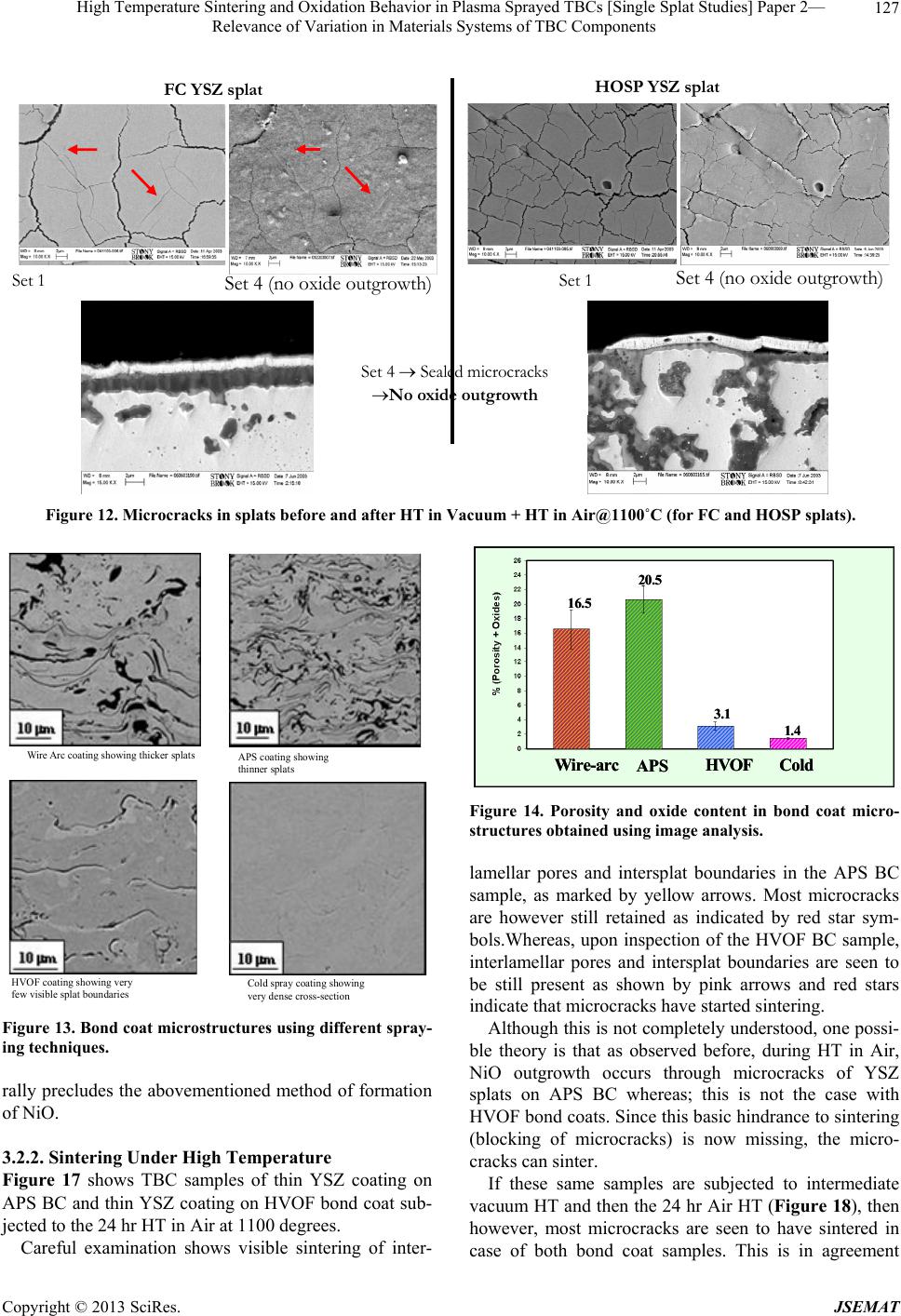 High Temperature Sintering and Oxidation Behavior in Plasma Sprayed TBCs [Single Splat Studies] Paper 2— Relevance of Variation in Materials Systems of TBC Components 127 Set 4 Sealed microcracks No oxide outgrowth FC YSZ splat HOSP YSZ splat Set 1 Set 4 (no oxide outgrowth) Set 1 Set 4 (no oxide outgrowth) Figure 12. Microcracks in splats before and after HT in Vacuum + HT in Air@1100˚C (for FC and HOSP splats). APS coating showing thinner splats Cold spray coating showing very dense cross-section Wire Arc coating showing thicker splats HVOF coating showing very few visible splat boundaries Figure 13. Bond coat microstructures using different spray- ing techniques. rally precludes the abovementioned method of formation of NiO. 3.2.2. Sintering Under High Temperature Figure 17 shows TBC samples of thin YSZ coating on APS BC and thin YSZ coating on HVOF bond coat sub- jected to the 24 hr HT in Air at 1100 degrees. Careful examination shows visible sintering of inter- Wire-arc APS HVOF Cold 16.5 20.5 3.1 1.4 Wire-arc APS HVOF Cold 16.5 20.5 3.1 1.4 Wire-arc APS HVOF Cold 16.5 20.5 3.1 1.4 Figure 14. Porosity and oxide content in bond coat micro- structures obtained using image analysis. lamellar pores and intersplat boundaries in the APS BC sample, as marked by yellow arrows. Most microcracks are however still retained as indicated by red star sym- bols.Whereas, upon inspection of the HVOF BC sample, interlamellar pores and intersplat boundaries are seen to be still present as shown by pink arrows and red stars indicate that microcracks have started sintering. Although this is not completely understood, one possi- ble theory is that as observed before, during HT in Air, NiO outgrowth occurs through microcracks of YSZ splats on APS BC whereas; this is not the case with HVOF bond coats. Since this basic hindrance to sintering (blocking of microcracks) is now missing, the micro- cracks can sinter. If these same samples are subjected to intermediate vacuum HT and then the 24 hr Air HT (Figure 18), then however, most microcracks are seen to have sintered in ase of both bond coat samples. This is in agreement c Copyright © 2013 SciRes. JSEMAT  High Temperature Sintering and Oxidation Behavior in Plasma Sprayed TBCs [Single Splat Studies] Paper 2— Relevance of Variation in Materials Systems of TBC Components 128 APS bond coat HVOF bond coat Internal oxide, Al2O3 Internal oxide, Al2O3 Oxide segregation Al2O3 Oxide segregation Al2O3 SubstrateSubstrate SubstrateSubstrateSubstrateSubstrate SubstrateSubstrateSubstrateSubstrate SubstrateSubstrateSubstrateSubstrate SubstrateSubstrateSubstrateSubstrate Oxide splashing beneath splat [1] Oxide splashing beneath splat Oxide splashing beneath splat [1] Complete spreading of splat before solidificationComplete spreading of splat before solidification 5 m5 m [2] Al depletion below oxide [2] Al depletion below oxide Coalescence between two metal splats with no oxide in between Coalescence between two metal splats with no oxide in between Lamellar pore between new splat and oxide of previous layer [3] Lamellar pore between new splat and oxide of previous layer [3] 2 m2 m2 m2 m Substrate Oxide growing on top of splat SubstrateSubstrateSubstrateSubstrate Oxide growing on top of splat Oxide bands after every splat [4] Oxide bands after every splat [4] More splat coalescence [5] More splat coalescence [5] [6] Ni (200) Ni (020)Ni (2 20) fcc Ni [6] Ni (200) Ni (020)Ni (2 20) fcc Ni Ni (200) Ni (020)Ni (2 20) Ni (200) Ni (022) Ni (311) Ni (200) Ni (020)Ni (2 20) Ni (200) Ni (020)Ni (2 20)Ni (111) fcc NiNi Ni (200) Ni (022) Ni (311) Ni (111) Ni (200) Ni (022) Ni (311) Ni (111) Ni (200) Ni (022) Ni (311) Ni (111) Ni (111) Ni (311) Ni Figure 15. Bond coat microstructure evolution—influence of spray process. APS bond coat HVOF bond coat VPS bond coat Set 1 Set 2 (splat surface roughening and oxide outgrowth) Set 1 Set 2 (no splat surface roughening and no oxide outgrowth) Set 1 Set 2 (less splat surface roughening, no oxide outgrowth) Figure 16. Effects on top coat single splats after 8 hr HT in Air@1100˚C (for APS, HVOF and VPOS bond coats). Copyright © 2013 SciRes. JSEMAT  High Temperature Sintering and Oxidation Behavior in Plasma Sprayed TBCs [Single Splat Studies] Paper 2— Relevance of Variation in Materials Systems of TBC Components 129 APS bond coat HVOF bond coat * * Set 3 (interlamellar boundaries and microcracks) Set 3 (interlamellar boundaries and microcracks) * * * Figure 17. Sintering in top coat after 24 hr HT in Air@1100˚C (for APS and HVOF bond coats). Set 4 (interlamellar boundaries and microcracks) APS bond coat HVOF bond coat Set 4 (interlamellar boundaries and microcracks) Figure 18. Sintering in top coat after 2 hr HT in Vacuum + 24 hr HT in Air@1100˚C (for APS and HVOF bond coats). with the previous observations made in case of single splats. 3.2.3. TGO Growth The TGO formation in these samples with different bond coats was also considered and is illustrated in Figure 19. For the same duration of HT i.e. 24 hr in Air at 1100 de- grees, APS bond coat shows faster TGO growth than HVOF bond coat. The TGO thickness is seen to be 2.7 μm for APS bond coat sample and 1.7 μm for the HVOF bond coat sample. 3.2.4. TGO Imperfections When the elemental composition along the TGO in both samples is compared, then for the APS bond coat sample, many locations along the TGO length show formation of Copyright © 2013 SciRes. JSEMAT  High Temperature Sintering and Oxidation Behavior in Plasma Sprayed TBCs [Single Splat Studies] Paper 2— Relevance of Variation in Materials Systems of TBC Components 130 other oxides like Chromia.However, for the HVOF bond coat sample, although some locations show TGO thick- ening, chromia formation is not visible. This is clearly shown in Figure 20. Once again this is related to inherent oxidation levels in both bond coats. APS bond coats have undergone more oxidation during their formation and hence have lesser free Al available for TGO formation. Al depletion 2.7 m2.7 m 1.7 m1.7 m APS bond coat HVOF bond coa t Figure 19. TGO growth after 24 hr HT in Air@1100˚C (for APS and HVOF bond coats). Set 4 (TGO layer at BC/TC interface) APS bond coat HVOF bond coat Set 4 (TGO layer at BC/TC interface) Locations of Chromia formation T GO thickening but no Chromia formation Figure 20. Thickness imperfec tions in TGO—thicke ning and for m ation of othe r oxide s (for APS and HVOF bond coats). Copyright © 2013 SciRes. JSEMAT  High Temperature Sintering and Oxidation Behavior in Plasma Sprayed TBCs [Single Splat Studies] Paper 2— Relevance of Variation in Materials Systems of TBC Components 131 in BC causes other oxides to form, as also shown by Tolpygo and Clarke [15,16]. HVOF bond coats have more free Al retained in the coating and hence they have a longer way to go before Al depletion occurs. Fewer instances of chromia formation means fewer occurrences of thickness imperfections in the TGO layer and hence reduced splat surface roughening in case of HVOF and VPS bond coats. This further explains the observations in Figure 16, Section 3.2.1. 4. Conclusions In this study, the following effects of thermal exposure were considered and compared as an outcome of varia- tions in top coat splat dimensions and bond coat micro- structures. Microcracks sintering in splats. TGO growth at interface between top coat and bond coat. Splat surface roughening. NiO outgrowth occurring through microcracks in splats. Effect of intermediate Vacuum HT during thermal exposure. It was seen that in case of top coat, different YSZ feedstock give different initial splat dimensions in the as-sprayed splats but the splats show the same high tem- perature behavior when subjected to similar heat treat- ments. Intermediate vacuum heat treatment alters the microcrack sintering behavior observed for Air heat treatment and also prevents the NiO outgrowth upon thermal exposure. But these effects are also similar for both YSZ powders. So, the top coat microstructure with respect to single splats does not have an influence on high temperature behavior of the system. In case of bond coats, however, when different spray- ing techniques are used, the inherent oxidation levels in the bond coat microstructures are different and this does influence the behavior of the system upon high tempera- ture exposure. The free Al available in the BC for TGO formation dictates the occurrence of chromia formation and hence determines the extent of TGO thickness imperfections leading to splat surface roughening or spallation. Absence of Alumina chunks in the HVOF and VPS bond coat microstructures prevents the described method of formation of NiO outgrowth through microcracks and stimulates microcracks sintering which is not observed in APS bond coats under similar thermal exposure. 5. Acknowledgements We would like to thank Glenn Bancke, AnirudhaVaidya, John Gutleber and Li Li (CTSR) for preparation of the specimens and spraying diagnostics. REFERENCES [1] A. G. Evans, D. R. Mumm, J. W. Hutchinson, G. H. Meier and F. S. Pettit, “Mechanisms Controlling the Du- rability of Thermal Barrier Coatings,” Progress in Mate- rials Science, Vol. 46, No. 5, 2001, pp. 505-553. doi:10.1016/S0079-6425(00)00020-7 [2] A. Nusair Khan and J. Lu, “Behavior of Air Plasma Sprayed Thermal Barrier Coatings, Subject to Intense Thermal Cycling,” Surface and Coatings Technology, Vol. 166, No. 1, 2003, pp. 37-43. doi:10.1016/S0257-8972(02)00740-5 [3] A. Rabiei and A. G. Evans, “Failure Mechanisms Associ- ated with the Thermally Grown Oxide in Plasma Sprayed Thermal Barrier Coatings,” Acta Materialia, Vol. 48, No. 15, 2000, pp. 3963-3976. doi:10.1016/S1359-6454(00)00171-3 [4] A. Kulkarni, S. Sampath, A. Goland and H. Herman, “Porosity-Thermal Conductivity Relationships in Plasma Sprayed Zirconia Coatings,” In: C. C. Berndt, Ed., Ther- mal Spray: Surface Engineering via Applied Research (ITSC 2000), ASM International, Materials Park, Mont- real, 8-11 May 2000, pp. 1061-1066. [5] A. Kulkarni, Z. Wang, T. Nakamura, S. Sampath, A. Go- land, H. Herman, A. J. Allen, J. Ilavsky, G. Long, J. Frahm and R. W. Steinbrech,“Comprehensive Micro- structural Characterization and Predictive Property Mod- eling of Plasma-Sprayed Zirconia Coatings,” Acta Mate- rialia, Vol. 51, No. 9, 2003, pp. 2457-2475. doi:10.1016/S1359-6454(03)00030-2 [6] S. Deshpande, A. Kulkarni, S. Sampath and H. Herman, “Application of Image Analysis for characterization of Porosity in Thermal Spray Coatings and Correlation with Small Angle Neutron Scattering,” Surface and Coatings Technology, Vol. 187, No. 1, 2004, pp. 6-16. doi:10.1016/j.surfcoat.2004.01.032 [7] S. Deshpande, S. Sampath and H. Zhang, “Mechanisms of Oxidation and Its Role in Microstructural Evolution of Metallic Thermal Spray Coatings—Case study for NiAl,” Surface and Coatings Technology, Vol. 200, No. 18-19, 2006, pp. 5395-5406. doi:10.1016/j.surfcoat.2005.07.072 [8] Z. Wang, A. Kulkarni, S. Deshpande, T. Nakamura and H. Herman, “Computational Approaches to Estimate Proper- ties of Thermally Sprayed Porous Coatings,” Acta Mate- rialia, Vol. 51, No. 18, 2003, pp. 5319-5334. doi:10.1016/S1359-6454(03)00390-2 [9] J. Thornton, D. Cookson and E. Pescott, “The Measure- ment of Strains within the bulk of Aged and As-Sprayed Thermal Barrier Coatings Using Synchrotron Radiation,” Surface and Coatings Technology, Vol. 120-121, 1999, pp. 96-102. doi:10.1016/S0257-8972(99)00340-0 [10] A. Rabiei and A. G. Evans, “Failure Mechanisms Associ- ated with the Thermally Grown Oxide in Plasma Sprayed Thermal Barrier Coatings,” Acta Materialia, Vol. 48, No. 15, 2000, pp. 3963-3976. doi:10.1016/S1359-6454(00)00171-3 Copyright © 2013 SciRes. JSEMAT  High Temperature Sintering and Oxidation Behavior in Plasma Sprayed TBCs [Single Splat Studies] Paper 2— Relevance of Variation in Materials Systems of TBC Components 132 [11] E. A. G. Shillington and D. R. Clarke, “Spalling Failure of a Thermal Barrier Coating Associated with Aluminum Depletion in the Bond-Coat,” Acta Materialia, Vol. 47, No. 4, 1999, pp. 1297-1305. doi:10.1016/S1359-6454(98)00407-8 [12] T. Xu, M. Y. He and A. G. Evans, “A Numerical As- sessment of the Durability of Thermal Barrier Systems That Fail by Ratcheting of the Thermally Grown Oxide,” Acta Materialia, Vol. 51, No. 13, 2003, pp. 3807-3820. doi:10.1016/S1359-6454(03)00194-0 [13] A. M. Karlsson, J. W. Hutchinson and A. G. Evans, “The Displacement of the Thermally Grown Oxide in Thermal Barrier Systems upon Thermal Cycling,” Materials Sci- ence and Engineering, Vol. 35, No. 1-2, 2003, pp. 244- 257. doi:10.1016/S0921-5093(02)00843-2 [14] S. Deshpande, S. Sampath, P. I. Gouma and H. Herman, “Microstructural Characterization across Length Scales of Thermal Sprayed Ni5wt%Al Coatings,” In: B. R. Marple, Ed., Thermal Spray: Advancing the Science and Applying the Technology (ITSC 2003), ASM International, Material Park, Orlando, 5-8 May 2003, pp. 1419-1428. [15] R. Panat, S. Zhang and K. J. Hsia, “Bond Coat Surface Rumpling in Thermal Barrier Coatings,” Acta Materialia, Vol. 51, No. 1, 2003, pp. 239-249. [16] V. K. Tolpygo and D. R. Clarke, “Surface Rumpling of a (Ni,Pt)Al Bond Coatinduced by Cyclic Oxidation,” Acta Materialia, Vol. 48, No. 13, 2000, pp. 3283-3293. doi:10.1016/S1359-6454(00)00156-7 Copyright © 2013 SciRes. JSEMAT |