

Paper Menu >>
Journal Menu >>
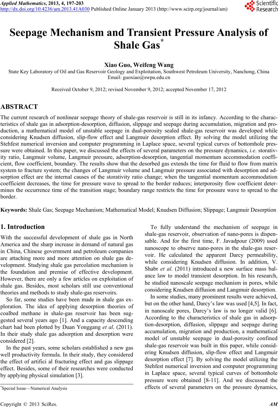 Applied Mathematics, 2013, 4, 197-203 http://dx.doi.org/10.4236/am.2013.41A030 Published Online January 2013 (http://www.scirp.org/journal/am) Seepage Mechanism and Transient Pressure Analysis of Shale Gas* Xiao Guo, Weifeng Wang State Key Laboratory of Oil and Gas Reservoir Geology and Exploitation, Southwest Petroleum University, Nanchong, China Email: [email protected] Received October 9, 2012; revised November 9, 2012; accepted November 17, 2012 ABSTRACT The current research of nonlinear seepage theory of shale-gas reservoir is still in its infancy. According to the charac- teristics of shale gas in adsorption-desorption, diffusion, slippage and seepage during accumulation, migration and pro- duction, a mathematical model of unstable seepage in dual-porosity sealed shale-gas reservoir was developed while considering Knudsen diffusion, slip-flow effect and Langmuir desorption effect. By solving the model utilizing the Stehfest numerical inversion and computer programming in Laplace space, several typical curves of bottomhole pres- sure were obtained. In this paper, we discussed the effects of several parameters on the pressure dynamics, i.e. storativ- ity ratio, Langmuir volume, Langmuir pressure, adsorption-desorption, tangential momentum accommodation coeffi- cient, flow coefficient, boundary. The results show that the desorbed gas extends the time for fluid to flow from matrix system to fracture system; the changes of Langmuir volume and Langmuir pressure associated with desorption and ad- sorption effect are the internal causes of the storativity ratio change; when the tangential momentum accommodation coefficient decreases, the time for pressure wave to spread to the border reduces; interporosity flow coefficient deter- mines the occurrence time of the transition stage; boundary range restricts the time for pressure wave to spread to the border. Keywords: Shale Gas; Seepage Mechanism; Mathematical Model; Knudsen Diffusion; Slippage; Langmuir Desorption 1. Introduction With the successful development of shale gas in North America and the sharp increase in demand of natural gas in China, Chinese government and petroleum companies are attaching more and more attention on shale gas de- velopment. Studying shale gas percolation mechanism is the foundation and premise of effective development. However, there are only a few articles on exploitation of shale gas. Besides, most scholars still use conventional theories and methods to study shale-gas reservoirs. So far, some studies have been made in shale gas ex- ploration. The idea of applying desorption theories of coalbed methane in shale-gas reservoir has been sug- gested several years ago [1]. And a capacity descending chart had been plotted by Duan Yonggang et al. (2011). In their study shale gas adsorption and desorption were considered [2]. In the past years, some scholars established a new gas well productivity formula. In their study, they considered the effect of artifici al fracturing effect and gas slippage effect. Besides, some of their researches were conducted by applying physical simulation [3]. To fully understand the mechanism of seepage in shale-gas reservoir, observation of nano-pores is dispen- sable. And for the first time, F. Javadpour (2009) used nanoscope to observe nano-pores in the shale-gas reser- voir. He calculated the apparent Darcy permeability, while considering Knudsen diffusion. In addition, V. Shabr et al. (2011) introduced a new surface mass bal- ance law to model transient desorption. In his research, he studied nanoscale seepage mechanism in pores, while considering Knudsen diffusion and Langmuir desorption. In some studies, many prominent results were achieved, but on the other hand, Darcy’s law was used [4,5]. In fact, in nanoscale pores, Darcy’s law is no longer valid [6]. According to the characteristics of shale gas in adsorp- tion-desorption, diffusion, slippage and seepage during accumulation, migration and production, a mathematical model of unstable seepage in dual-porosity confined shale-gas reservoir was built in this paper, while consid- ering Knudsen diffusion, slip-flow effect and Langmuir desorption effect [7]. By solving the model utilizing the Stehfest numerical inversion and computer programming in Laplace space, several typical curves of bottomhole pressure were obtained [8-11]. And we discussed the effects of several parameters on the pressure dynamics, *Special Issue—Numerical Analysis C opyright © 2013 SciRes. AM 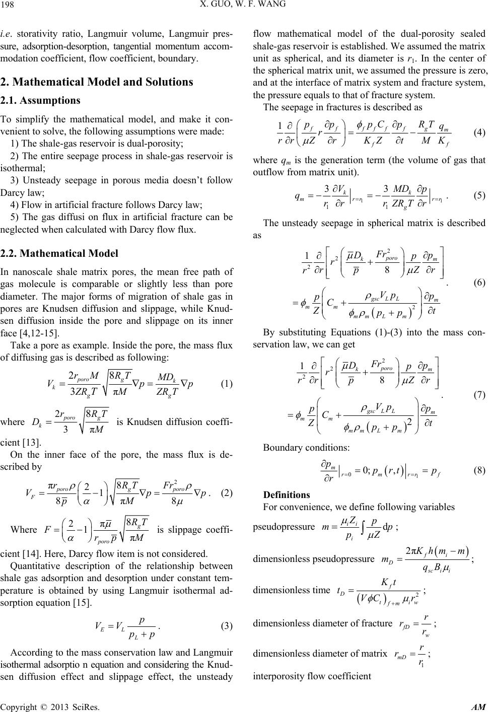 X. GUO, W. F. WANG 198 i.e. storativity ratio, Langmuir volume, Langmuir pres- sure, adsorption-desorption, tangential momentum accom- modation coefficient, flow coefficient, boundary. 2. Mathematical Model and Solutions 2.1. Assumptions To simplify the mathematical model, and make it con- venient to solve, the following assumptions were made: 1) The shale-gas reservoir is dual-porosity; 2) The entire seepage process in shale-gas reservoir is isothermal; 3) Unsteady seepage in porous media doesn’t follow Darcy law; 4) Flow in artificial fracture follows Darcy law; 5) The gas diffusi on flux in artificial fracture can be neglected when calculated with Darcy flow flux. 2.2. Mathematical Model In nanoscale shale matrix pores, the mean free path of gas molecule is comparable or slightly less than pore diameter. The major forms of migration of shale gas in pores are Knudsen diffusion and slippage, while Knud- sen diffusion inside the pore and slippage on its inner face [4,12-15]. Take a pore as example. Inside the pore, the mass flux of diffusing gas is described as following: π 28 3 poro gk k gg rM RTMD Vp ZRMZR T T p (1) where 2 3π 8 poro g k rR DT M is Knudsen diffusion coeffi- cient [13]. On the inner face of the pore, the mass flux is de- scribed by 2 π8 21 8π8 porog poro F rRTFr Vp pM p . (2) Where 8 2π 1π g poro RT Frp M is slippage coeffi- cient [14]. Here, Darcy flow item is not considered. Quantitative description of the relationship between shale gas adsorption and desorption under constant tem- perature is obtained by using Langmuir isothermal ad- sorption equation [15]. EL L p VV pp . (3) According to the mass conservation law and Langmuir isothermal adsorptio n equation and considering the Knud- sen diffusion effect and slippage effect, the unsteady flow mathematical model of the dual-porosity sealed shale-gas reservoir is established. We assumed the matrix unit as spherical, and its diameter is r1. In the center of the spherical matrix unit, we assumed the pressure is zero, and at the interface of matrix system and fracture system, the pressure equals to that of fracture system. The seepage in fractures is described as 1ff ffffg m f f pp pCpRT q r rr ZrKZtMK (4) where qm is the generation term (the volume of gas that outflow from matrix unit). 11 11 33 kk mrr g VMD p qrr rZRTr rr . (5) The unsteady seepage in spherical matrix is described as 2 2 2 2 1 8 poro km gsc LLm mm mm Lm Fr Dp p r rp Zr r Vp p pC Z t pp . (6) By substituting Equations (1)-(3) into the mass con- servation law, we can get 2 2 2 1 8 2 poro km gsc LLm mm mm Lm Fr Dp p r rp Zr r Vp p pC Z t pp . (7) Boundary conditions: 1 00; , m rmrr pprtp r f (8) Definitions For convenience, we define following variables pseudopressure d ii i Zp mp pZ ; dimensionless pseudopressure 2πfi D sc i i K hm m mqB ; dimensionless time 2 f D ti fm Kt tVC r w ; dimensionless diameter of fracture fD w r rr ; dimensionless diameter of matrix 1 mD r rr ; interporosity flow coefficient Copyright © 2013 SciRes. AM 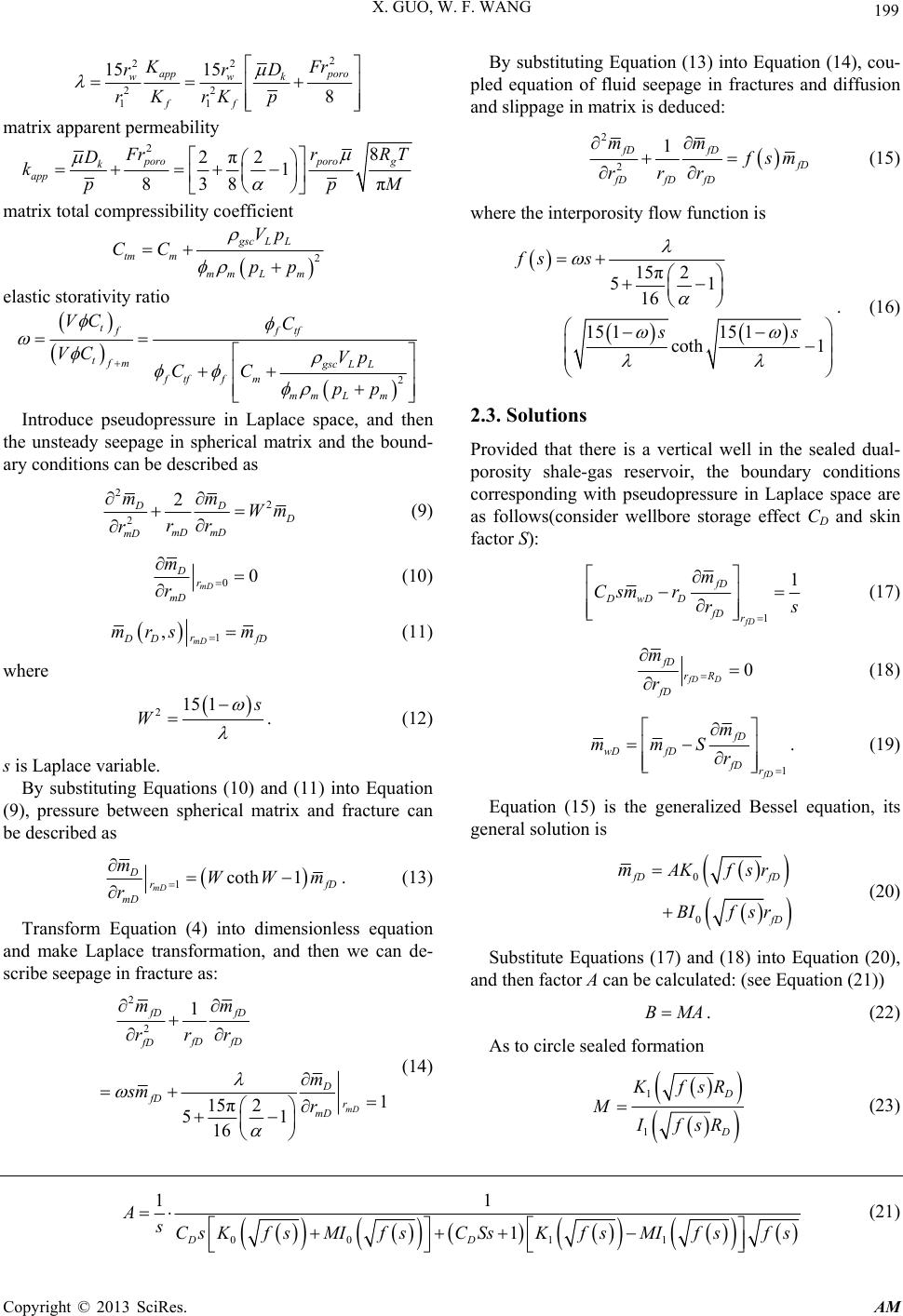 X. GUO, W. F. WANG Copyright © 2013 SciRes. AM 199 2 22 22 11 15 15 8 app poro wwk ff KF rrD Kp rrK r By substituting Equation (13) into Equation (14), cou- pled equation of fluid seepage in fractures and diffusion and slippage in matrix is deduced: matrix apparent permeability 28 2π21 838 π poroporo g k app F rr D kpp RT M 2 2 1 fD fD f D fD fD fD mm f sm rr r (15) matrix total compressibility coefficient where the interporosity flow function is 2 gsc LL tm m mm Lm Vp CC pp 15π2 51 16 15 1151 coth 1 fs s ss . (16) elastic storativity ratio 2 tfftf tfm gsc LL ftffm mm Lm VC C VC Vp CC pp 2.3. Solutions Introduce pseudopressure in Laplace space, and then the unsteady seepage in spherical matrix and the bound- ary conditions can be described as Provided that there is a vertical well in the sealed dual- porosity shale-gas reservoir, the boundary conditions corresponding with pseudopressure in Laplace space are as follows(consider wellbore storage effect CD and skin factor S): 2 2 2 2 DD D mD mD mD mm Wm rr r (9) 00 mD D r mD m r (10) 1 1 fD fD DwD D fD r m Csmr rs (17) 1 ,mD r D D mrs m fD (11) 0 fD D fD rR fD m r (18) where 2151 s W . (12) 1 fD fD wD fD fD r m mmS r . (19) s is Laplace variable. By substituting Equations (10) and (11) into Equation (9), pressure between spherical matrix and fracture can be described as Equation (15) is the generalized Bessel equation, its general solution is 0 0 fD fD f D A Kfsr BIfsr m (20) 1coth 1 mD D rf mD mWWm r D . (13) Transform Equation (4) into dimensionless equation and make Laplace transformation, and then we can de- scribe seepage in fracture as: Substitute Equations (17) and (18) into Equation (20), and then factor A can be calculated: (see Equation (21)) 2 2 1 1 15π2 51 16 mD fD fD fD fD fD D fD r mD mm rr r m sm r (14) BMA . (22) As to circle sealed formation 1 1 D D K fsR M IfsR (23) 00 11 11 1 DD AsCsKf sMIf sCSsKfsMIf sf s (21) 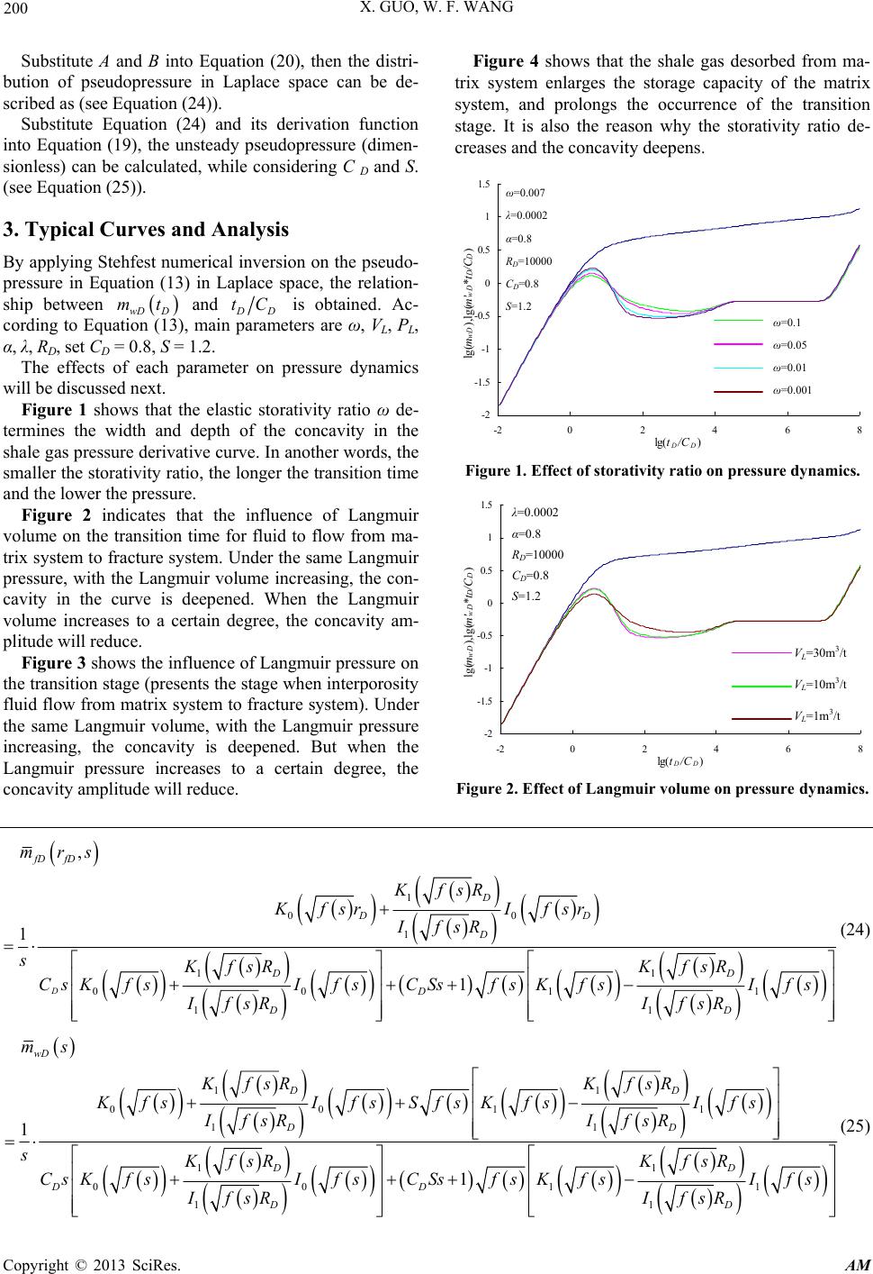 X. GUO, W. F. WANG 200 Substitute A and B into Equation (20), then the distri- bution of pseudopressure in Laplace space can be de- scribed as (see Equation (24)). Substitute Equation (24) and its derivation function into Equation (19), the unsteady pseudopressure (dimen- sionless) can be calculated, while considering C D and S. (see Equation (25)). 3. Typical Curves and Analysis By applying Stehfest numerical inversion on the pseudo- pressure in Equation (13) in Laplace space, the relation- ship between and wD D mt D D tC is obtained. Ac- cording to Equation (13), main parameters are ω, VL, PL, α, λ, RD, set CD = 0.8, S = 1.2. The effects of each parameter on pressure dynamics will be discussed next. Figure 1 shows that the elastic storativity ratio ω de- termines the width and depth of the concavity in the shale gas pressure derivative curve. In another words, the smaller the storativity ratio, the longer the transition time and the lower the pressure. Figure 2 indicates that the influence of Langmuir volume on the transition time for fluid to flow from ma- trix system to fracture system. Under the same Langmuir pressure, with the Langmuir volume increasing, the con- cavity in the curve is deepened. When the Langmuir volume increases to a certain degree, the concavity am- plitude will reduce. Figure 3 shows the influence of Langmuir pressure on the transition stage (presents the stage when interporosity fluid flow from matrix system to fracture system). Under the same Langmuir volume, with the Langmuir pressure increasing, the concavity is deepened. But when the Langmuir pressure increases to a certain degree, the concavity amplitude will reduce. Figure 4 shows that the shale gas desorbed from ma- trix system enlarges the storage capacity of the matrix system, and prolongs the occurrence of the transition stage. It is also the reason why the storativity ratio de- creases and the concavity deepens. -2 -1.5 -1 -0.5 0 0.5 1 1.5 -20246 lg(t D /C D ) lg(m wD ),lg (m 8 ' wD * t D / C D ) ω=0.1 ω=0.05 ω=0.01 ω=0.001 ω=0.007 λ =0.0002 α=0.8 R D =10000 C D =0.8 S=1.2 Figure 1. Effect of storativity ratio on pressure dynamics. -2 -1.5 -1 -0.5 0 0.5 1 1.5 -20 24 6 8 lg(t D /C D ) lg(m wD ),lg(m' wD *t D / C D ) V L =30m 3 /t V L =10m 3 /t V L =1m 3 /t λ =0.0002 α=0.8 R D =10000 C D =0.8 S=1.2 Figure 2. Effect of Langmuir volume on pressure dynamics. 1 00 1 1 1 00 1 1 1 , 1 1 D fD fD D DD D D D D D D mrs KfsR Kfsr Ifsr IfsR sKfsR KfsR CsKfsIfsCSsfs KfsIfs IfsR IfsR 1 (24) 1 1 0011 1 1 1 1 00 1 1 1 1 1 wD D D D D D D D D D D ms KfsRKf sR KfsIfsS fsKfsIfs IfsRIfsR sKfsR KfsR CsKfsIfsCSsfs KfsIfs IfsRIfsR 1 (25) Copyright © 2013 SciRes. AM  X. GUO, W. F. WANG 201 -2 -1.5 -1 -0.5 0 0.5 1 1.5 -20246 lg(t D /C D ) lg(m wD ),lg(m' wD *t D / 8 C D ) ω=0.007 λ =0.0002 α=0.8 R D =10000 C D =0.8 S=1.2 p L =3×10 7 Pa p L =1×10 7 Pa p L =1×10 6 Pa Figure 3. Effect of Langmuir pressure on pressure dyna- mics. -2 -1.5 -1 -0.5 0 0.5 1 1.5 -20 24 6 8 lg(t D /C D ) lg(m wD ),lg(m' wD *t D /C D ) λ =0.0002 α=0.8 R D =10000 C D =0.8 S =1.2 Without desorption With desoption Figure 4. Effect of gas desorption on pressure dynamics. Figure 5 describes the influence of the tangential momentum accommodation coefficient upon the pressure dynamics. With the tangential momentum accommoda- tion coefficient decreasing, the concavity in the typical curve deviates to right and becomes shallower, and the time for pressure wave to spread to the border reduces. Figure 6 shows that the interporosity flow coefficient determines the occurrence time of the transition stage too. With the interporosity flow coefficient increasing, the transition stage appears earlier, the concavity deviates to left and the interporosity flow gets more intense. Figure 7 reflects how boundary range influences the pressure dynamics. With the range getting narrower, the time for pressure wave to spread to the border reduces. When the pressure wave reaches the boundary, the pres- sure curve as well as its derivative curve upturns, finally the two curves are tangent into a straight line, whose slope turn to be 1. From all the figures, we can conclude that the pressure change of unsteady seepage in vertical wells in sealed shale-gas reservoir can be divided into three stages: Early wellbore storage; Transition stage: interporosity flow (from matrix sys- tem to fracture system) appears. Concavity of the -2 -1 0 1 2 3 4 -202468 lg(t D /C D ) lg(m wD ),lg(m 10 ' wD *t D / C D ) ω=0.007 λ =0.0002 R D =10000 C D =0.8 S=1.2 α=0.8 α=0.5 α=0.2 Figure 5. Effect of tangential momentum accommodation coefficient on pressure dynamics. -2 -1.5 -1 -0.5 0 0.5 1 1.5 -2 02468 lg(t D /C D ) lg(mwD),lg(m'wD*tD/ C D) ω=0.007 α=0.8 R D =10000 C D =0.8 S=1.2 λ =0.01 λ =0.001 λ =0.0001 Figure 6. Effect of interporosity flow coefficient on pres- sure dynamics. -2 -1 0 1 2 3 4 -202468 lg(t D /C D ) lg(m wD ),lg(m 10 ' wD *t D / C D ) ω=0.007 λ =0.0002 α=0.8 C D =0.8 S=1.2 R D =10000 R D =7000 R D =4000 Figure 7. Effect of boundary on pressure dynamic s. curve appears in this stage too; The radial flow of dual porosity system: this stage presents the homogeneous characteristics of forma- tion. Pressure derivative curve shows a horizontal line, whose value is 0.5. 4. Conclusions 1) According to the characteristics of shale gas in ad- sorption-desorption, diffusion, slippage and seepage dur- ing accumulation, migration and production, a mathe- Copyright © 2013 SciRes. AM  X. GUO, W. F. WANG 202 matical model of unsteady seepage in dual-porosity sealed shale-gas reservoir was built while considering Knudsen diffusion, slip-flow effect and Langmuir desorption ef- fect. By solving the model utilizing the Stehfest numeri- cal inversion and computer programming in Laplace space, several typical curves of bottomhole pressure were obtained. 2) In the sealed shale-gas reservoir, the stage when flow in fracture system exists only is extremely transient, the transition stage appears immediately after the well- bore storage stage. So in fracture system, radial flow doesn’t appear. The pressure dynamics of unsteady seep- age appear only in storage stage, the radial flow stage, and the stage when the pressure is unsteady. 3) The typical curves of bottomhole pressure are pre- sented to discuss the influences of several sensitive pa- rameters upon pressure behavior. These sensitive pa- rameters include elastic storativity ratio, Langmuir vol- ume, Langmuir pressure, adsorption-desorption, tangen- tial momentum accommodation coefficient, interporosity flow coefficient, and boundary range. The smaller the storativity ratio, the longer the transition stage. The changes of Langmuir volume and Langmuir pressure, as well as desorption and adsorption mechanisms are the internal causes of the storativity ratio change. The tan- gential momentum accommodation coefficient describes smoothness of the pores’ inner face, With the tangential momentum accommodation coefficient decreasing, the concavity of typical curves deviates right and becomes shallower, and the time for pressure wave to spread to the border reduces; The interporosity flow coefficient deter- mines the occurrence time of the transition stage. With the interporosity flow coefficient increasing, the transi- tion stage appears earlier, the concavity deviates to left and the interporosity flow gets more intense; with the boundary range getting narrower, the time for pressure wave to spread the border reduces. REFERENCES [1] Z. L. Ping and P. R. Fang, “Accumulation and Transfor- mation of Shale Gas Reservoir,” China Petroleum Ex- ploration, Vol. 3, 2009, pp. 20-23. [2] D. Y. Gang, W. M. Qiang and L. J. Qiu, “Shale Gas Seepage Mechanism and Fractured Wells Production Evaluation,” Journal of Chongqing University, Vol. 34, No. 4, 2011, pp. 62-66. [3] G. S. Sheng, Y. X. He and L. H. Xun, “Impact of Slip- page on Shale Gas Well Productivity,” Natural Gas Tndustry, Vol. 31, No. 4, 2011, pp. 55-58. [4] F. Javadpour, “Nanopores and Apparent Permeability of Gas Flow in Mudrocks (Shales and Siltstone),” Journal of Canadian Petroleum Technology, Vol. 48, No. 8, 2009, pp. 16-21. doi:10.2118/09-08-16-DA [5] V. Shabro, C. Torres-Verdín and F. Javadpour, “Numeri- cal Simulation of Shale-Gas Production: From Pore-Scale Modeling of Slip-Flow, Knudsen Diffusion, and Lang- muir Desorption to Reservoir Modeling of Compressible Fluid,” SPE North American Unconventional Gas Con- ference and Exhibition in The Woodlands, Texas, 14-16 June 2011, pp. 2-4. doi:10.2118/144355-MS [6] D. Tzoulaki, L. Heinke and H. Lim. “Assessing Surface Permeabilities from Transient Guest Profiles in Nano- porous Host Materials,” Angewandte Chemie Interna- tional Edition, Vol. 48, No. 19, 2009, pp. 3525-3528. doi:10.1002/anie.200804785 [7] M. H. M. Hassan and J. D. Way, “Gas Transport in A Microporous Silica Membrane,” SPE Abu Dhabi Interna- tional Petroleum Exhibition and Conference, Abu Dhabi, 13-16 October 1996, pp. 2-3. doi:10.2118/36226-MS [8] E. Ozkan and R. Raghavan, “Modeling of Fluid Transfer From Shale Matrix to Fracture Network,” SPE Annual Technical Conference and Exhibition, Florence, 19-22 September 2010, pp. 10-13. doi:10.2118/134830-MS [9] C. M. Freeman, G. Moridis, D. Ilk and T. A. Blasingame. “A Numerical Study of Performance for Tight Gas and Shale Gas Reservoir Systems,” SPE Annual Technical Conference and Exhibition, New Orleans, 4-7 October 2009, pp. 9-12. doi:10.2118/124961-MS [10] G. J. Moridis, T. A. Blasingame and C. M. Freeman, “Analysis of Mechanisms of Flow in Fractured Tight-Gas and Shale-Gas Reservoirs,” SPE Latin American & Car- ibbean Petroleum Engineering Conference Lima, Peru, 1-3 December 2010, pp. 20-22. doi:10.2118/139250-MS [11] H. Stehfest, “Algorithm 368 Numerical Inversion of Laplace Transforms,” Communications of ACM, Vol.13, No.1, 1970, pp. 47-49. doi:10.1145/361953.361969 [12] F. Javadpour, D. Fisher and M. Unsworth, “Nanoscale Gas Flow in Shale Gas Sediments,” Canadian Petroleum Technology, Vol. 46, No. 10, 2007, pp. 55-61. [13] S. Roy, R. Raju and F. H. Chuang, “Modelling Gas Flow through Microchannels and Nanopores,” Journal of Ap- plied Physics, Vol. 93, No. 8, 2003, pp. 4870-4879. doi:10.1063/1.1559936 [14] P. G. Brwon, A. Dinnado and K. G. Cheng, “The Flow of Gas in Pipes at Low Pressures,” Journal of Applied Phys- ics, Vol. 17, No. 10, 1946, pp. 802-813. doi:10.1063/1.1707647 [15] A. E. Schrodinger, “The Physics of Flow through Porous Media,” University of Toronto Press, Toronto, 1974. Copyright © 2013 SciRes. AM  X. GUO, W. F. WANG 203 Nomenclature VE: total volume of gas adsorbed of per unit volume of the reservoir in equilibrium at pressure P, m3/t; VL: Langmuir volume, the maximum sorption capacity of the shale, m3/t; PL: Langmuir pressure, at which the total gas volume adsorbed, VE, is equal to 50% of the Langmuir volume, Pa; P: pressure, Pa; Pi: initial pressure, Pa; p: average pressure, Pa; ω: dimensionless storativity ratio; λ: dimensionless interporosity flow coefficient; K: absolute permeability, m2; M: molar mass, kg/mol; Z: gas compressibility, fraction; Rg: universal gas constant, 8.314Pa·m3/ (mol·K); T: temperature, K; ρ: density, kg/m3 μ: viscosity, Pa·s; : average viscosity Pa·s; φ: porosity, fraction; C: gas compressibility, Pa−1; α: tangential momentum accommodation coefficient, depending on the smoothness of the pores’ inner face, gas type, temperature and pressure, fraction (0 ~ 1); r: radial distance in spherical coordinates, m; rporo: matrix system pore radius, m; r1: spherical matrix block radius, m; rw: gas well radius, m; R: gas reservoir boundary, m; S: skin coefficient, fraction; CD: dimensionless wellbore storage factor; m: pseudopressure; mD: dimensionless pseudopressure; D m: dimensionless pseudopressure in Laplace space; wD m: dimensionless bottom hole pseudopressure in Laplace space; s: Laplace transform variable; f(s): interporosity flow function; Iυ: υ order of first species modified Bessel function, Kυ: υ order of second species modified Bessel function, υ = 0.1. Copyright © 2013 SciRes. AM |