

Paper Menu >>
Journal Menu >>
 Circuits and Systems, 2013, 4, 29-33 http://dx.doi.org/10.4236/cs.2013.41006 Published Online January 2013 (http://www.scirp.org/journal/cs) Universal Current-Mode Biquad Filter Using a VDTA Dinesh Prasad1*, Data Ram Bhaskar1, Mayank Srivastava2 1Department of Electronics and Communication Engineering, Faculty of Engineering and Technology, Jamia Millia Islamia, New Delhi, India 2D/O Electronics and Communication Engineering, Amity School of Engineering and Technology, Amity University, Noida, India Email: *[email protected], dbhaskar@jmi.ac.in, [email protected] Received October 9, 2012; revised November 9, 2012; accepted November 16, 2012 ABSTRACT This paper presents a new current-mode single input multi output (SIMO) type biquad employing one voltage differ- encing transconductance amplifier (VDTA), two grounded capacitors and a single grounded resistor. The configuration realizes all basic filter functions (i.e. Low Pass (LP), High Pass (HP), Band Pass (BP), Notch (BR) and All Pass (AP)). The natural frequency (ω0) and bandwidth (BW) are independently tunable. The workability of proposed configuration has been verified using SPICE simulation with TSMC CMOS 0.18 μm process parameters. Keywords: Current Mode Filter; Voltage Differencing Transconductance Amplifier 1. Introduction Active filters are important basic building blocks, which are frequently employed in electrical engineering appli- cations. The current-mode approach [1] in designing ac- tive filters has become more popular due to its advanta- geous features such as larger dynamic range and wider bandwidth as compared to voltage-mode counterparts (particularly for the high frequency operations), simpler filtering configurations and lower power consumption. During the past few years, active filters using different current-mode/voltage-mode building blocks have been employed in which VDTA, recently introduced in [2], appears to be a useful active building block for an easy CMOS implementation of current-mode signal process- ing/signal generation [3-5]. Various SIMO-type active filters using different active elements are available in the literature see [6-13] and the references cited therein. In references [6-9], SIMO-type filter configurations employing 2/4 resistors and 2/3 ca- pacitors have been presented. These proposed filter struc- tures do not realize all the five filter responses. The con- figurations presented in [10] and [11] although use one resistor and two capacitors but fail to realize all the basic filter functions. Although the biquads proposed in [12] and [13] realize all the five filter functions but they use two capacitors along with 2/3 resistors. Therefore, the purpose of this communication is to propose a new SIMO-type current-mode universal biquad filter em- ploying one VDTA, two grounded capacitors and a sin- gle grounded resistor, which realizes all the basic filter functions i.e. LP, HP, BP, BR and AP. The natural fre- quency ω0 and BW are independently tunable. The pro- posed circuit also offers low active and passive sensitivi- ties. The workability of proposed configuration has been verified using SPICE simulation with TSMC CMOS 0.18 μm process parameters. 2. The Proposed New Configurations The symbolic notation of the VDTA is shown in Figure 1, where VP and VN are input terminals and Z, X+ and X− are output terminals. All terminals of VDTA exhibit high impedance values [2]. The VDTA can be described by the following set of equations: 11 2 2 0 00 00 P N mm V Z mV X mZ X gg V I IgV gV I (1) The proposed circuit configuration is shown in Figure 2. A routine circuit analysis of Figure 2 yields the fol- lowing filter transfer functions: 12 1 1 mm o LP in g g I Ts (2) I Ds 1 1 2 2 m o BP in g sC I Ts I Ds (3) *Corresponding author. C opyright © 2013 SciRes. CS 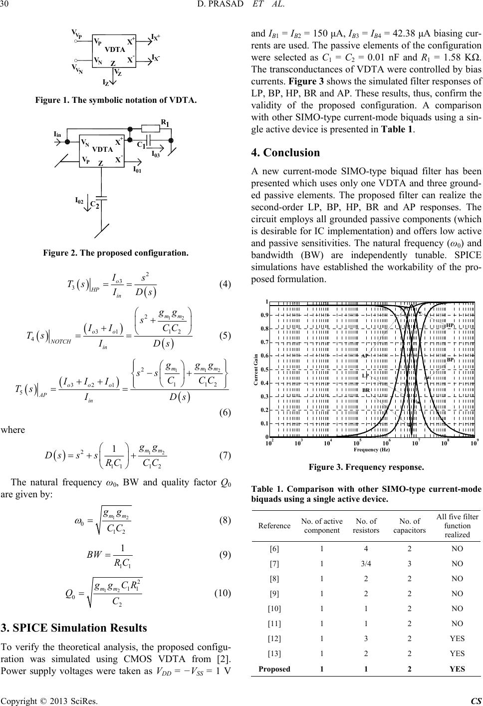 D. PRASAD ET AL. 30 V PVD V NX Z X TA IZ V P V V N V + - IX+ IX- V Z Figure 1. The symbolic notation of VDTA. R1 C1 VX Z X P VDTA VN+ - I01 Iin C2 I02 I03 Figure 2. The proposed configuration. 2 3o in I 3HP s Ts I Ds (4) 12 2 12 mm gg sCC IDs 31 4 oo NOTCH in II Ts (5) 112 11 2 mmm ggg CCC s 2 321 5 ooo AP in ss III Ts ID (6) where 12 11 12 mm 21 g g CC Dsss RC (7) The natural frequency ω0, BW and quality factor Q0 are given by: 12 0 12 mm g g CC (8) 11 1 BW RC (9) 12 2 11 2 mm 0 g gCR C Q (10) 3. SPICE Simulation Results To verify the theoretical analysis, the proposed configu- ration was simulated using CMOS VDTA from [2]. Power supply voltages were taken as VDD = −VSS = 1 V and IB1 = IB2 = 150 μA, IB3 = IB4 = 42.38 μA biasing cur- rents are used. The passive elements of the configuration were selected as C1 = C2 = 0.01 nF and R1 = 1.58 KΩ. The transconductances of VDTA were controlled by bias currents. Figure 3 shows the simulated filter responses of LP, BP, HP, BR and AP. These results, thus, confirm the validity of the proposed configuration. A comparison with other SIMO-type current-mode biquads using a sin- gle active device is presented in Table 1. 4. Conclusion A new current-mode SIMO-type biquad filter has been presented which uses only one VDTA and three ground- ed passive elements. The proposed filter can realize the second-order LP, BP, HP, BR and AP responses. The circuit employs all grounded passive components (which is desirable for IC implementation) and offers low active and passive sensitivities. The natural frequency (ω0) and bandwidth (BW) are independently tunable. SPICE simulations have established the workability of the pro- posed formulation. 1 10 2 10 3 10 4 10 5 10 6 10 7 10 8 10 9 0 0.1 0.2 0.3 0.4 0.5 0.6 0.7 0.8 0.9 HP Freque ncy (Hz) Current Gain AP BP LP BR Figure 3. Frequency response. Table 1. Comparison with other SIMO-type current-mode biquads using a single active devic e. Reference No. of active component No. of resistors No. of capacitors All five filter function realized [6] 1 4 2 NO [7] 1 3/4 3 NO [8] 1 2 2 NO [9] 1 2 2 NO [10] 1 1 2 NO [11] 1 1 2 NO [12] 1 3 2 YES [13] 1 2 2 YES Proposed1 1 2 YES Copyright © 2013 SciRes. CS  D. PRASAD ET AL. Copyright © 2013 SciRes. CS 31 4. Acknowledgements This work was performed at the Advanced Analog Signal Processing Laboratory of the Department of Electronics and Communication Engineering, F/o Engineering and Technology, Jamia Millia Islamia, Jamia Nagar, New Delhi-110025, India. REFERENCES [1] C. Toumazau, F. J. Lidgey and D. G. Haigh, “Analogue IC Design: The Current-Mode Approach,” Peter Peregrinus Limited, London, 1990. [2] D. Biolek, R. Senani, V. Biolkova and Z. Kolka, “Active Elements for Analog Signal Processing, Classification, Review and New Proposals,” Radioengineering, Vol. 17, No. 4, 2008, pp. 15-32. [3] A. Yesil, F. Kacar and H. Kuntman, “New Simple CMOS Realization of Voltage Differencing Transconductance Amplifier and Its RF Filter Application,” Radioengineer- ing, Vol. 20, No. 3, 2011, pp. 632-637. [4] D. Prasad and D. R. Bhaskar, “Electronically-Controllable Explicit Current Output Sinusoidal Oscillator Employing Single VDTA,” ISRN Electronics, Vol. 2012, 2012, Arti- cle ID: 382560. doi:10.5402/2012/382560 [5] J. Satansup, T. Pukkalanun and W. Tangsrirat, “Electroni- cally Tunable Single-Input Five-Output Voltage-Mode Universal Filter Using VDTAs and Grounded Passive Elements,” Circuits, Systems, and Signal Processing, 2012 (online). doi:10.1007/s00034-012-9492-0 [6] A. Fabre and J. L. Houle, “Voltage-Mode and Current- Mode Sallen-Key Implementations Based on Translinear Conveyors,” IEEE Proceedings-G: Circuits, Devices and Systems, Vol.139, No.7, 1992, pp. 491-497. [7] C. M. Chang, C. C. Chien and H. Y. Wang, “Universal Active Current Filters Using Single Second Generation Current Conveyor,” Electronics Letters, Vol. 29, No. 13, 1993, pp. 1159-1160. doi:10.1049/el:19930775 [8] E. Yuce, B. Metin and O. Cicekoglu, “Current-Mode Bi- quadratic Filters Using Single CCIII and Minimum Num- ber of Passive Elements,” Frequenz: Journal of RF-En- gineering and Telecommunications, Vol. 58, No. 9-10, 2004, pp. 225-227. [9] B. Chaturvedi and S. Maheshwari, “Current Mode Biquad Filter with Minimum Component Count,” Journal of Ac- tive and Passive Electronic Components, Vol. 2011, 2011, Article ID: 391642. doi:10.1155/2011/391642 [10] D. Biolek, V. Biolkova and Z. Kolka, “Current-Mode Biquad Employing Single CDTA,” Indian Journla of Pure and Applied Physics, Vol. 47, No. 7, 2009, pp. 535- 537. [11] W. Tangsrirat, “Novel Current-Mode and Voltage-Mode Universal Biquad Filters Using Single CFTA,” Indian Journal of Engineering and Material Science, Vol. 17, 2010, pp. 99-104. [12] C. N. Lee and C. M. Chang, “Single FDCCII-Based Mixed-Mode Biquad Filter with Eight Outputs,” AEU: International Journal of Electronics and Communications, Vol. 63, No. 9, 2009, pp. 736-742. doi:10.1016/j.aeue.2008.06.015 [13] D. Prasad, D. R. Bhaskar and A. K. Singh, “Universal Current-Mode Biquad Filter Using Dual Output Current Differencing Transconductance Amplifier,” AEU: Inter- national Journal of Electronics and Communications, Vol. 63, No. 6, 2009, pp. 497-501. doi:10.1016/j.aeue.2008.02.012 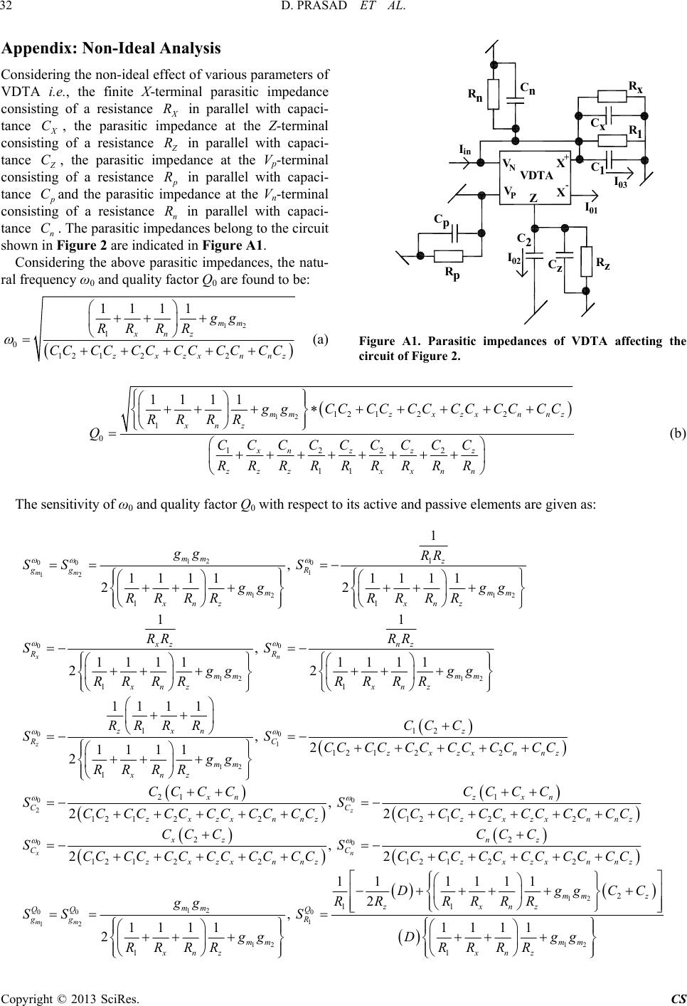 D. PRASAD ET AL. 32 Appendix: Non-Ideal Analysis Considering the non-ideal effect of various parameters of VDTA i.e., the finite X-terminal parasitic impedance consisting of a resistance X in parallel with capaci- tance X, the parasitic impedance at the Z-terminal consisting of a resistance R C Z R in parallel with capaci- tance Z C, the parasitic impedance at the Vp-terminal consisting of a resistance p R in parallel with capaci- tance p C R C and the parasitic impedance at the Vn-terminal consisting of a resistance n in parallel with capaci- tance n. The parasitic impedances belong to the circuit shown in Figure 2 are indicated in Figure A1. Considering the above parasitic impedances, the natu- ral frequency ω0 and quality factor Q0 are found to be: 12 2 mm 1 0 12 12 1111 xn z z xzx RR RR CC CC CCCC nnz gg CC CC R1 C1 VX Z X P VDTA VN (a) + - I01 Iin Rx Cx RnCn C2 I02 I03 CzRz Rp Cp Figure A1. Parasitic impedances of VDTA affecting the circuit of Figure 2. 12 12 122 1222 11 11 mmzx zxnnz z xn zzz zzz xxnn 1 0 11 xn g g CCCCCCCCCCCC R CC C CCCCCC RRRRRRRRR RR R Q (b) The sensitivity of ω0 and quality factor Q0 with respect to its active and passive elements are given as: 12 00 0 1 12 12 12 0 0 12 1 1 11 11 1 , 1111 1111 22 11 , 1111 1111 22 mm x n mm z ggR mm mm xnz xnz xz nz RR mm m xnz xnz gg RR SS S gg gg RR RRRR RR RR RR SS gg gg RR RRRR RR 2 2 11 11 m nnz xn RR RRCC C CC C C C 0 0 1 12 0 0 2 112 12 12 1 21 1 12 12212 1 , 2 1111 2 , 22 z z zx nz RC zxzx mm xnz xn z C C zxzxnnzz SS CC CC CC CC C gg RR RR CC CCCC SS CC CC CC CCCC CCCC CC 0 0 22 2 2 12 12212 122 , 22 x n xzx nnz xz nz C C zxzxnnzzxzxnnz CC CC CCCC CC CCC C SS CC CC CC CC CC CCCC CCCC CC CC CC 12 00 0 1 12 12 11 1 11 111 2 , 1111 2 mm zx n mm QQ Q ggR mm xnz D RR RRR gg SS S gg RR RR 12 12 1 1 1111 mm z mm xnz gg R Dg RR RR 2z C C g Copyright © 2013 SciRes. CS 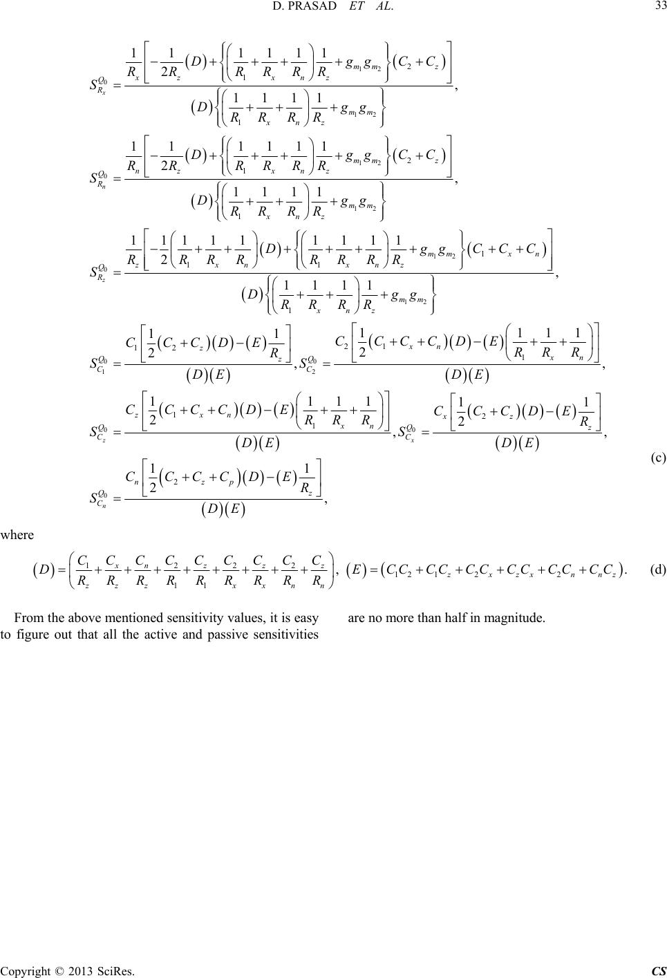 D. PRASAD ET AL. 33 12 0 12 12 0 12 2 1 1 2 1 1 11 1111 2, 1111 11 1111 2 1111 x n mm z xz xnz Q R mm xnz mm z nz xnz Q R mm xnz DggCC RR RRRR S Dgg RR RR DggCC RR RRRR S Dgg RR RR 12 0 12 00 12 1 11 1 21 12 1 , 11111 1111 2 1111 11 11 2 2, z mm x zxn xnz Q R mm xnz xn z z QQ CC Dgg RRRRRRRR S Dgg RR RR CCCCDE CCCDE R SS DE , 11 n xn CCC RR R 0 0 0 12 1 2 11 11 22 11 2, z x n zxn xz xn Q Q C C nzp z Q C DE CCCCDE CCC RR R SS DE DE CCCCDE R SDE , 11 ,, z DE R (c) where 1 222 12 12 11 xn zzz zx zx zzz xxnn CC C CCCCCC DECC CC CC CC C RRRRRRRRR 2 ,. nnz CC C (d) From the above mentioned sensitivity values, it is easy to figure out that all the active and passive sensitivities are no more than half in magnitude. Copyright © 2013 SciRes. CS |