

Paper Menu >>
Journal Menu >>
 Circuits and Systems, 2013, 4, 16-19 http://dx.doi.org/10.4236/cs.2013.41004 Published Online January 2013 (http://www.scirp.org/journal/cs) EMTP Induction Motor Model from Modal Measurements for Inverter Surge Analysis Asha Shendge, Naoto Nagaoka Department of Electrical and Electronics Engineering, Doshisha University, Kyoto, Japan Email: [email protected], nnagaoka@mail.doshisha.ac.jp Received September 14, 2012; revised December 4, 2012; accepted December 11, 2012 ABSTRACT The over-voltage phenomenon is usually described using the traveling wave and reflection phenomena in variable speed drive system. A voltage pulse, initiated at the inverter, being reflected at the motor terminals due to a mismatch between the surge impedance of the motor and the cable. In this paper, resistance, inductance and capacitance of the cable and the motor windings are obtained experimentally by modal measurements and suitable models are developed to match the experimental results by considering resonance in the motor winding. This paper emphasize on Induction motor model using the theory of natural modes of propagation. The developed model validity is investigated for inverter surge application. Keywords: Induction Motor; Modal Measurements; Inverter Surge; EMTP 1. Introduction An induction motor (IM) is an asynchronous AC ma- chine that consists of a stator and a rotor. An induction motor is widely used because of the rugged construction and moderate cost. Recently, the variable speed drives produced mostly consist of brushless motors and power converters. In many cases the squirrel cage induction motor is used and it is controlled by a voltage fed PWM inverter. The motor is controlled via the PWM inverter by keeping the amplitude and frequency of the reference (sinusoidal) signals constant according to the desired output speed. Thus, maintaining constant magnetic flux in the motor. For micro-surge due to reflection and re- fraction at motor terminal voltage peaks are developed. It is necessary to have accurate induction motor model in consideration of frequency dependent effect as motor resistance, inductance and capacitance are frequency dependent due to transient phenomena. There are several studies carried out by different au- thors to simulate peak voltages at motor terminals due to inverter surge [1-5]. In this paper three phase induction motor model is developed based on natural mode meas- urements in steady state. The analytical calculations are carried out using theory of resonance in motor winding. The modal to phase transformation are implemented us- ing a computational tool such as Maple, which provides template, a convenient method to analyze matrix calcula- tions. Thus suitable induction motor model is developed for Electro-Magnetic Transient Program (EMTP). Motor peak voltage that is surge voltage is proposed as input step waveform. The validity of model is checked by ac- tual transient measurement of inverter surge phenomena. It is observed the model gives good agreement results for inverter surge application. 2. Experimental Set Up A 3 phase, 2.2 Kw, 50 Hz, 200 Volts, 9.2 Amp, 1430 RPM squirrel cage induction motor is used for analysis. Motor stator is connected in Delta connection. Motor is squirrel cage means rotor winding is shorted. Steady state measurements are carried out on de-energized condition for mode-0, mode-1 and mode-2. The current distribution for all propagation modes is as shown in Figure 1. An impedance analyzer is used as input source (Agilent model 4294A 40 Hz - 110 MHz). Before measurements calibration is done according to the manufacture’s manual. 2.1. Measured Results Figures 2(a)-(c) are represents mode-0, mode-1 and (a) mode-0 (b) mode-1 (c) mode-2 Figure 1. Current distribution of three propagation modes. C opyright © 2013 SciRes. CS 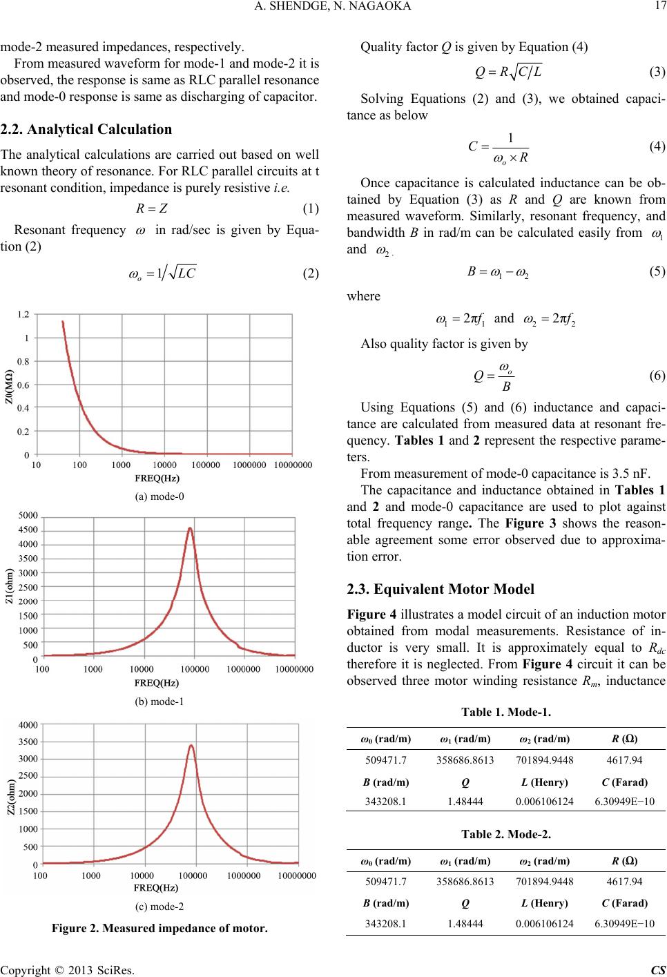 A. SHENDGE, N. NAGAOKA 17 mode-2 measured impedances, respectively. From measured waveform for mode-1 and mode-2 it is observed, the response is same as RLC parallel resonance and mode-0 response is same as discharging of capacitor. 2.2. Analytical Calculation The analytical calculations are carried out based on well known theory of resonance. For RLC parallel circuits at t resonant condition, impedance is purely resistive i.e. RZ (1) Resonant frequency in rad/sec is given by Equa- tion (2) 1 oLC (2) (a) mode-0 (b) mode-1 (c) mode-2 Figure 2. Measured impedance of motor. Quality factor Q is given by Equation (4) QRCL (3) Solving Equations (2) and (3), we obtained capaci- tance as below 1 o CR 1 (4) Once capacitance is calculated inductance can be ob- tained by Equation (3) as R and Q are known from measured waveform. Similarly, resonant frequency, and bandwidth B in rad/m can be calculated easily from and 2 . 12 B (5) 11 2π where f and 22 2π f Also quality factor is given by o QB (6) Using Equations (5) and (6) inductance and capaci- tance are calculated from measured data at resonant fre- quency. Tables 1 and 2 represent the respective parame- ters. From measurement of mode-0 capacitance is 3.5 nF. The capacitance and inductance obtained in Tables 1 and 2 and mode-0 capacitance are used to plot against total frequency range. The Figure 3 shows the reason- able agreement some error observed due to approxima- tion error. 2.3. Equivalent Motor Model Figure 4 illustrates a model circuit of an induction motor obtained from modal measurements. Resistance of in- ductor is very small. It is approximately equal to Rdc therefore it is neglected. From Figure 4 circuit it can be observed three motor winding resistance Rm, inductance Table 1. Mode-1. ω0 (rad/m) ω1 (rad/m) ω2 (rad/m) R (Ω) 509471.7 358686.8613 701894.9448 4617.94 B (rad/m) Q L (Henry) C (Farad) 343208.1 1.48444 0.006106124 6.30949E−10 Table 2. Mode-2. ω0 (rad/m) ω1 (rad/m) ω2 (rad/m) R (Ω) 509471.7 358686.8613 701894.9448 4617.94 B (rad/m) Q L (Henry) C (Farad) 343208.1 1.48444 0.006106124 6.30949E−10 Copyright © 2013 SciRes. CS 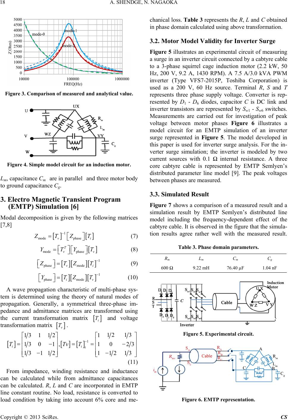 A. SHENDGE, N. NAGAOKA 18 Figure 3. Comparison of measured and analytical value. Figure 4. Simple model circuit for an induction motor. Lm, capacitance Cm are in parallel and three motor body to ground capacitance Cg. 3. Electro Magnetic Transient Program (EMTP) Simulation [6] Modal decomposition is given by the following matrices [7,8] mode 1 phasevi Z TZ T (7) mode T YTphasevv YT 1 modevi (8) phase Z TZ T 1 modeiv ZT (9) phase YT (10) A wave propagation characteristic of multi-phase sys- tem is determined using the theory of natural modes of propagation. Generally, a symmetrical three-phase im- pedance and admittance matrices are transformed using the current transformation matrix i T and voltage transformation matrix v T. 1 131 121 1301 ,1 131 121 ii t TTvT 12 13 0 23 12 13 (11) From impedance, winding resistance and inductance can be calculated while from admittance capacitances can be calculated. R, L and C are incorporated in EMTP line constant routine. No load, resistance is converted to load condition by taking into account 6% core and me- chanical loss. Table 3 represents the R, L and C obtained in phase domain calculated using above transformation. 3.2. Motor Model Validity for Inverter Surge Figure 5 illustrates an experimental circuit of measuring a surge in an inverter circuit connected by a cabtyre cable to a 3-phase squirrel cage induction motor (2.2 kW, 50 Hz, 200 V, 9.2 A, 1430 RPM). A 7.5 A/3.0 kVA PWM inverter (Type VFS7-2015P, Toshiba Corporation) is used as a 200 V, 60 Hz source. Terminal R, S and T represents three phase supply voltage. Converter is rep- resented by D1 - D6 diodes, capacitor C is DC link and inverter transistors are represented by Sw1 - Sw6 switches. Measurements are carried out for investigation of peak voltage between motor phases Figure 6 illustrates a model circuit for an EMTP simulation of an inverter surge represented in Figure 5. The model developed in this paper is used for inverter surge analysis. For the in- verter surge simulation; the inverter is modeled by two current sources with 0.1 Ω internal resistance. A three core cabtyre cable is represented by EMTP Semlyen’s distributed parameter line model [9]. The peak voltages between phases are measured. 3.3. Simulated Result Figure 7 shows a comparison of a measured result and a simulation result by EMTP Semlyen’s distributed line model including the frequency-dependent effect of the cabtyre cable. It is observed in the figure that the simula- tion results agree rather well with the measured result. Table 3. Phase domain parameters. Rm L m C m C g 600 Ω 9.22 mH 76.40 µF 1.04 nF Figure 5. Experimental circuit. Figure 6. EMTP representation. Copyright © 2013 SciRes. CS 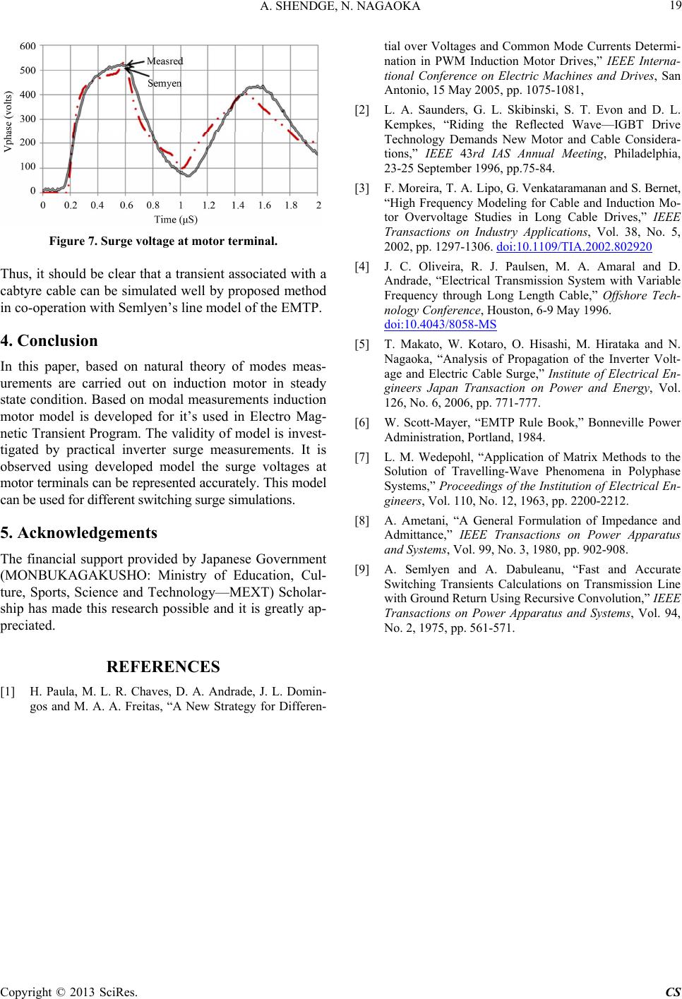 A. SHENDGE, N. NAGAOKA Copyright © 2013 SciRes. CS 19 Figure 7. Surge voltage at motor terminal. Thus, it should be clear that a transient associated with a cabtyre cable can be simulated well by proposed method in co-operation with Semlyen’s line model of the EMTP. 4. Conclusion In this paper, based on natural theory of modes meas- urements are carried out on induction motor in steady state condition. Based on modal measurements induction motor model is developed for it’s used in Electro Mag- netic Transient Program. The validity of model is invest- tigated by practical inverter surge measurements. It is observed using developed model the surge voltages at motor terminals can be represented accurately. This model can be used for different switching surge simulations. 5. Acknowledgements The financial support provided by Japanese Government (MONBUKAGAKUSHO: Ministry of Education, Cul- ture, Sports, Science and Technology—MEXT) Scholar- ship has made this research possible and it is greatly ap- preciated. REFERENCES [1] H. Paula, M. L. R. Chaves, D. A. Andrade, J. L. Domin- gos and M. A. A. Freitas, “A New Strategy for Differen- tial over Voltages and Common Mode Currents Determi- nation in PWM Induction Motor Drives,” IEEE Interna- tional Conference on Electric Machines and Drives, San Antonio, 15 May 2005, pp. 1075-1081, [2] L. A. Saunders, G. L. Skibinski, S. T. Evon and D. L. Kempkes, “Riding the Reflected Wave—IGBT Drive Technology Demands New Motor and Cable Considera- tions,” IEEE 43rd IAS Annual Meeting, Philadelphia, 23-25 September 1996, pp.75-84. [3] F. Moreira, T. A. Lipo, G. Venkataramanan and S. Bernet, “High Frequency Modeling for Cable and Induction Mo- tor Overvoltage Studies in Long Cable Drives,” IEEE Transactions on Industry Applications, Vol. 38, No. 5, 2002, pp. 1297-1306. doi:10.1109/TIA.2002.802920 [4] J. C. Oliveira, R. J. Paulsen, M. A. Amaral and D. Andrade, “Electrical Transmission System with Variable Frequency through Long Length Cable,” Offshore Tech- nology Conference, Houston, 6-9 May 1996. doi:10.4043/8058-MS [5] T. Makato, W. Kotaro, O. Hisashi, M. Hirataka and N. Nagaoka, “Analysis of Propagation of the Inverter Volt- age and Electric Cable Surge,” Institute of Electrical En- gineers Japan Transaction on Power and Energy, Vol. 126, No. 6, 2006, pp. 771-777. [6] W. Scott-Mayer, “EMTP Rule Book,” Bonneville Power Administration, Portland, 1984. [7] L. M. Wedepohl, “Application of Matrix Methods to the Solution of Travelling-Wave Phenomena in Polyphase Systems,” Proceedings of the Institution of Electrical En- gineers, Vol. 110, No. 12, 1963, pp. 2200-2212. [8] A. Ametani, “A General Formulation of Impedance and Admittance,” IEEE Transactions on Power Apparatus and Systems, Vol. 99, No. 3, 1980, pp. 902-908. [9] A. Semlyen and A. Dabuleanu, “Fast and Accurate Switching Transients Calculations on Transmission Line with Ground Return Using Recursive Convolution,” IEEE Transactions on Power Apparatus and Systems, Vol. 94, No. 2, 1975, pp. 561-571. |