

Paper Menu >>
Journal Menu >>
 Open Journal of Applied Sciences, 2013, 3, 75-78 Published Online March 2013 (http://www.scirp.org/journal/ojapps) Copyright © 2013 SciRes. OJAppS Modeling Camera Image Formation Using a Feedforward Neural Network Yongtae Do Electronic Control Major, Division of Electronic & Electrical Engineering, Daegu University, 712-714, South Korea Email: [email protected] Received 2012 ABSTRACT One fundamental problem in computer vision and image processing is modeling the image formation of a camera, i.e., mapping a point in three-dimensional space to its projected position on the camera’s image plane. If the relationship between the space and the image plane is assumed to be linear, the relationship can be expressed in terms of a transfor- mation matrix and the matrix is often identified by regression. In this paper, we show that the space-to-image relation- ship in a camera can be modeled by a simple neural network. Unlike most other cases employing neural networks, the structure of the network is optimized so as for each link between neurons to have a physical meaning. This makes it possible to effectively initialize link weights and quickly train the network. Keywords: Ca mera Mod el; Camera Calibra tion; Image Formation; Neural Netwo rk 1. Introduction A camera can be considered as a device that records ob- jects in three-dimensional (3D) space in the form of their two-dimensional (2D) images. In some technical fields where the use of a camera is required, such as computer vision and image processing, accurate and efficient mod- eling of the camera’s image formation process is a basic problem that must be solved. For a camera installed in a certain task, the image for- mation in the camera is characterized with the internal and external parameters of the camera [1]. The internal parameters include focal length, optical image center, and lens distortion coefficients, whereas the external pa- rameters are those for specifying the geometric position and orientation of the camera. The camera model para- meter determination process is called camera calibration [2]. Once a camera is calibrated, it is possible to compu- tationally relate objects in 3D world and their projections on the ca mera’s image plane. Camera modeling and calibration have received great attention in photogrammetry, computer vision, machine vision, and image processing communities partic ularly since 1980s as cameras and computers became smaller, cheaper, more powerful, and easier to use than before thanks to the rapid technical advances in electronics. The most widely used method is mathematically estimating the parameters of a camera model that best relate control points in 3D world and their corresponding 2D image points in the model [3-5]. To increase the accuracy of camera calibration, control points must be collected evenly from the space viewed by the camera. However, it is difficult to make accurate position measurements of the 3D points. Methods of automatic calibration [6, 7] and using planar points [7, 8] have been proposed to overcome this difficulty. Existing camera modeling and calibration techniques are well reviewed in [9, 10]. The relationship between the coordinates of a 3D point and the coordinates of its corresponding 2D image point is expressed in terms of a 3×4 matrix when the relation- ship in a camera is assumed linear. The elements of this transfor mation matrix can be determined by a regression technique using six or more control points and their im- age points. In this paper, we show that the relationship between 3D points and their 2D images can be expressed by a neural network (NN). The model parameter can then be learned by training the NN. The proposed method is quite different from most existing NN-based methods for camera calibration, where NNs are usually used for iden- tifying unknown parts which are not accommodated in a camera model. For example, in [11], an NN is used for learning camera’s nonlinearity after linear parameter estimation. The nonlinearity is mostly due to lens distor- tion [12]. If the linear NN model of this paper is com- bined with an existing NN for learning nonlinearity, a complete camera model can be constructed with only NNs. 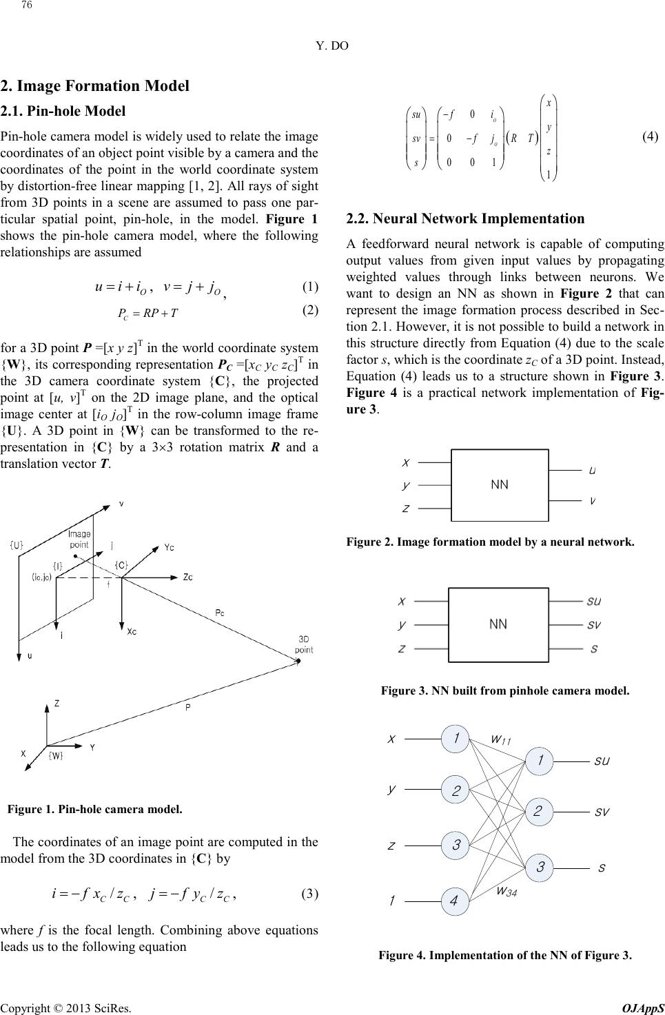 Y. DO Copyright © 2013 SciRes. OJAppS 2. Image Formation Model 2.1. Pin-hole Model Pin-hole camera model is widely used to relate the image coordinates of an object point visible by a camera and the coordinates of the point in the world coordinate system by distortion-free linear mapping [1, 2]. All rays of sight from 3D points in a scene are assumed to pass one par- ticular spa tial point, pin-hole , in the model. Fig ure 1 shows the pin-hole camera model, where the following relationships are assumed O uii= + , O vjj= + , (1) C PRP T= + (2) for a 3D point P =[x y z]T in the world coordinate system {W}, its corresponding representation PC =[xC yC zC]T in the 3D camera coordinate system {C}, the projected point at [u, v]T on the 2D image plane, and the optical image center at [iO jO]T in the row-column image frame {U}. A 3D point in {W} can be transformed to the re- presentation in {C} by a 3×3 rotation matrix R and a translation vector T. Figure 1. Pin-hole camera model. The coordinates of an image point are computed in the model from the 3D coordinates in {C} by / CC ifx z= − , / CC jfyz= − , (3) where f is the focal lengt h. Combining above equations leads us to the following eq uatio n (4) 2.2. Neural Network Implementation A feedforward neural network is capable of computing output values from given input values by propagating weighted values through links between neurons. We want to design an NN as shown in Figure 2 that can represent the image formation process described in Sec- tion 2.1. However, it is not possible to build a network in this structure directly from Equation (4) due to the scale factor s, which is the coordinate zC of a 3D point. Instead, Equation (4) leads us to a structure shown in Figure 3. Figure 4 is a practical network implementatio n of Fig- ure 3. Figure 2. Image formation model by a neural network. Figure 3. NN built from pinhole camera model. Figure 4. Implementation of the NN of Figure 3. ( ) 0 0 0 01 1 O O x su fi y svfjR T z s − = − x y z su sv s 1 w 11 w 34 1 3 2 3 4 1 2 76  Y. DO Copyright © 2013 SciRes. OJAppS Like most other NNs and their applications, the key issue of the NN implementation presented in Figure 4 is determining the weight of each link between neurons. From Equation (4), the physical meaning of wnm, a link weigh t from neuron m to neuron n, can be spe cified as (5) where rpq are elements of rotation matrix R, and tp are elements of translation vector T; 1≤ p, q ≤3. The network shown in Figure 4 has a quite simple structure. However, it is not simple to train the NN be- cause we do not know the scale factor s for a given 3D point P. We know only the projected image coordinates u and v for a control point P. If the desired output is not available, it is not possible to train the network using a supervised learning algorithm, such as gradient descent optimization [13]. We thus need to develop a method to train the network in the structure of Figure 4. An error function is defined as (6) where e1=o1/o3 − u, e2=o2/o3 − v, e3=((o1o2)/(uv))1/2 − o3 for three computed output neuron values, o1, o2, and o3. Note that the error term of the 3rd output neuron, e3, is derived from (7) Then, the weights are trained by gradient descent. For a weight wnm, n=1 or 2, as shown in Figure 5, a chain rule is applied to the given error E as (8) where, assuming a linear activation function for output neurons, nn Ee e∂∂= , 3 1/ nn eo o∂ ∂= , 1 nn og ∂ ∂= , nnm n gw o∂∂= . For the case of n=3, on the other hand, the following equation can be obtained by gradient descent, . (9) Figure 5. Connection between an input neuron m and an output neuron n. 3. Numerical Example A camera is assumed to be located at x= − 200, y=500, z=2000 and oriented by Z-Y-X Euler angles of θz=45°, θy= − 30° and θx=120° in the world coordinate system {W}. It is also assumed that the focal length is f=25, the coor- dinates of the optical image center is (258, 204), and the dimension of a pixel is 0.023×0.023. This camera setup is drawn in Figure 6. An NN can then be built to express the image formation process of the camera as presented in Figure 7. Figure 6. Camera setup assumed as an example. Figure 7. Neural network resulted from the camera setup. 4. Concluding Remarks We have shown that a feedforward neural network can be o n w nm m n o m g n 2 12 ()( ).o osusvsuv= = 222 123 ( )/2Ee ee= ++ nn n nmn nnnm eo g EE w eogw ∂∂ ∂ ∂∂ = ∂ ∂∂∂∂ 33 /mm e Ew o = − ∂∂ 111131 121232 ,, OO wfri rwfri r=−+ =−+ 131333 1413 ,, OO wfrirwfti t=− +=−+ 212131 222232 ,, OO wfrj rwfrjr=−+ =−+ 232333 2423 ,, OO wfrj rwftjt=− +=−+ 31 31 wr= , 3232 wr =, 33 33 wr= , 34 3 wt =, x y z 1 s -11 3 1 -18 14 -15 -21 36961 34842 1242 u v 1/s 1/s 77  Y. DO Copyright © 2013 SciRes. OJAppS constructed to express the image formation process of a camera. The network constructed in this paper is in a quite simple structure with four input neurons and three output neurons of linear activation functions. Although most existing applications of NNs to camera modeling have focused on nonlinear lens distortion problem, the network of this paper models the linear perspective transfor mation. A method to learn the link weights be- tween neurons of the proposed network is also described. The entire image formation of a camera may be modeled accurately if the proposed network is combined with an existing NN-based method developed for correcting lens distortion. 5. Acknowledgemen t This research was supported by Basic Science Research Program through the National Research Foundation of Korea(NRF) funded by the Ministry of Education, Science and Technology(2012R1A1A4A01010160). REFERENCES [1] R. Szeliski, “Computer Vision, Algorithms and Applica- tions,” Springer-Verlag, London, 2011. [2] R. Y. Tsai, "A Versatile Camera Calibration Technique for High Accuracy 3D Machine Vision Metrology Using Off-the-Shelf TV Cameras and Lenses", IEEE Journal of Robotics and Automation, Vol. 3, No. 4, 1987, pp. 323-344. [3] K. Nakano, M. Okutomi and Y. Hasegawa, "Camera Ca- libration with Precise Extraction of Feature Points Using Projective Transformation," Proceedings of IEEE Inter- national Conference on Robotics and Automation, Vol. 3, 2002, pp. 2532-2538. doi:10.1109/JRA.1987.1087109 doi:10.1109/ROBOT.2002.1013612 [4] J. Weng, P. Cohen, M. Herniou, "Camera Calibration with Distortion Models and Accuracy Evaluation," IEEE Transactions on Pattern Analysis and Machine Intelli- gence, Vol. 14, Issue. 10, pp. 965-980, 1992. doi:10.1109/34.159901 [5] K. D. Gremba n, C. E. Thorpe, T. Kanade, "Geometric Camera Calibration Using Systems of Linear Equations," Proceedings of IEEE Conference on Robotics and Auto- mation, 1988, pp. 562-567. doi:10.1109/ROBOT.1988.12111 [6] R. Hartley and A. Zisserman, “Multiple View Geometry in Computer Vision”, Cambridge University Press, 2000. [7] B. Triggs, “Autocalibration from Planar Scenes,” Pro- ceedings of European Conference on Computer Vision, 1998, pp. 89-105. [8] Z. Zhang, “A Flexible New Technique for Camera Cali- bration,” IEEE Transactions on Pattern Analysis and Machine Intelligence, Vol. 22, Issue. 11, 2000, pp. 1330-1334. doi:10.1109/34.888718 [9] Q. Wang, L. Fu and Z. Liu, “Review on Camera Calibra- tion,” Proceedings of Chinese Control and Decision Conference, 2010, pp. 3354-3358. [10] J. Salvi, X. Armangué and J. Batlle, “A Comparative Review of Camera Calibrating Methods with Accuracy Evaluation,” Pattern Recognition, Vol. 35, Issue 7, 2002, pp. 1617-1635. doi:10.1016/S0031-3203(01)00126-1 [11] X. Chen, H. Fang, Y. Yang and S. Qin, “The Research of Camera Distortion Correction Basing on Neural Net- work,” Pro ceedings of Chinese Control and Decision Conference, 2011, pp. 596-601. [12] J. – P. Tardif, P. Sturm, M. Trudeau and S. Roy, “Cali- bration of Cameras with Radially Symmetric Distortion,” IEEE Transactions on Pattern Analysis and Machine In- telligence, Vol. 31, Issue 9, 2009, pp. 1552-1566. doi:10.1109/TPAMI.2008.202 [13] C. M. Christopher, “Pattern Recognition and Machine Learning”, Springer Science + Business Media, New York, 2006. 78 |