

Paper Menu >>
Journal Menu >>
 J. Biomedical Science and Engineering, 2010, 3, 927-930 doi:10.4236/jbise.2010.39123 Published Online September 2010 (http://www.SciRP.org/journal/jbise/ JBiSE ). Published Online September 2010 in SciRes. http:// www.scirp.org/journal/jbise Design and research of measuring system of clamping force of hemostats Huifang Wang, Shuyi Wang, Ying Zhou, Jie Tan School of Medical Instrument and Food Engineering, University of Shanghai for Science and Technology, Shanghai, China. Email: [email protected] Received 15 July 2010; revised 25 July 2010; accepted 28 July 2010. ABSTRACT Reliability of medical instruments such as hemostats is extremely important because these instruments are used in patients who are in critical condition. Clam- ping force of hemostats, as an important parameter of hemostats, should be detected. However, it could not be tested directly. In order to test it, a testing sys- tem has been put forward. The system is comprised of sensor, acquisition card, and three-way tap and so on. This system is controlled by a computer. The tes- ting system has been proved to be effective in testing the clamping force of hemostats. Keywords: Hemostat; Clamping Force; Measuring Sys- tem 1. INTRODUCTION A hemostat is a vital surgical tool used in almost any su- rgical procedure, usually to control bleeding. Hemostats belong to a group of instruments that pivots (similar to scissors, includes needle holders, tissue holders and var- ious clamps), and where the structure of the tip determ- ines their function. Hemostats have handles that can be held in place by the locking mechanism. The locking mechanism is typically a series of interlocking teeth, a few on each handle that allow the user to adjust the cla- mping tension of the pliers [1]. However, pressure val- ues are different regarding to different hemostats. Medical equipment manufacturers can produce many kinds of hemostats, but inspection standard and inspec- tion method of hemostats remain be not researched and improved, especially clamping force of hemostats rem- ains cannot be tested directly or indirectly. However, clinicians or inspection personn el both hope to know the quantitative pressure. In both at home and abroad, clamp pressure measure- ement has been fixed in the field of auto and robots. In brake-by-wire systems of auto, central controllers requ- ire accurate information about the clamp force between the brake pad and the disc as a function of pad displ- acement, which is usually denoted as the characteristic curve of the caliper. Due to aging, temperature, and oth- er environmental variations, caliper characteristic curves vary with time. Therefore, automatic caliper calibration in real-time is vital for high-performance braking action and vehicle safety [2]. In robots, firstly design machine gripper according to the features of the object of holding. Secondly analyzes forces of all parts of machine gripper. At last, derivate clamp pressure force according to the principle of torque. In these machine grippers some are two-finger translation grippers [3] and some are curved arm type hydraulic grab with four bar linkage [4]. There are hardly some studies in clamp pressure measurement of hemostats. Existing pressure sensors in shape and size and fatigue resistance level are unable to satisfy the special needs of these medicinal hemostats, so direct measurement of cla- mping force of hemostats needs design special sensor system. However the sensor system has not been worked out so far according to my study. So some attentions have been focused on finding an indirect measurement method. An indirect measurement method is proposed in this paper. Through testing pressure changes of a clamping catheter filled with liquid, clamping force of hemostats can be reflected indirectly. 2. METHODS AND APPARATUS 2.1. Description of Apparatus Measuring system of clamping force of hemostats is designed which is shown in Figure 1. The testing system can be divided into two parts acco - rding to their different functions. Part 1: In this part, hardware principle of the test syst- em is provided. Functions of each component as follows: 1) Injector: Eliminate air and fill liquid in the whole system. 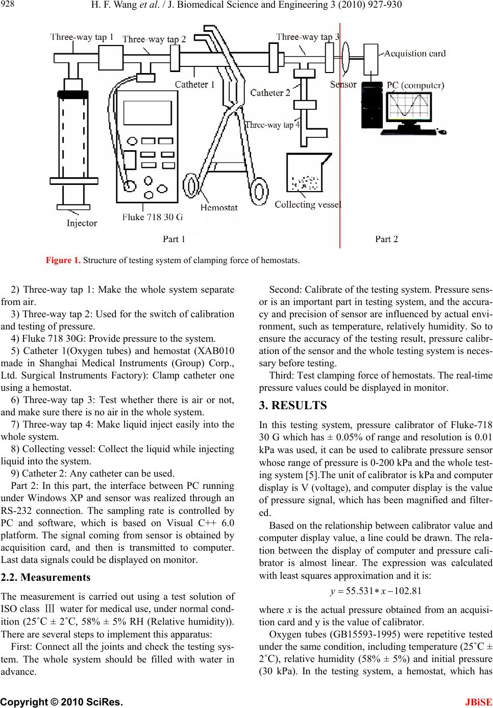 H. F. Wang et al. / J. Biomedical Science and Engineering 3 (2010) 927-930 Copyright © 2010 SciRes. JBiSE 928 Figure 1. Structure of testing system of clamping force of hemostats. 2) Three-way tap 1: Make the whole system separate from air. 3) Three-way tap 2: Used for the switch of calib ration and testing of pressure. 4) Fluke 718 30G: Provide pressure to the system. 5) Catheter 1(Oxygen tubes) and hemostat (XAB010 made in Shanghai Medical Instruments (Group) Corp., Ltd. Surgical Instruments Factory): Clamp catheter one using a hemostat. 6) Three-way tap 3: Test whether there is air or not, and make sure there is no air in the whole system. 7) Three-way tap 4: Make liquid inject easily into the whole system. 8) Collecting vessel: Collect the liqu id while injecting liquid into the system. 9) Cathet er 2 : Any cathet er can be used. Part 2: In this part, the interface between PC running under Windows XP and sensor was realized through an RS-232 connection. The sampling rate is controlled by PC and software, which is based on Visual C++ 6.0 platform. The signal coming from sensor is obtained by acquisition card, and then is transmitted to computer. Last data signals could be displayed on monitor. 2.2. Measurements The measurement is carried out using a test solution of ISO class Ⅲ water for medical use, under normal cond- ition (25˚C ± 2˚C, 58% ± 5% RH (Relative humidity)). There are several steps to implement this apparatus: First: Connect all the joints and check the testing sys- tem. The whole system should be filled with water in advance. Second: Calibrate of the testin g system. Pressure sens- or is an important part in testing system, and the accu ra- cy and precision of sensor are influenced by actual envi- ronment, such as temperature, relatively humidity. So to ensure the accuracy of the testing result, pressure calibr- ation of the sensor and the whole testing system is neces- sary before testing. Third: Test clamping force of hemostats. The real-time pressure va l ue s could be di splayed in monitor . 3. RESULTS In this testing system, pressure calibrator of Fluke-718 30 G which has ± 0.05% of range and resolution is 0.01 kPa was used, it can be used to calibrate pressure sensor whose rang e of pressur e is 0-20 0 kPa and the wh ole test- ing system [5].The unit of calibrator is kPa and computer display is V (voltage), and computer display is the value of pressure signal, which has been magnified and filter- ed. Based on the relationship between calibrator value and computer display value, a line could be drawn. The rela- tion between the display of computer and pressure cali- brator is almost linear. The expression was calculated with least squares approx imation and it is: 55.531 102.81yx where x is the actual pressure obtained from an acquisi- tion card and y is the value of calibrator. Oxygen tubes (GB15593-1995) were repetitive tested under the same condition, including temperature (25˚C ± 2˚C), relative humidity (58% ± 5%) and initial pressure (30 kPa). In the testing system, a hemostat, which has 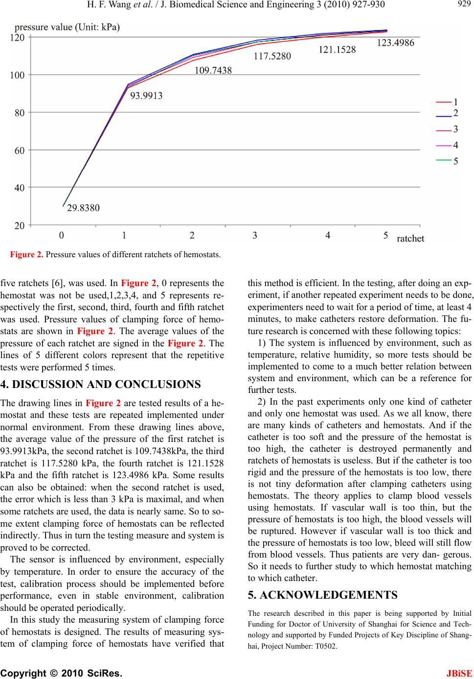 H. F. Wang et al. / J. Biomedical Science and Engineering 3 (2010) 927-930 Copyright © 2010 SciRes. JBiSE 929 Figure 2. Pressure values of different ratchets of hemostats. five ratchets [6], was used. In Figure 2, 0 represents the hemostat was not be used,1,2,3,4, and 5 represents re- spectively the first, second, third, four th and fifth ratchet was used. Pressure values of clamping force of hemo- stats are shown in Figure 2. The average values of the pressure of each ratchet are signed in the Figure 2. The lines of 5 different colors represent that the repetitive tests were performed 5 times. 4. DISCUSSION AND CONCLUSIONS The drawing lines in Figure 2 are tested results of a he- mostat and these tests are repeated implemented under normal environment. From these drawing lines above, the average value of the pressure of the first ratchet is 93.9913kPa, the second ratchet is 1 09.7438kPa, the th ird ratchet is 117.5280 kPa, the fourth ratchet is 121.1528 kPa and the fifth ratchet is 123.4986 kPa. Some results can also be obtained: when the second ratchet is used, the error which is less than 3 kPa is maximal, and when some ratchets are used, the data is nearly same. So to so- me extent clamping force of hemostats can be reflected indirectly. Thus in turn the testin g measure and system is proved to be corrected. The sensor is influenced by environment, especially by temperature. In order to ensure the accuracy of the test, calibration process should be implemented before performance, even in stable environment, calibration should be oper a t ed pe ri o di cal l y . In this study the measuring system of clamping force of hemostats is designed. The results of measuring sys- tem of clamping force of hemostats have verified that this method is efficient. In the testing, after doing an exp- eriment, if another repeated experiment needs to be done, experimenters need to wait for a period of time, at least 4 minutes, to make catheters restore deformation. The fu- ture research is concerned with these following topics: 1) The system is influenced by environment, such as temperature, relative humidity, so more tests should be implemented to come to a much better relation between system and environment, which can be a reference for further tests. 2) In the past experiments only one kind of catheter and only one hemostat was used. As we all know, there are many kinds of catheters and hemostats. And if the catheter is too soft and the pressure of the hemostat is too high, the catheter is destroyed permanently and ratchets of hemostats is useless. But if the catheter is too rigid and the pressure of the hemostats is too low, there is not tiny deformation after clamping catheters using hemostats. The theory applies to clamp blood vessels using hemostats. If vascular wall is too thin, but the pressure of hemostats is too high, the blood vessels will be ruptured. However if vascular wall is too thick and the pressure of hemostats is too low, bleed will still flow from blood vessels. Thus patients are very dan- gerous. So it needs to further study to which hemostat matching to which catheter. 5. ACKNOWLEDGEMENTS The research described in this paper is being supported by Initial Funding for Doctor of University of Shanghai for Science and Tech- nology and supported by Funded Projects of Key Discipline of Shang- hai, Project Number: T0502.  H. F. Wang et al. / J. Biomedical Science and Engineering 3 (2010) 927-930 Copyright © 2010 SciRes. JBiSE 930 REFERENCES [1] http://www.answers.com/topic/hemostat [2] Hoseinnezhad, R., Bab-Hadiashar, A. and Rocco, T. (2008) Real-time clamp force measurement in electromechanical brake calipers. IEEE Vehicular Technology Society, 57(2), 770-777. [3] Su, Z.H. and Kong, Q.Z. (2008) Design of two- finger translation gripper of articulated robot. Mechanical En- gineering & Automation, (5), 80-84. [4] Ma, Z.S., Bian, X.L. and Chu, X.J. (2008) Design and performance simulation for grab on emergency engi- neering robot. Engineering Machinery, 39(7), 25-28. [5] Pressure Calibrator 718 Product. [6] Zhang, H.Y., Li, B. and Xu, Z.T. (2008) Maintenance and inspection of surgical instrument. Operation & Maintenance, 29(9), 126. |