

Paper Menu >>
Journal Menu >>
 Journal of Analytical Sciences, Methods and Instrumentation, 2012, 2, 203-207 http://dx.doi.org/10.4236/jasmi.2012.24031 Published Online December 2012 (http://www.SciRP.org/journal/jasmi) 203 System for High Throughput Water Extraction from Soil Material for Stable Isotope Analysis of Water Timothy S. Goebel, Robert J. Lascano* Wind, Erosion, and Water Conservation Research Unit, Cropping Systems Research Laboratory USDA-ARS#, Lubbock, USA. Email: *[email protected] Received September 25th, 2012; revised October 26th, 2012; accepted November 2nd, 2012 ABSTRACT A major limitation in the use of stable isotop e of water in ecological studies is the time that is required to extract water from soil and plant samples. Using vacuum distillation the extraction time can be less than one hour per sample. There- fore, assembling a distillation system that can process multiple samples simultaneously is advantageous and necessary for ecological or hydrological investigations. Presented here is a vacuum distillation apparatus, having six ports, that can process up to 30 samples per day. The distillation system coupled with the Los Gatos Research DLT-100 Liquid Water Isotope Analyzer is capable of analyzing all of th e samples that are generated by vacuum distillatio n. These two systems allow larger sampling rates making investigations into water movement through an eco logical system possible at higher temporal and spatial resolution. Keywords: Isotope; Vacuum Distillation; Soil 1. Introduction Stable Isotopes of water have been studied in the fields’ of ecology and geology since the 1950’s with increased attention over the last 30 years [1-6]. Historically the sam- ples were analyzed using isotope ratio mass spectrometry (IRMS) that requires the evolution of the sample into a gas. This process is very sensitive; however, it is also very time consuming [3]. With the advent of instrument- tation using off-axis integrated cavity output spectros- copy (OA-ICOS), such as the Liquid Water Stable Iso- ope Analyzer (LIWA) DLT-100 from Los Gatos Inc. or the L2130 from Picarr o Inc., the time required to analyze samples is no longer the bottleneck in sample pro cessing for stable isotope analysis [7]. Currently, the major bot- tleneck for studying stable isotopes has shifted to the time required for complete extraction of water from soil samples collected from the field [8]. The larger the num- ber of samples taken in the field the greater the temporal and spatial resolution the samples will represent. There are several different extraction methods currently used to extract water from plant and soil samples. Examples of distillation meth ods include azio tropic and cryog enic dis- tillation techniques [9-12]. The objective was to develop a multi-port water extraction system capable of produc- ing unfractionated water samples from multiple soil sam- ples in a day. Presented here are the details of the design of a cryogenic vacuum distillation system. This system follows the port design developed by West et al. [8] having six ports that allow extraction of several sets of soil samples in a day. A manifold that allows the iso- lation of individual ports for troubleshooting and main- tenance connects these ports. 2. Experimental 2.1. Build Details 2.1.1. Assembly of Extraction Port The most basic component of the Vacuum Distillation System is the port as illustrated in Figure 1. The port connects the ignition tube and the collection test tube to the vacuum. The ignition tube (Pyrex, Ignition Tube, 25 200 mm, Rimless, Heavy Wall, # 9860-25) contains the soil or plant material. It is connected to the glass “T” by a custom made Swagelok adapter (# 8 in Figure 1). The collection tube (Pyrex, Tube, 12 75 mm, Rimless, # 9820-12) contains the water extracted from the soil sam- ple. It is connected to the glass “Tee” by another cus- tom-ma de Sw agelok ad aptor (# 9 in Figure 1). The glass “Tee” is a custom-made glass piece made by “Q” Glass *Corresponding a uthor. #The US Department of Agriculture (USDA) prohibits discrimination in all its programs and activities on the basis of race, color, national origin, age, disability, and where applicable, sex, marital status, famil- ial status, parental status, religion, sexual orientation, genetic informa- tion, political beliefs, reprisal, or because all or part of an individual’s income is derived from any publi c assistance program. Copyright © 2012 SciRes. JASMI 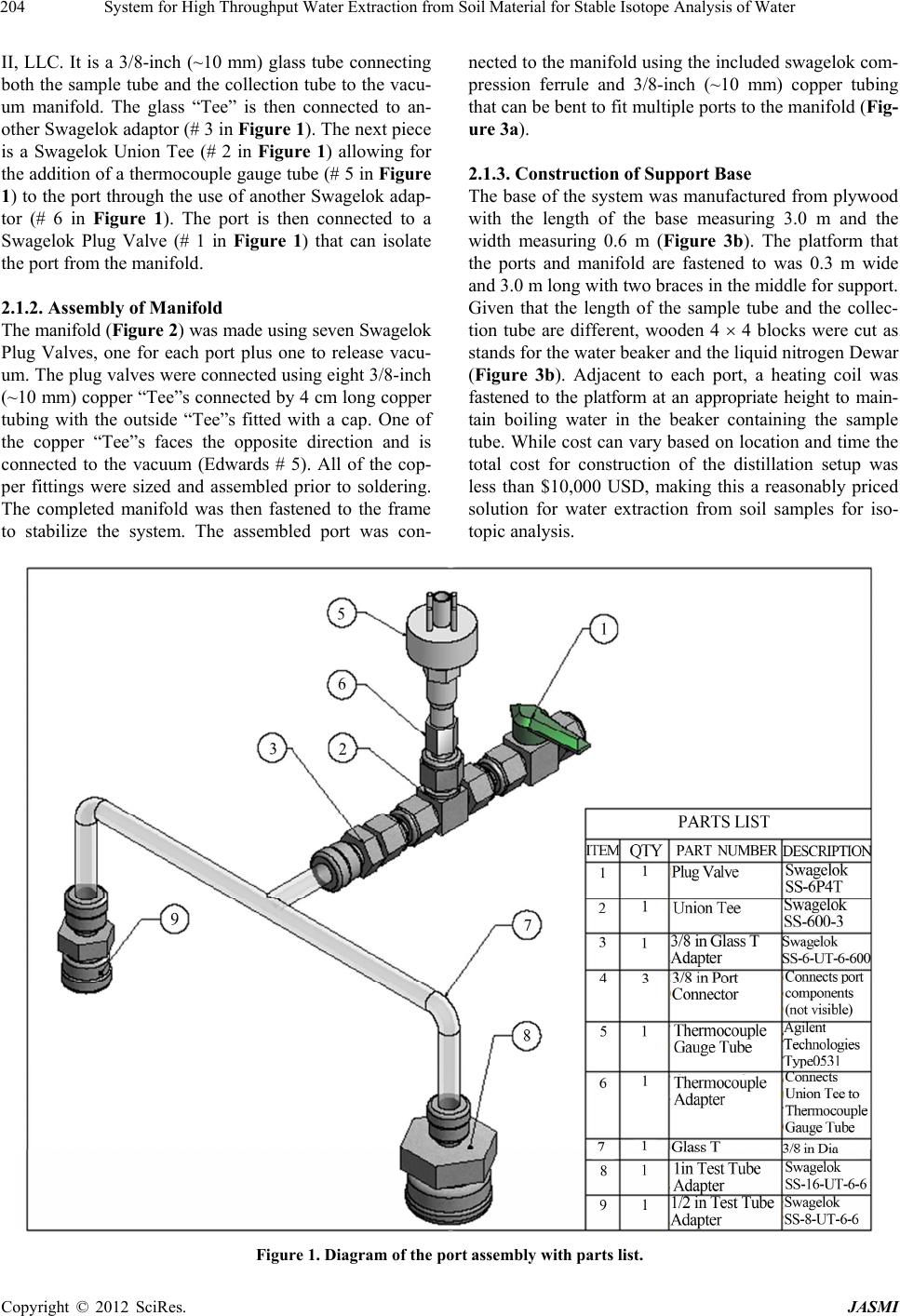 System for High Throughput Water Extraction from Soil Material for Stable Isotope Analysis of Water 204 II, LLC. It is a 3/8-inch (~10 mm) glass tube connecting both the sample tube and the collection tube to the vacu- um manifold. The glass “Tee” is then connected to an- other Swagelok adaptor (# 3 in Figure 1). The next piece is a Swagelok Union Tee (# 2 in Figure 1) allowing for the addition of a thermocoup le gauge tube (# 5 in Figure 1) to the port through the use of another Swagelok adap- tor (# 6 in Figure 1). The port is then connected to a Swagelok Plug Valve (# 1 in Figure 1) that can isolate the port from the manifold. 2.1.2. Assembl y of Mani f ol d The manifold (Figure 2) was made using seven Swagelok Plug Valves, one for each port plus one to release vacu- um. The plug valves were connected using eight 3/8-inch (~10 mm) copper “Tee”s connected by 4 cm long copper tubing with the outside “Tee”s fitted with a cap. One of the copper “Tee”s faces the opposite direction and is connected to the vacuum (Edwards # 5). All of the cop- per fittings were sized and assembled prior to soldering. The completed manifold was then fastened to the frame to stabilize the system. The assembled port was con- nected to the manifold using the included swagelok com- pression ferrule and 3/8-inch (~10 mm) copper tubing that can be bent to fit multiple ports to the manifold (Fig- ure 3a). 2.1.3. Construction of Support Base The base of the system was manufactured from plywood with the length of the base measuring 3.0 m and the width measuring 0.6 m (Figure 3b). The platform that the ports and manifold are fastened to was 0.3 m wide and 3.0 m long with two braces in th e middle f or sup por t. Given that the length of the sample tube and the collec- tion tube are different, wooden 4 4 blocks were cut as stands for the water beaker and the liquid nitrogen Dewar (Figure 3b). Adjacent to each port, a heating coil was fastened to the platform at an appropriate height to main- tain boiling water in the beaker containing the sample tube. While cost can vary based on location and time the total cost for construction of the distillation setup was less than $10,000 USD, making this a reasonably priced solution for water extraction from soil samples for iso- topic analysis. Figure 1. Diagram of the port assembly with parts list. Copyright © 2012 SciRes. JASMI  System for High Throughput Water Extraction from Soil Material for Stable Isotope Analysis of Water 205 2.2. Soil Sample Collection and Preparation Soil samples were collected from a field adjacent to the USDA-ARS research facility in Lubbock Texas, USA (33˚3540 N, 101˚54'00 W). The soil texture was a sandy clay loam and was ground and passed through a 2-mm sieve before being oven dried at 225˚C for 24 hours. From the bulk sample, 10 g of soil was weighed and added to a pre-weighed ignition tube. The ignition tube was then weighed again. One mL of water was then added to the soil in the ignition tube and the weight was taken again. Glass wool was then added to the ignition tube to prevent soil loss during the ex traction process an d the ignition tube was weighed again. The ignition tube was then sealed with a rubber stopper and placed in a freezer until it is time for extraction. 2.3. Extraction Procedure The process of extraction begins by removing the sam- ple-tube from the freezer and placing in LN2 (liquid Ni- trogen). Next, the collection tube is placed on the port with a “dummy” sample-tube. The vacuum is applied to the system and allowed to draw down for 20 minutes to remove any possible water contamination. During this process the plug valve on the port was turned off to iso- late the port from the vacuum to check for leaks. The port should hold vacuum at <0.013 kPa (100 milliTorr) or adaptors should be tightened unt i l 0.013 kPa is achi eved and maintained. The vacuum is then released and the “dummy” tube is removed and replaced with sample-tube frozen in LN2. The LN2 Dewar is placed under the sample-tube to maintain the temperature at –210˚C preventing any loss of water from the sample as vacuum is applied to the port. The vacuum is then drawn down <0.013 kPa and the system is again checked for leaks. If a leak is present it must be from the adap tor connected to th e sample tu be as Figure 2. Diagram of manifold. the other junctions were tested previously. Once the port is isolated from the vacuum pump and is holding vacuum the LN2 Dewar is removed from the sample side of the port and placed under the collection tube. A 1000 mL beaker was placed under the sample tube and boiling water was poured into the beaker up to the top of the heating mantle and a timer was started. The amount of time the sample was allowed to distill was varied between 4 and 90 minutes for each soil sam- ple. When the distillation ti me was complete the vacuum was released from the port and the collection tube was removed from the port, sealed with parafilm®, and placed in a water bath to thaw. Once the collectio n tube is in the bath, the sample-tube is removed from the port and al- lowed to cool before weighing. All water samples that were collected were then analyzed using a LGR-DLT 100 Liquid Water Isotope Analyzer following the IAEA procedure for analysis of stable isotopes [13]. 3. Results and Discussion When using vacuum distillation it is imperative that the resulting water extract be unfractionated. However, the distillation process follows a Rayleigh distillation curve where the heaver water (i.e., ) will condense first and the lighter water (i.e., ) being condensed last. This process creates a fractionated sample if the distilla- tion process is stopped before all of the water has been evaporated from the sample and condens ed in the collec- tion tube. Calibration of the extraction timing is an es- sential first step to develop a protocol that can be used in the extraction system for stable isotope measurements. As an example of this protocol, results from the calibra- tion of the different ports are shown in Figure 4. These results clearly show that the minimum extraction time required to develop an unfractiona ted water sample from soil samples is 30 minutes, based on both the isotope signature as well as the percent water. There was no dif- ference in the extraction times between the different ports regardless of the distance from the vacuum source. While the minimum extraction time was found to be 30 minutes, in our labor atory we use one h our as our stand ard extrac- tion time. This allows enough time to start all six ports and the time necessary to make adjustments to a port before the hour is up on first po rt. 18 2 HO 16 2 HO 4. Conclusion The distillation apparatus described allows for a high throughput water extraction from soil samples. The sys- tem has six ports that allow us to extract 30 or more samples in a 8-hour working day using one hour as the standard extraction time. This system in conju nction with the LGR DLT-100 allows for the extraction and analysis of 30 samples per day making it possible to study water Copyright © 2012 SciRes. JASMI  System for High Throughput Water Extraction from Soil Material for Stable Isotope Analysis of Water 206 (a) (b) Figure 3. (a) Diagram of the copper tubing used to connect the manifold to the six ports; (b) Photograph of the assembled distillation apparatus. Figure 4. Extraction timing curves for each port. The δ18O is represented by and the water content is represented by . he dashed line represents the minimum extraction time to obtain an unfractionated water sample. T Copyright © 2012 SciRes. JASMI  System for High Throughput Water Extraction from Soil Material for Stable Isotope Analysis of Water 207 movement in the soil at a higher spatial and temporal resolution than has been previously used. Extraction times may vary based on the soil type, e.g., clay vs. sand, and as such calibration should be performed for differing soil types. The system described here can also be used to ex- tract water form plant material such as leaves and stems; however, some concern has been noted about the inter- ference of organics that can co-distill with the water causing errors in the spectroscopic analysis of these wa- ter samples [14,15]. More recently, a study has shown that it is possible to calibrate the instrument for these types of contaminants and remove the interference from the measurement [16]. The possibility of using this ex- traction technique for analysis of samples from both soil and plant material makes this a simple cost effective sys- tem for in depth analysis of water movement through an ecosystem. 5. Acknowledgements This research was supported in part by the Ogallala Aq- uifer Program, a consortium between USDA-Agricultural Research Service, Kansas State University, Texas Agri- Life Research, Texas AgriLife Extension Service, Texas Tech University, and West Texas A&M University. We would like to thank Blake Bradley for his help in developing the drawings of the apparatus. We would also like to thank Ja mey Deusterhaus and Jill Booker for their help and insight. Mention of trade names or commercial products in this publication is solely for the purpose of providing specific information and does not imply recommendation or en- dorsement by the US Department of Agriculture. REFERENCES [1] F. E. Wickman, “Variations in the Relative Abundance of the Carbon Isotopes in Plants,” Geochemica et Cosmo- chemica Acta, Vol. 2, No. 4, 1952, pp. 243-254. doi:10.1016/0016-7037(52)90018-5 [2] C. D. Keeling, “The Concentration and Isotopic Abun- dances of Atmospheric Carbon Dioxide in Rural Areas,” Geochemica et Cosmochemica Acta, Vol. 13, No. 4, 1958, pp. 322-334. doi:10.1016/0016-7037(58)90033-4 [3] C. D. Keeling, “The Concentration and Isotopic Abun- dances of Atmospheric Carbon Dioxide in Rural and Ma- rine Air,” Geochemica et Cosmochemica Acta, Vol. 24, No. 3-4, 1961, pp. 277-298. doi:10.1016/0016-7037(61)90023-0 [4] R. Park and S. Epstein, “Metabolic Fractionation of 13C & 12C in Plants,” Plant Physiology, Vol. 36, No. 2, 1961, pp. 133-138. doi:10.1104/pp.36.2.133 [5] T. E. Dawson, S. Mambelli, A. H. Plamboek, P. H. Tem- pler and K. P. Tu, “Stable Isotopes in Plant Ecology, ” An- nual Review Ecological Systems, Vol. 33, 2002, pp. 507- 559. doi:10.1146/annurev.ecolsys.33.020602.095451 [6] L. B. Flanagan, J. E. Ehleringer and D. E. Pataki, “Stable Isotopes and the Biosphere-Atmosphere Interactions,” In: H. A. Mooney, Ed., Physiological Ecology, Elsevier, San Diego, 2005. pp. 9-28. [7] P. Gupta, D. Noone, J. Galewsky, C. Sweeney and B. Vaughn, “Demonstration of High-Precision Continuous Measure- ments of Water Vapor Isotopologues in Laboratory and Remote Field Deployments Using Wavelength-Scanned Cavity Ring-Down Spectroscopy,” Rapid Communications Mass Spectrometry, Vol. 23, No. 16, 2009, pp. 2534-2542. doi:10.1002/rcm.4100 [8] A. G. West, S. J. Patrickson and J. R. E hleringer, “Wa ter Extraction Times for Plant and Soil Materials Used in Sta- ble Isotope Analysis,” Rapid Communications Mass Spec- trometry, Vol. 20, No. 8, 2006, pp. 1317-1321. doi:10.1002/rcm.2456 [9] K. Revesz and P. H. Woods, “A Method to Extract Soil Water for Stable Isotope Analysis,” Journal of Hydrology Vol. 115, No. 1-4, 1990, pp. 397-406. doi:10.1016/0022-1694(90)90217-L [10] J. R. Ehleringer and C. B. Osmond, “Stable Isotopes,” In: R. W. Pearcy, J. R. Ehleringer, H. A. Mooney and P. W. Rundel, Eds., Plant Physiological Ecology: Field Meth- ods and Instrumentation, Kluewer, London, 1989, p. 281. [11] F. N. Dalton, “Plant Root Water Extraction Studies Using Stable Isotopes,” In: B. C. Loughman, O. Gaspari kova and J. Kolek, Eds., St ructural and Func tional Aspects of Trans- port in Roots, Kluwer Academic Publishers, Dordrecht, 1989, pp. 151-155. doi:10.1007/978-94-009-0891-8_29 [12] J. R. Ehleringer, J. Roden and T. E. Dawson, “Assessing Ecosystem-Level Water Relations through Stable Isotope Ratio Analyse s,” In: O. Sala, R. Jac kson, H. A. Moon ey and R. Howarth, Eds. , Methods in Ecosystem Science, Springer , New York, 2000, p. 181. doi:10.1007/978-1-4612-1224-9_13 [13] B. Newman, A. Tanweer and T. Kurttas, “IAEA Standard Operating Procedure for the Liquid-Water Stable Isotope Analyser,” 2009. http://www-naweb.iaea.org/napc/ih/documents/other/laser _procedure_rev12 [14] A. West, G. Goldsmith, P. Brooks and T. Dawson, “Dis- crepancies between Isotope Ratio Infrared Spectroscopy and Isotope Ratio Mass Spectrometry from the Stable Isotope Analysis of Plant and Soil Waters,” Rapid Com- munication Mass Spectrometry, Vol. 24, No. 14, 2010, pp. 1948-1954. doi:10.1002/rcm.4597 [15] W. Brand, H. Geilmann, E. Crosson and C. Rella, “Cavity Ring-Down Spectroscopy versus High Temperature Con- version Isotope Ratio Mass Spectrometry; a Case Study of D2H and D18O of Pure Water Samples on Alcohol/ Water Mixtures,” Rapid Communications Mass Spectrome- try, Vol. 23, No. 12, 2009, pp. 1879-1884. doi:10.1002/rcm.4083 [16] N. M. Schultz, T. J. Griffis, X. Lee and J. M. Baker, “Identification and Correction of Spectral Contamination in 2H/1H and 18O/16O Measured in Leaf, Stem and Soil Water,” Rapid Communications Mass Spectrometry, Vol. 25, No. 21, 2011, pp. 3360-3368. doi:10.1002/rcm.5236 Copyright © 2012 SciRes. JASMI |