

Paper Menu >>
Journal Menu >>
 World Journal of Mechanics, 2012, 2, 361-368 doi:10.4236/wjm.2012.26041 Published Online December 2012 (http://www.SciRP.org/journal/wjm) Copyright © 2012 SciRes. WJM Effects of Residual Stress on the Hydro-Elastic Vibration of Circular Diaphragm Junfeng Zhao, Song Yu Department of Engineering Mechanics, Shandong University, Jinan, China Email: zhaojunf[email protected] Received October 12, 2012; revised November 11, 2012; accepted November 21, 2012 ABSTRACT The effects of residual stress on the hydro-elastic vibration of circular diaphragm are theoretically investigated by using the added mass approach. The Kirchhoff theory of plates is used to model the elastic thin circular diaphragm on an ap- erture of an infinite rigid wall and in contact with a fluid on one side. The fluid is assumed to be incompressible and inviscid and the velocity potential is used to describe its irrotational motion. A non-dimensional tension parameter is defined, and the effects of the tension parameter on the frequency parameters and mode shapes of the diaphragm in the air are presented. The Hankel transform is applied to solve the fluid-diaphragm coupled system; boundary conditions are expressed by integral equations. Finally, the effects of residual stress on the non-dimensional added virtual mass incremental (NAVMI) factors of the diaphragm contact with a fluid on one side are investigated. It is found that the effects of the residual stress cannot be neglected when the edges of the circular diaphragm are clamped. The effects of residual stress for NAVMI factors can be increases 11% when the non-dimensional tension parameter is 1000. Keywords: Circular Diaphragm; Residual Stress; Hankel Transform; Frequency Parameter; Mode Shape; NAVMI 1. Introduction Micro-machined diaphragm structures are extensively used in micro-electromechanical systems (MEMS) as biosensors in air and in liquid media [1-5]. These sensors are excited by electro-static force so that they vibrate at their resonance frequency. When a biological entity is captured by an electrode of biosensor, the resonant fre- quency will change. The capture mass can be measured by detection of the resonant frequency shift. On the fab- rications of these multilayer micro-diaphragms, a certain amount of residual stress will be developed for a variety of reasons [6-9]. The residual stress bend the micro-dia- phragm downward or upward depending on whether the residual stress is tensile or compressive. Moreover, the residual stress is an important influencing factor for the resonant frequency and sensitivity of the biosensors. Sev- eral researchers investigated the effects of residual stress on the diaphragm’s resonant frequency, either theoreti- cally or by finite element analysis [10-12]. They con- cluded that residual stress stiffens the diaphragm and increases its resonant frequency. But, the vibration char- acteristics of the diaphragm in fluid media don’t studied. The fluid structure interaction problems of plate struc- tures partially or totally immersed in fluid have also re- ceived much attention due to their importance. Kwak [13] and Amabili et al. [14] investigated the effect of fluid on the natural frequencies of circular plates vibrating in contact with an infinite liquid surface. Amabili and Kwak [15] investigated the effect of free-surface waves on free vibrations of circular plates resting on a free surface of infinite liquid domain. Amabili et al. [16] and Liang et al. [17] gave the natural frequencies of annular plates on an aperture of an infinite rigid wall and in contact with a fluid on one side. Bauer [18] presented the coupled hy- dro-elastic frequencies of a liquid in a circular cylindrical rigid container, of which the free liquid surface was fully covered by a flexible membrane or an elastic circular plate. Bauer and Chiba [19] extended the study of Bauer [18] to the structure filled with incompressible viscous liquid. Amabili [20] studied the free vibrations of circular plates resting on a sloshing liquid free surface; the liquid domain was limited by a rigid cylindrical surface and a rigid flat bottom. When the biosensors are used in liquid media, the effect of the fluid on the diaphragm must be investigated [21,22]. However, the residual stress was neglected in these studies. The objective of the present paper is to investigate the effects of residual stress on the hydro-elastic vibration of circular diaphragm. The Kirchhoff theory of plates is used to model the elastic thin circular diaphragm. The governing equation of a circular diaphragm with the re- sidual stress is obtained in Section 2. A non-dimensional tension parameter is defined, and the effects of the ten- 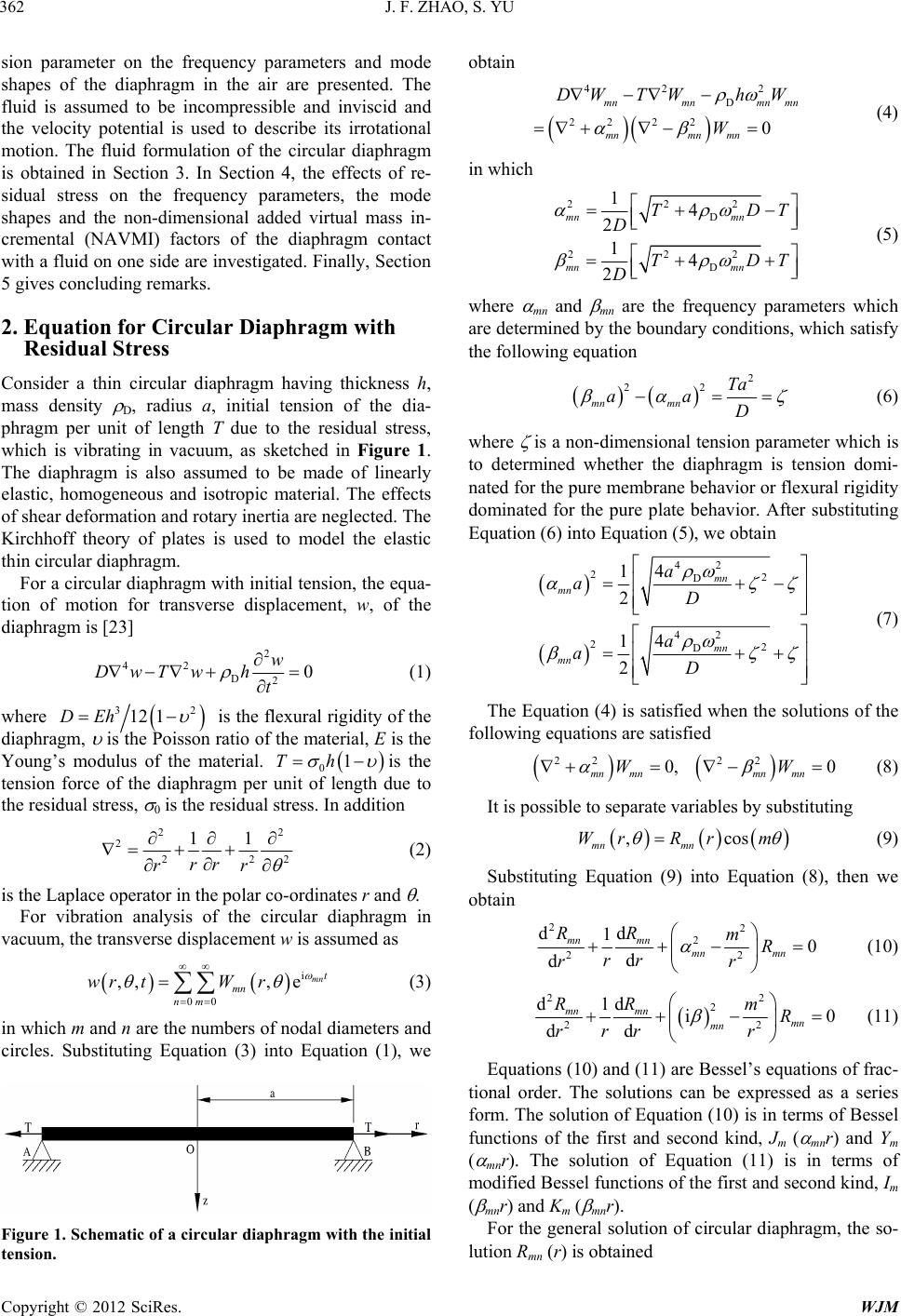 J. F. ZHAO, S. YU Copyright © 2012 SciRes. WJM 362 sion parameter on the frequency parameters and mode shapes of the diaphragm in the air are presented. The fluid is assumed to be incompressible and inviscid and the velocity potential is used to describe its irrotational motion. The fluid formulation of the circular diaphragm is obtained in Section 3. In Section 4, the effects of re- sidual stress on the frequency parameters, the mode shapes and the non-dimensional added virtual mass in- cremental (NAVMI) factors of the diaphragm contact with a fluid on one side are investigated. Finally, Section 5 gives concluding remarks. 2. Equation for Circular Diaphragm with Residual Stress Consider a thin circular diaphragm having thickness h, mass density D, radius a, initial tension of the dia- phragm per unit of length T due to the residual stress, which is vibrating in vacuum, as sketched in Figure 1. The diaphragm is also assumed to be made of linearly elastic, homogeneous and isotropic material. The effects of shear deformation and rotary inertia are neglected. The Kirchhoff theory of plates is used to model the elastic thin circular diaphragm. For a circular diaphragm with initial tension, the equa- tion of motion for transverse displacement, w, of the diaphragm is [23] 2 42 D20 w DwTw h t (1) where 32 12 1DEh is the flexural rigidity of the diaphragm, is the Poisson ratio of the material, E is the Young’s modulus of the material. 01Th is the tension force of the diaphragm per unit of length due to the residual stress, 0 is the residual stress. In addition 22 2 222 11 rr rr (2) is the Laplace operator in the polar co-ordinates r and . For vibration analysis of the circular diaphragm in vacuum, the transverse displacement w is assumed as i 00 ,,, emn t mn nm wr tW r (3) in which m and n are the numbers of nodal diameters and circles. Substituting Equation (3) into Equation (1), we Figure 1. Schematic of a circ ular diaphragm with the initial tension. obtain 42 2 D 22 220 mnmnmnmn mnmn mn DWTWh W W (4) in which 222 D 222 D 14 2 14 2 mn mn mn mn TDT D TDT D (5) where mn and mn are the frequency parameters which are determined by the boundary conditions, which satisfy the following equation 2 22 mn mn Ta aa D (6) where is a non-dimensional tension parameter which is to determined whether the diaphragm is tension domi- nated for the pure membrane behavior or flexural rigidity dominated for the pure plate behavior. After substituting Equation (6) into Equation (5), we obtain 42 22 D 42 22 D 4 1 2 4 1 2 mn mn mn mn a aD a aD (7) The Equation (4) is satisfied when the solutions of the following equations are satisfied 22 22 0, 0 mn mnmn mn WW (8) It is possible to separate variables by substituting ,cos mn mn WrRr m (9) Substituting Equation (9) into Equation (8), then we obtain 22 2 22 dd 10 d d mn mn mn mn RR mR rr rr (10) 22 2 22 dd 1i0 d d mn mn mn mn RR mR rr rr (11) Equations (10) and (11) are Bessel’s equations of frac- tional order. The solutions can be expressed as a series form. The solution of Equation (10) is in terms of Bessel functions of the first and second kind, Jm ( mnr) and Ym ( mnr). The solution of Equation (11) is in terms of modified Bessel functions of the first and second kind, Im ( mnr) and Km ( mnr). For the general solution of circular diaphragm, the so- lution Rmn (r) is obtained 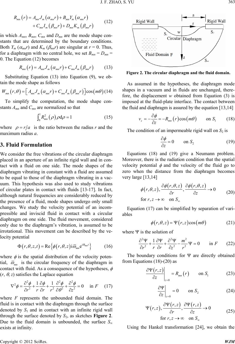 J. F. ZHAO, S. YU Copyright © 2012 SciRes. WJM 363 mnmnm mnmnm mn mnm mnmnm mn Rr AJrBYr CIr DKr (12) in which Amn, Bmn, Cmn and Dmn are the mode shape con- stants that are determined by the boundary conditions. Both Ym ( mnr) and Km ( mnr) are singular at r = 0. Thus, for a diaphragm with no central hole, we set Bmn = Dmn = 0. The Equation (12) becomes mnmnm mnmnm mn Rr AJrCIr (13) Substituting Equation (13) into Equation (9), we ob- tain the mode shape as follows ,cos mnmnm mnmnm mn WrAJ rCIrm (14) To simplify the computation, the mode shape con- stants Amn and Cmn are normalized so that 12 0d1 mn R (15) where ra is the ratio between the radius r and the maximum radius a. 3. Fluid Formulation We consider the free vibrations of the circular diaphragm placed in an aperture of an infinite rigid wall and in con- tact with a fluid on one side. The mode shapes of the diaphragm vibrating in constant with a fluid are assumed to be equal to those of the diaphragm vibrating in a vac- uum. This hypothesis was also used to study vibrations of circular plates in contact with fluids [13-17]. In fact, although natural frequencies are considerably reduced by the presence of a fluid, mode shapes undergo only small changes. We study the velocity potential of an incom- pressible and inviscid fluid in contact with a circular diaphragm on one side. The fluid movement, considered only due to the diaphragm’s vibration, is assumed to be irrotational. This movement can be described by the ve- locity potential i ,,,Re,, iemnt mn rzt rz (16) where is the spatial distribution of the velocity poten- tial, mn is the circular frequency of the diaphragm in contact with fluid. As a consequence of the hypotheses, (r, , z) satisfies the Laplace equation 222 2 2222 11 0in F rr rrz (17) where F represents the unbounded fluid domain. The fluid is in contact with the diaphragm through the surface denoted by S1 and in contact with an infinite rigid wall through the surface denoted by S2, as sketches Figure 2. Due to the fluid domain is unbounded, the surface S exists at infinity. Figure 2. The circular diaphragm and the fluid domain. As assumed in the hypotheses, the diaphragm mode shapes in a vacuum and in fluids are unchanged, there- fore, the displacement w obtained from Equation (3) is imposed at the fluid-plate interface. The contact between the fluid and diaphragm is assured by the equation [13,14] 1 cos on zmn vRrmS z (18) The condition of an impermeable rigid wall on S2 is 2 0onS z (19) Equations (18) and (19) give a Neumann problem. Moreover, there is the radiation condition that the spatial velocity potential and the velocity of the fluid go to zero when the distance from the diaphragm becomes very large [13,14] ,, ,, ,, ,,0 for ,on rz rz rz rz rz S (20) Equation (17) can be simplified by separation of vari- ables ,,, cosrzrzm (21) where is the solution of 222 222 10in m F rr rzr (22) The boundary conditions for are directly obtained from Equations (18)-(20) as 1 0 ,on mn z rz Rr S z (23) 2 0 0on z S z (24) ,, ,, ,0 for ,on rz rz rz rz rz S (25) Using the Hankel transformation [24], we obtain the  J. F. ZHAO, S. YU Copyright © 2012 SciRes. WJM 364 relation 0 ,,d m zrrzJrr (26) By integrating by parts, we can derive the relation 22 22 0 22 0 1d ,d , m m m rJrr rr rr rrzJ rrz (27) At the same time, we have for the third term of Equa- tion (22) 22 22 0 d d, d m rJrrz zz (28) Using Equations (27) and (28) reduces the partial dif- ferential Equation (22) to the ordinary differential equation 2 2 2 d,,0 dzz z (29) Boundary condition Equation (25) requires that the solution of Equation (29) consists of the attenuating part only ,e0 z zBa z (30) where B (a ) is a function that must be determined. From the inversion formula for the Hankel transformation along with Equation (30), we obtain 0 0 ,,d ed m z m rzz Jr BaJ r (31) Inserting Equation (31) into the boundary condition Equations (23) and (24) give 2 0d,0 mmn BaJrRrr a (32) 2 0d0, m BaJrr a (33) Introducing the non-dimensional variables as ,, raA B a (34) The integral Equations (32) and (33) can be written in the following standard form 3 0d,01 mmn AJ aR (35) 0d0, 1 m AJ (36) where mnmnm mnmnm mn RAJaCIa (37) The solution of the integral Equations (35) and (36), can be obtained by using the properties of the Hankel transform [24]. In fact, since the Equation (36) is equal to zero, we obtain 1 33 0d mn mmn AaRJ aH (38) in which [25] mnmnAmnmn Cmn HAH CH (39) 11 22 2 Amn mn mmnmmmnm mn H aJaJJa J a (40) 11 22 2 Cmn mnmmnmmmnm mn H aIaJIa J a (41) Inserting Equation (38) into Equation (31) and using Equation (34), we obtain the function at the fluid-plate interface 0 ,0 d mn m aH J (42) Using the Rayleigh quotient for the coupled vibrations, the squares of the natural frequencies of the diaphragm in a vacuum are proportional to the ratio between the maximum potential energy of the diaphragm VD and its kinetic energy TD [26]. Due to the mode shapes of the diaphragm vibration in constant with a fluid are assumed to be equal to those of the diaphragm vibration in a vac- uum, the squares of the natural frequencies in fluid are proportional to the ratio between the maximum potential energy of the diaphragm VD and the sum of the kinetic energies of both the diaphragm TD and the fluid TF. Therefore, we can obtain 2 vacuum D V D V fT (43) 2 fluid D F DF V fTT (44) Since the mode shapes in a vacuum and in fluids are assumed to be the same, the maximum potential energies VD and the kinetic energy TD are not changed when evaluated in vacuum or in fluids. By using Equations (43) and (44), the following relation between natural frequen- cies in a vacuum fV and natural frequencies in fluids fF is obtained 1 V F mn f f (45) where mn is the added virtual mass incremental (AVMI) factor [13,14]. This factor is given by the ratio between the kinetic energy of the fluids and the kinetic energy of the diaphragm 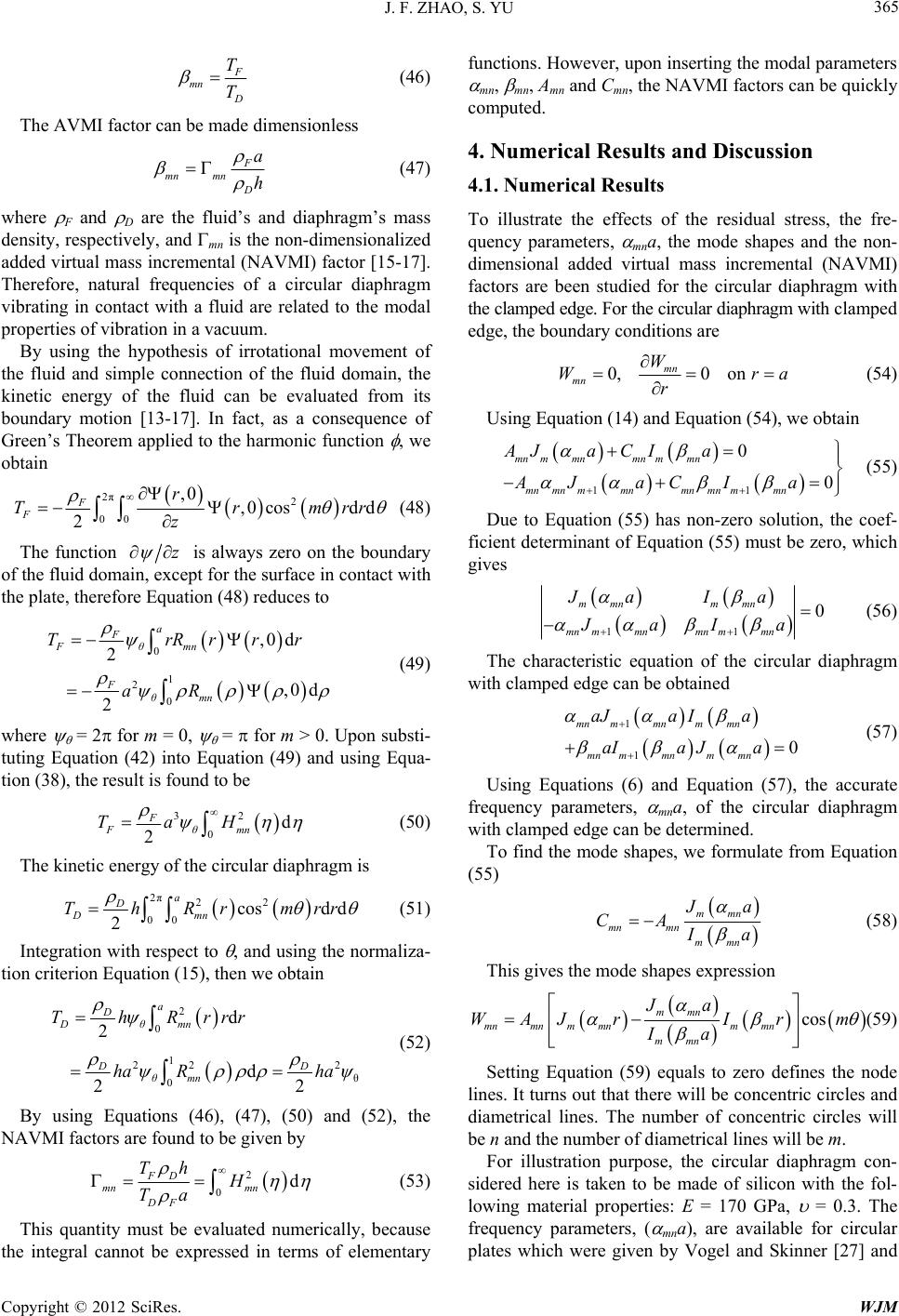 J. F. ZHAO, S. YU Copyright © 2012 SciRes. WJM 365 F mn D T T (46) The AVMI factor can be made dimensionless F mn mn D a h (47) where F and D are the fluid’s and diaphragm’s mass density, respectively, and mn is the non-dimensionalized added virtual mass incremental (NAVMI) factor [15-17]. Therefore, natural frequencies of a circular diaphragm vibrating in contact with a fluid are related to the modal properties of vibration in a vacuum. By using the hypothesis of irrotational movement of the fluid and simple connection of the fluid domain, the kinetic energy of the fluid can be evaluated from its boundary motion [13-17]. In fact, as a consequence of Green’s Theorem applied to the harmonic function , we obtain 2π2 00 ,0 ,0cosd d 2 F F r Trmrr z (48) The function z is always zero on the boundary of the fluid domain, except for the surface in contact with the plate, therefore Equation (48) reduces to 0 1 2 0 ,0 d 2 ,0 d 2 a F Fθmn F θmn TrRrrr aR (49) where = 2 for m = 0, = for m > 0. Upon substi- tuting Equation (42) into Equation (49) and using Equa- tion (38), the result is found to be 32 0d 2 F Fθmn TaH (50) The kinetic energy of the circular diaphragm is 2π22 00 cosdd 2 a D Dmn ThRrmrr (51) Integration with respect to , and using the normaliza- tion criterion Equation (15), then we obtain 2 0 1 22 2 θ 0 d 2 d 22 a D Dθmn DD θmn ThRrrr ha Rha (52) By using Equations (46), (47), (50) and (52), the NAVMI factors are found to be given by 2 0d FD mn mn DF Th H Ta (53) This quantity must be evaluated numerically, because the integral cannot be expressed in terms of elementary functions. However, upon inserting the modal parameters mn, mn, Amn and Cmn, the NAVMI factors can be quickly computed. 4. Numerical Results and Discussion 4.1. Numerical Results To illustrate the effects of the residual stress, the fre- quency parameters, mna, the mode shapes and the non- dimensional added virtual mass incremental (NAVMI) factors are been studied for the circular diaphragm with the clamped edge. For the circular diaphragm with clamped edge, the boundary conditions are 0,0 on mn mn W Wra r (54) Using Equation (14) and Equation (54), we obtain 11 0 0 mnmmnmn mmn mnmnmmnmnmnmmn AJaCIa AJ aCI a (55) Due to Equation (55) has non-zero solution, the coef- ficient determinant of Equation (55) must be zero, which gives 11 0 mmn mmn mnm mnmnm mn Ja Ia JaIa (56) The characteristic equation of the circular diaphragm with clamped edge can be obtained 1 10 mn mmnmmn mn mmnmmn aJaIa aIaJa (57) Using Equations (6) and Equation (57), the accurate frequency parameters, mna, of the circular diaphragm with clamped edge can be determined. To find the mode shapes, we formulate from Equation (55) mmn mn mn mmn J a CA I a (58) This gives the mode shapes expression cos mmn mnmn m mnm mn mmn Ja WAJ rIrm Ia (59) Setting Equation (59) equals to zero defines the node lines. It turns out that there will be concentric circles and diametrical lines. The number of concentric circles will be n and the number of diametrical lines will be m. For illustration purpose, the circular diaphragm con- sidered here is taken to be made of silicon with the fol- lowing material properties: E = 170 GPa, = 0.3. The frequency parameters, ( mna), are available for circular plates which were given by Vogel and Skinner [27] and 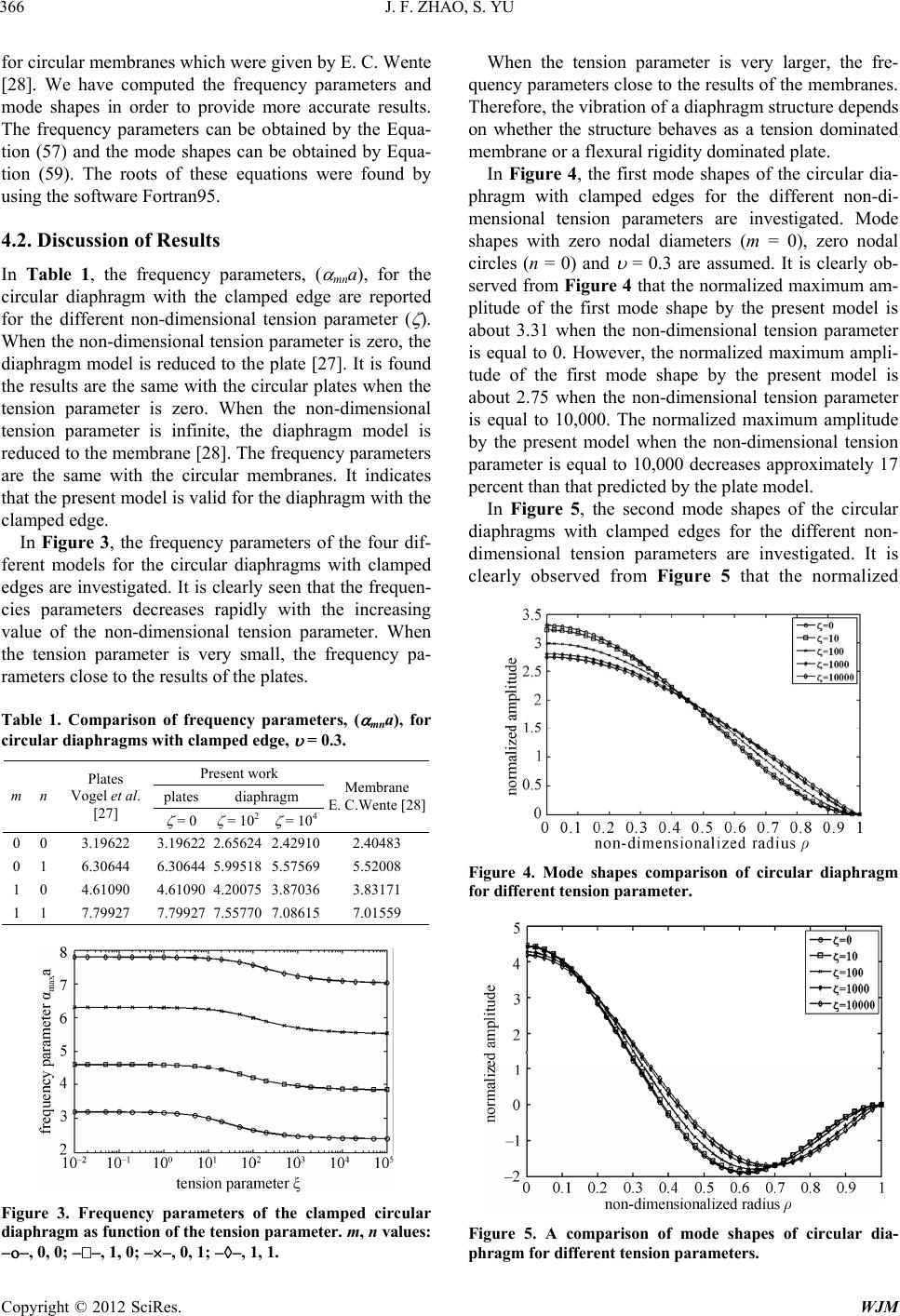 J. F. ZHAO, S. YU Copyright © 2012 SciRes. WJM 366 for circular membranes which were given by E. C. Wente [28]. We have computed the frequency parameters and mode shapes in order to provide more accurate results. The frequency parameters can be obtained by the Equa- tion (57) and the mode shapes can be obtained by Equa- tion (59). The roots of these equations were found by using the software Fortran95. 4.2. Discussion of Results In Table 1, the frequency parameters, ( mna), for the circular diaphragm with the clamped edge are reported for the different non-dimensional tension parameter ( ). When the non-dimensional tension parameter is zero, the diaphragm model is reduced to the plate [27]. It is found the results are the same with the circular plates when the tension parameter is zero. When the non-dimensional tension parameter is infinite, the diaphragm model is reduced to the membrane [28]. The frequency parameters are the same with the circular membranes. It indicates that the present model is valid for the diaphragm with the clamped edge. In Figure 3, the frequency parameters of the four dif- ferent models for the circular diaphragms with clamped edges are investigated. It is clearly seen that the frequen- cies parameters decreases rapidly with the increasing value of the non-dimensional tension parameter. When the tension parameter is very small, the frequency pa- rameters close to the results of the plates. Table 1. Comparison of frequency parameters, ( mna), for circular diaphragms with clamped edge, = 0.3. Present work plates diaphragm m n Plates Vogel et al. [27] = 0 = 102 = 104 Membrane E. C.Wente [28] 0 0 3.19622 3.19622 2.65624 2.42910 2.40483 0 1 6.30644 6.30644 5.99518 5.57569 5.52008 1 0 4.61090 4.61090 4.20075 3.87036 3.83171 1 1 7.79927 7.79927 7.55770 7.08615 7.01559 Figure 3. Frequency parameters of the clamped circular diaphragm as f unction of the t ension par ameter . m, n values: , 0, 0; , 1, 0; , 0, 1; , 1, 1. When the tension parameter is very larger, the fre- quency parameters close to the results of the membranes. Therefore, the vibration of a diaphragm structure depends on whether the structure behaves as a tension dominated membrane or a flexural rigidity dominated plate. In Figure 4, the first mode shapes of the circular dia- phragm with clamped edges for the different non-di- mensional tension parameters are investigated. Mode shapes with zero nodal diameters (m = 0), zero nodal circles (n = 0) and = 0.3 are assumed. It is clearly ob- served from Figure 4 that the normalized maximum am- plitude of the first mode shape by the present model is about 3.31 when the non-dimensional tension parameter is equal to 0. However, the normalized maximum ampli- tude of the first mode shape by the present model is about 2.75 when the non-dimensional tension parameter is equal to 10,000. The normalized maximum amplitude by the present model when the non-dimensional tension parameter is equal to 10,000 decreases approximately 17 percent than that predicted by the plate model. In Figure 5, the second mode shapes of the circular diaphragms with clamped edges for the different non- dimensional tension parameters are investigated. It is clearly observed from Figure 5 that the normalized Figure 4. Mode shapes comparison of circular diaphragm for different tension parameter. Figure 5. A comparison of mode shapes of circular dia- phragm for different tens ion parameters. 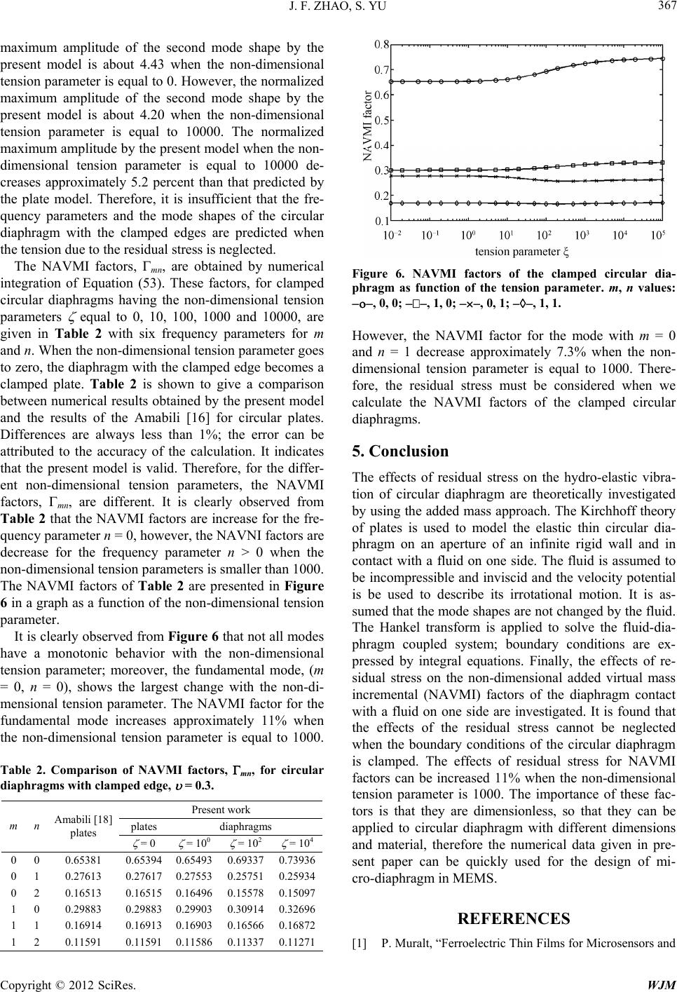 J. F. ZHAO, S. YU Copyright © 2012 SciRes. WJM 367 maximum amplitude of the second mode shape by the present model is about 4.43 when the non-dimensional tension parameter is equal to 0. However, the normalized maximum amplitude of the second mode shape by the present model is about 4.20 when the non-dimensional tension parameter is equal to 10000. The normalized maximum amplitude by the present model when the non- dimensional tension parameter is equal to 10000 de- creases approximately 5.2 percent than that predicted by the plate model. Therefore, it is insufficient that the fre- quency parameters and the mode shapes of the circular diaphragm with the clamped edges are predicted when the tension due to the residual stress is neglected. The NAVMI factors, mn, are obtained by numerical integration of Equation (53). These factors, for clamped circular diaphragms having the non-dimensional tension parameters equal to 0, 10, 100, 1000 and 10000, are given in Table 2 with six frequency parameters for m and n. When the non-dimensional tension parameter goes to zero, the diaphragm with the clamped edge becomes a clamped plate. Table 2 is shown to give a comparison between numerical results obtained by the present model and the results of the Amabili [16] for circular plates. Differences are always less than 1%; the error can be attributed to the accuracy of the calculation. It indicates that the present model is valid. Therefore, for the differ- ent non-dimensional tension parameters, the NAVMI factors, mn, are different. It is clearly observed from Table 2 that the NAVMI factors are increase for the fre- quency parameter n = 0, however, the NAVNI factors are decrease for the frequency parameter n > 0 when the non-dimensional tension parameters is smaller than 1000. The NAVMI factors of Table 2 are presented in Figure 6 in a graph as a function of the non-dimensional tension parameter. It is clearly observed from Figure 6 that not all modes have a monotonic behavior with the non-dimensional tension parameter; moreover, the fundamental mode, (m = 0, n = 0), shows the largest change with the non-di- mensional tension parameter. The NAVMI factor for the fundamental mode increases approximately 11% when the non-dimensional tension parameter is equal to 1000. Table 2. Comparison of NAVMI factors, mn, for circular diaphragms with clampe d e dge, = 0.3. Present work plates diaphragms m n Amabili [18] plates = 0 = 100 = 102 = 104 0 0 0.65381 0.65394 0.65493 0.69337 0.73936 0 1 0.27613 0.27617 0.27553 0.25751 0.25934 0 2 0.16513 0.16515 0.16496 0.15578 0.15097 1 0 0.29883 0.29883 0.29903 0.30914 0.32696 1 1 0.16914 0.16913 0.16903 0.16566 0.16872 1 2 0.11591 0.11591 0.11586 0.11337 0.11271 Figure 6. NAVMI factors of the clamped circular dia- phragm as function of the tension parameter. m, n values: , 0, 0; , 1, 0; , 0, 1; , 1, 1. However, the NAVMI factor for the mode with m = 0 and n = 1 decrease approximately 7.3% when the non- dimensional tension parameter is equal to 1000. There- fore, the residual stress must be considered when we calculate the NAVMI factors of the clamped circular diaphragms. 5. Conclusion The effects of residual stress on the hydro-elastic vibra- tion of circular diaphragm are theoretically investigated by using the added mass approach. The Kirchhoff theory of plates is used to model the elastic thin circular dia- phragm on an aperture of an infinite rigid wall and in contact with a fluid on one side. The fluid is assumed to be incompressible and inviscid and the velocity potential is be used to describe its irrotational motion. It is as- sumed that the mode shapes are not changed by the fluid. The Hankel transform is applied to solve the fluid-dia- phragm coupled system; boundary conditions are ex- pressed by integral equations. Finally, the effects of re- sidual stress on the non-dimensional added virtual mass incremental (NAVMI) factors of the diaphragm contact with a fluid on one side are investigated. It is found that the effects of the residual stress cannot be neglected when the boundary conditions of the circular diaphragm is clamped. The effects of residual stress for NAVMI factors can be increased 11% when the non-dimensional tension parameter is 1000. The importance of these fac- tors is that they are dimensionless, so that they can be applied to circular diaphragm with different dimensions and material, therefore the numerical data given in pre- sent paper can be quickly used for the design of mi- cro-diaphragm in MEMS. REFERENCES [1] P. Muralt, “Ferroelectric Thin Films for Microsensors and 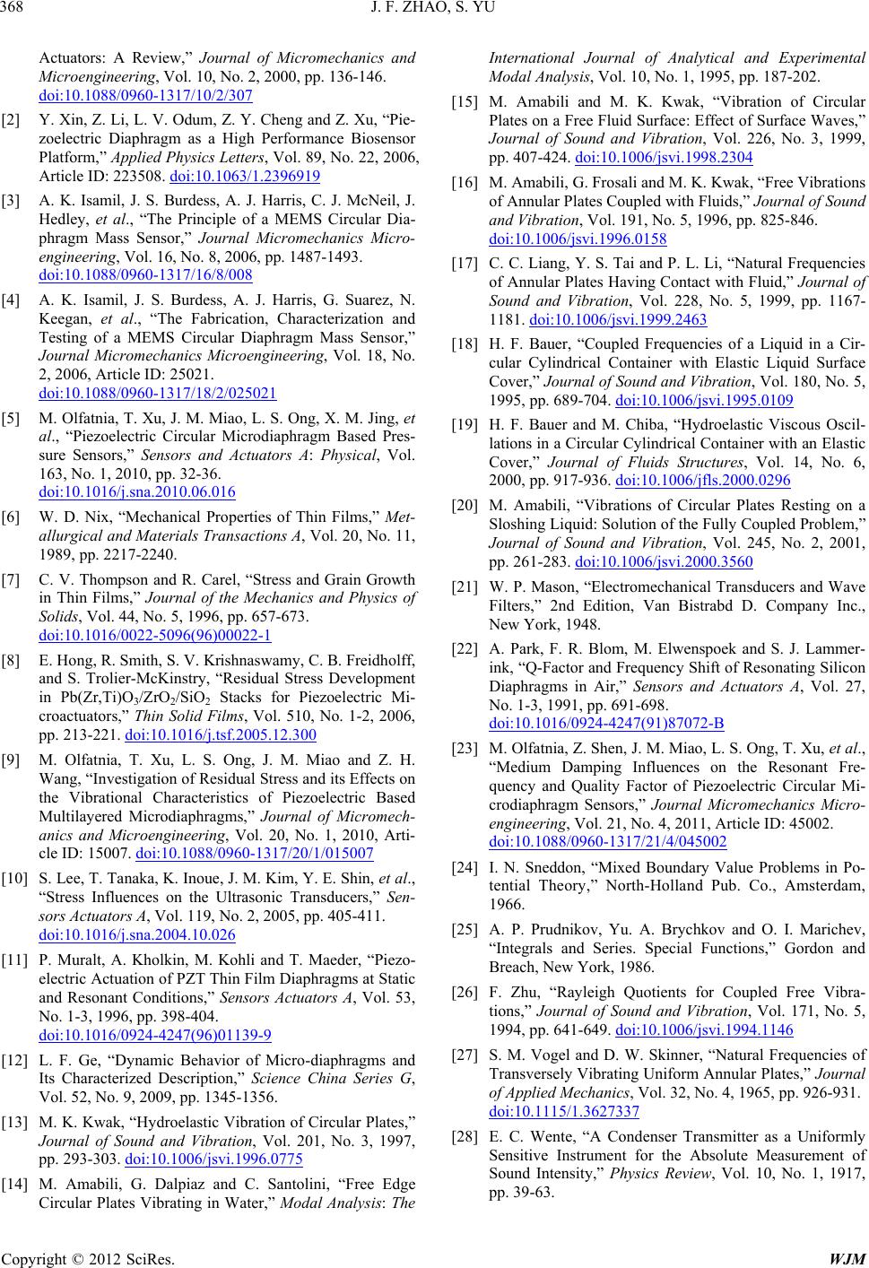 J. F. ZHAO, S. YU Copyright © 2012 SciRes. WJM 368 Actuators: A Review,” Journal of Micromechanics and Microengineering, Vol. 10, No. 2, 2000, pp. 136-146. doi:10.1088/0960-1317/10/2/307 [2] Y. Xin, Z. Li, L. V. Odum, Z. Y. Cheng and Z. Xu, “Pie- zoelectric Diaphragm as a High Performance Biosensor Platform,” Applied Physics Letters, Vol. 89, No. 22, 2006, Article ID: 223508. doi:10.1063/1.2396919 [3] A. K. Isamil, J. S. Burdess, A. J. Harris, C. J. McNeil, J. Hedley, et al., “The Principle of a MEMS Circular Dia- phragm Mass Sensor,” Journal Micromechanics Micro- engineering, Vol. 16, No. 8, 2006, pp. 1487-1493. doi:10.1088/0960-1317/16/8/008 [4] A. K. Isamil, J. S. Burdess, A. J. Harris, G. Suarez, N. Keegan, et al., “The Fabrication, Characterization and Testing of a MEMS Circular Diaphragm Mass Sensor,” Journal Micromechanics Microengineering, Vol. 18, No. 2, 2006, Article ID: 25021. doi:10.1088/0960-1317/18/2/025021 [5] M. Olfatnia, T. Xu, J. M. Miao, L. S. Ong, X. M. Jing, et al., “Piezoelectric Circular Microdiaphragm Based Pres- sure Sensors,” Sensors and Actuators A: Physical, Vol. 163, No. 1, 2010, pp. 32-36. doi:10.1016/j.sna.2010.06.016 [6] W. D. Nix, “Mechanical Properties of Thin Films,” Met- allurgical and Materials Transactions A, Vol. 20, No. 11, 1989, pp. 2217-2240. [7] C. V. Thompson and R. Carel, “Stress and Grain Growth in Thin Films,” Journal of the Mechanics and Physics of Solids, Vol. 44, No. 5, 1996, pp. 657-673. doi:10.1016/0022-5096(96)00022-1 [8] E. Hong, R. Smith, S. V. Krishnaswamy, C. B. Freidholff, and S. Trolier-McKinstry, “Residual Stress Development in Pb(Zr,Ti)O3/ZrO2/SiO2 Stacks for Piezoelectric Mi- croactuators,” Thin Solid Films, Vol. 510, No. 1-2, 2006, pp. 213-221. doi:10.1016/j.tsf.2005.12.300 [9] M. Olfatnia, T. Xu, L. S. Ong, J. M. Miao and Z. H. Wang, “Investigation of Residual Stress and its Effects on the Vibrational Characteristics of Piezoelectric Based Multilayered Microdiaphragms,” Journal of Micromech- anics and Microengineering, Vol. 20, No. 1, 2010, Arti- cle ID: 15007. doi:10.1088/0960-1317/20/1/015007 [10] S. Lee, T. Tanaka, K. Inoue, J. M. Kim, Y. E. Shin, et al., “Stress Influences on the Ultrasonic Transducers,” Sen- sors Actuators A, Vol. 119, No. 2, 2005, pp. 405-411. doi:10.1016/j.sna.2004.10.026 [11] P. Muralt, A. Kholkin, M. Kohli and T. Maeder, “Piezo- electric Actuation of PZT Thin Film Diaphragms at Static and Resonant Conditions,” Sensors Actuators A, Vol. 53, No. 1-3, 1996, pp. 398-404. doi:10.1016/0924-4247(96)01139-9 [12] L. F. Ge, “Dynamic Behavior of Micro-diaphragms and Its Characterized Description,” Science China Series G, Vol. 52, No. 9, 2009, pp. 1345-1356. [13] M. K. Kwak, “Hydroelastic Vibration of Circular Plates,” Journal of Sound and Vibration, Vol. 201, No. 3, 1997, pp. 293-303. doi:10.1006/jsvi.1996.0775 [14] M. Amabili, G. Dalpiaz and C. Santolini, “Free Edge Circular Plates Vibrating in Water,” Modal Analysis: The International Journal of Analytical and Experimental Modal Analysis, Vol. 10, No. 1, 1995, pp. 187-202. [15] M. Amabili and M. K. Kwak, “Vibration of Circular Plates on a Free Fluid Surface: Effect of Surface Waves,” Journal of Sound and Vibration, Vol. 226, No. 3, 1999, pp. 407-424. doi:10.1006/jsvi.1998.2304 [16] M. Amabili, G. Frosali and M. K. Kwak, “Free Vibrations of Annular Plates Coupled with Fluids,” Journal of Sound and Vibration, Vol. 191, No. 5, 1996, pp. 825-846. doi:10.1006/jsvi.1996.0158 [17] C. C. Liang, Y. S. Tai and P. L. Li, “Natural Frequencies of Annular Plates Having Contact with Fluid,” Journal of Sound and Vibration, Vol. 228, No. 5, 1999, pp. 1167- 1181. doi:10.1006/jsvi.1999.2463 [18] H. F. Bauer, “Coupled Frequencies of a Liquid in a Cir- cular Cylindrical Container with Elastic Liquid Surface Cover,” Journal of Sound and Vibration, Vol. 180, No. 5, 1995, pp. 689-704. doi:10.1006/jsvi.1995.0109 [19] H. F. Bauer and M. Chiba, “Hydroelastic Viscous Oscil- lations in a Circular Cylindrical Container with an Elastic Cover,” Journal of Fluids Structures, Vol. 14, No. 6, 2000, pp. 917-936. doi:10.1006/jfls.2000.0296 [20] M. Amabili, “Vibrations of Circular Plates Resting on a Sloshing Liquid: Solution of the Fully Coupled Problem,” Journal of Sound and Vibration, Vol. 245, No. 2, 2001, pp. 261-283. doi:10.1006/jsvi.2000.3560 [21] W. P. Mason, “Electromechanical Transducers and Wave Filters,” 2nd Edition, Van Bistrabd D. Company Inc., New York, 1948. [22] A. Park, F. R. Blom, M. Elwenspoek and S. J. Lammer- ink, “Q-Factor and Frequency Shift of Resonating Silicon Diaphragms in Air,” Sensors and Actuators A, Vol. 27, No. 1-3, 1991, pp. 691-698. doi:10.1016/0924-4247(91)87072-B [23] M. Olfatnia, Z. Shen, J. M. Miao, L. S. Ong, T. Xu, et al., “Medium Damping Influences on the Resonant Fre- quency and Quality Factor of Piezoelectric Circular Mi- crodiaphragm Sensors,” Journal Micromechanics Micro- engineering, Vol. 21, No. 4, 2011, Article ID: 45002. doi:10.1088/0960-1317/21/4/045002 [24] I. N. Sneddon, “Mixed Boundary Value Problems in Po- tential Theory,” North-Holland Pub. Co., Amsterdam, 1966. [25] A. P. Prudnikov, Yu. A. Brychkov and O. I. Marichev, “Integrals and Series. Special Functions,” Gordon and Breach, New York, 1986. [26] F. Zhu, “Rayleigh Quotients for Coupled Free Vibra- tions,” Journal of Sound and Vibration, Vol. 171, No. 5, 1994, pp. 641-649. doi:10.1006/jsvi.1994.1146 [27] S. M. Vogel and D. W. Skinner, “Natural Frequencies of Transversely Vibrating Uniform Annular Plates,” Journal of Applied Mechanics, Vol. 32, No. 4, 1965, pp. 926-931. doi:10.1115/1.3627337 [28] E. C. Wente, “A Condenser Transmitter as a Uniformly Sensitive Instrument for the Absolute Measurement of Sound Intensity,” Physics Review, Vol. 10, No. 1, 1917, pp. 39-63. |