

Paper Menu >>
Journal Menu >>
 Journal of Modern Physics, 2012, 3, 1991-1997 http://dx.doi.org/10.4236/jmp.2012.312249 Published Online December 2012 (http://www.SciRP.org/journal/jmp) Influence of a Static Magnetic Field on Beam Emittance in Laser Wakefield Acceleration Mathieu Drouin, Alain Bourdier, Quentin Harry, Sébastien Rassou CEA, DAM, DIF, Arpajon, France Email: [email protected] Received September 19, 2012; revised November 2, 2012; accepted November 10, 2012 ABSTRACT The enhancement of trapping and the optimization of beam quality are two key issues of Laser Wakefield Acceleration (LWFA). The effect of a homogenous constant magnetic field B0, parallel to the direction of propagation of the pump pulse, is studied in the blowout regime via 2Dx3Dv Particle-In-Cell simulations. Electrons are injected into the wake using a counter-propagating low amplitude laser. Transverse currents are generated at the rim of the bubble, which re- sults in the amplification of the B0 field at the rear of the bubble. Therefore the dynamics of the beam is modified, the main effect is the reduction of the transverse emittance when B0 is raised. Depending on beam loading effects the low energy tail, observed in the non-magnetized case, can be suppressed when B0 is applied, which provides a mono-ener- getic beam. Keywords: Laser Wakefield Acceleration; Magnetic Field; Beam Emittance; Beam Loading 1. Introduction In Laser Wake-Field Acceleration (LWFA) [1-4], a laser creates a plasma wave wakefield with a phase velocity close to the speed of light (c). The acceleration gradi- ents in these wakefields can easily exceed 100 GeV/m, hence a cm-long plasma based accelerator can produce- GeV-energy electron beams. An electron injected in such a wave gains energy from the longitudinal component of the electric field, as long as the pump pulse is not de- pleted and the dephasing length is not reached. These wakefields have ideal properties for accelerating elec- trons. The transverse focusing field increases linearly with the radial distance and the accelerating longitudinal field is independent of the radial coordinate [5,6]. LWFA can be split into different options. The first corresponds to a plasma density e, a pulse length (cτ) matching half of a plasma period and a spot size (w0) 19 3 n 10 cm roughly equals to the bubble radius, 00 wac 21 2 W cm 19 2 10W cmI 18 3 10 cmn and plasma density e according to the guidelines proposed by Lu et al. [11] to achieve a more controlled and stable blowout of the elec- trons, with no self-injection. In order to limit the computa- tional requirements of our PIC (Particle-In-Cell) simula- tions the propagation of the pump pulse will not exceed 1 cm, moreover we restrict our study to 2Dx3Dv (two- di- mensional space and three-dimensional velocity). We fo- cus on wakefield acceleration in the presence of an exter- nal, initially homogenous, magnetic field and we study its influence through PIC simulations. In the first part of this paper, we will give the simulation setup and we will spec- ify how the plasma is magnetized. Then, in the second part, the main findings induced by the magnetic field will be detailed. Attention will be paid to self-consistent amplifi- cation of the magnetic field at the rear of the bubble. The emittance of the accelerated beam will be compared with or without B0 field. In the third part, the influence of the magnetic field on the energy distribution of the beam will be briefly commented. Lastly we will draw some conclusions. , where a0 is the normalized vector potential of the laser. This is the idea of the bubble regime [7,8]. For these conditions, a hundred-joule class laser would have an intensity of the order ~10 . In this regime, the electrons are continuously injected, this results in tre- mendous beam loading and the loaded wake is noisy. In this paper electron injection is achieved using the collid- ing pulse scheme [9,10], hence the bubble regime is not appropriate. We rather select moderate laser intensity 2. Simulation Setup The effect of a strong external magnetic field has seldom been reported in the context of wakefield acceleration. Let us first summarize some recent papers. It was first proposed in the context of LWFA by Hur et al. [12], with a single pump laser a0 = 3.5 and an electronic density ne = 3 × 10⁻³ nc, where nc is the critical density. This setup is C opyright © 2012 SciRes. JMP 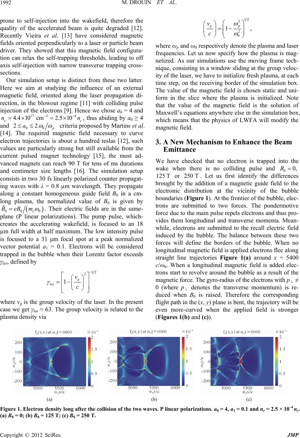 M. DROUIN ET AL. 1992 prone to self-injection into the wakefield, therefore the quality of the accelerated beam is quite degraded [12]. Recently Vieira et al. [13] have considered magnetic fields oriented perpendicularly to a laser or particle beam driver. They showed that this magnetic field configura- tion can relax the self-trapping thresholds, leading to off axis self-injection with narrow transverse trapping cross- sections. 12 2 0 2 1 gp c v 0,B Our simulation setup is distinct from these two latter. Here we aim at studying the influence of an external magnetic field, oriented along the laser propagation di- rection, in the blowout regime [11] with colliding pulse injection of the electrons [9]. Hence we chose a0 = 4 and ec , thus abiding by a0 ≥ 4 and 17 3 4.4 10cm 4 2.5 10nn 00p 22a criteria proposed by Martins et al. [14]. The required magnetic field necessary to curve electron trajectories is about a hundred teslas [12], such values are particularly strong but still available from the current pulsed magnet technology [15], the most ad- vanced magnets can reach 90 T for tens of ms durations and centimeter size lengths [16]. The simulation setup consists in two 30 fs linearly polarized counter propagat- ing waves with λ = 0.8 µm wavelength. They propagate along a constant homogeneous guide field B0 in a cm- long plasma, the normalized value of B0 is given by 00 0e BeBm . Their electric fields are in the same- plane (P linear polarizations). The pump pulse, which- creates the accelerating wakefield, is focused to an 18 µm full width at half maximum. The low intensity pulse is focused to a 31 μm focal spot at a peak normalized vector potential a1 = 0.1. Electrons will be considered trapped in the bubble when their Lorentz factor exceeds γlas, defined by 12 2 1g v c las where vg is the group velocity of the laser. In the present case we get γlas ≈ 63. The group velocity is related to the plasma density via , where ωp and ω0 respectively denote the plasma and laser frequencies. Let us now specify how the plasma is mag- netized. As our simulations use the moving frame tech- nique, consisting in a window sliding at the group veloc- ity of the laser, we have to initialize fresh plasma, at each time step, on the receiving border of the simulation box. The value of the magnetic field is chosen static and uni- form in the slice where the plasma is initialized. Note that the value of the magnetic field is the solution of Maxwell’s equations anywhere else in the simulation box, which means that the physics of LWFA will modify the magnetic field. 3. A New Mechanism to Enhance the Beam Emittance We have checked that no electron is trapped into the wake when there is no colliding pulse and 0 or . Let us first identify the differences brought by the addition of a magnetic guide field to the electronic distribution at the vicinity of the bubble boundaries (Figure 1). At the frontier of the bubble, elec- trons are submitted to two forces. The pondermotive force due to the main pulse repels electrons and thus pro- vides them longitudinal and transverse momenta. Mean- while, electrons are submitted to the recall electric field induced by the bubble. The balance between these two forces will define the borders of the bubble. When no longitudinal magnetic field is applied electrons flee along straight line trajectories Figure 1(a) around x = 5400 c/ω0. When a longitudinal magnetic field is added elec- trons start to revolve around the bubble as a result of the magnetic force. The gyro-radius of the electrons with p⊥ ≠ 0 (where p⊥ denotes the transverse momentum) is re- duced when B0 is raised. Therefore the corresponding flight path in the (x, y) plane is bent, the trajectory will be even more-curved when the applied field is stronger (Figures 1(b) and (c)). 125 T250 T (a) (b) (c) Figure 1. Electron density long after the collision of the two waves. P linear polarizations. a0 = 4, a1 = 0.1 and ne = 2.5 × 10⁻⁴ nc. a) B0 = 0; (b) B0 = 125 T; (c) B0 = 250 T. ( Copyright © 2012 SciRes. JMP  M. DROUIN ET AL. 1993 3.1. Self-Consistent Amplification of the Magnetic Field When electrons revolve around the bubble they create a current (denoted by Jz) perpendicularly to the plane of the figure, as evidenced by Figure 2. We get a map of the transverse velocity vz when dividing Jz by the elec- tronic density ne, electrons revolving around the bottle neck of the bubble have velocities in the range 0.5 ≤ vz/c ≤ 0.8. This current will act as a small solenoid, and thus the longitudinal magnetic field will be amplified. The intensity of the magnetic field is almost doubled- locally (Figure 3) compared to the initial (t = 0) uni- form map of Bx. We shall underline that this pattern is stable as we obtain quasi identical maps of Bx in this re- gion of the bubble when the pump pulse has just en- tered the plasma around ω0t = 2280. Moreover we note that the geometry of the magnetic field lines is weakly al- tered by the electronic density modulations induced by the propagating bubble. Magnetic field lines stay almost parallel to the propagation direction. 3.2. A Way to Enhance the Beam Emittance Let us now examine the effect of the magnetic field on the dynamics of the accelerated beam. The emittance of the trapped beam (i.e. particles with γ > γlas), defined by 2 22 ,1 nrmsey y mcy pyp , was computed ac- cording to Equations (11) and (12) of [17]. The emittance (a) (b) Figure 2. Transverse component of the current density (normalized by encc), the wakefield propagates in a magnetized plasma (B0 = 250 T). a0 = 4, a1 = 0.1 and ne = 2.5 × 10⁻⁴ nc. Figure 3. Longitudinal component of the magnetic field (in Teslas), the wakefield propagates in a magnetized plasma B0 = 250 . a0 = 4, a1 = 0.1 and ne = 2.5 × 10⁻⁴ nc. Magnetic field lines are superimposed (red curves) on Bx color map. T Copyright © 2012 SciRes. JMP  M. DROUIN ET AL. 1994 plot (Figure 4) clearly distinguishes B0 = 0, B0 = 125 T cases from the highly magnetized case B0 = 250 T. In the first category, the emittance slowly grows during the propagation and has a pseudo-periodic oscillation. In the second category, the beam emittance is almost constant during the whole acceleration, and the final value of the beam emittance εn,rms ~ 0.56 π mm mrad is 14 times weaker than in the unmagnetized case! To get more in- formation we have plotted kinetic energy density maps showing the evolution of the trapped beam at the rear of the bubble for both the magnetized and the unmagnetized regimes. In the unmagnetized case (Figure 5), we clearly observe betatron oscillations due to the finite initial ra- dial momentum of injected electrons. Betatron frequency is given by 12 2 bp 0bb TT , according to this formula the pulsation decreases when the beam accelerates. The normalized period minimum value is given by 12 2π 2las 1 0 ~2200T 0,max 0 2π b p b T , with γlas ≈ 63 and ne,beam ~ 10–3 nc we get b . This result is in good agreement with Figure 4 when B0 = 0. The dynamics is completely different in the magnetized Figure 4. Normalized transverse emittance nrmsy y e yp yp mc 2 22 , 1, in units π mm mrad. Black, green and red curves respectively correspond to B0 = 0, B0 = 125 T and B0 = 250 T. a0 = 4, a1 = 0.1 and ne = 2.5 × 10⁻⁴ nc. Figure 5. Electron kinetic energy density (normalized by mec2nc), the wakefield propagates in a non magnetized plasma (B0 = ). a0 = 4, a1 = 0.1 and ne = 2.5 × 10⁻⁴ nc. 0 Copyright © 2012 SciRes. JMP 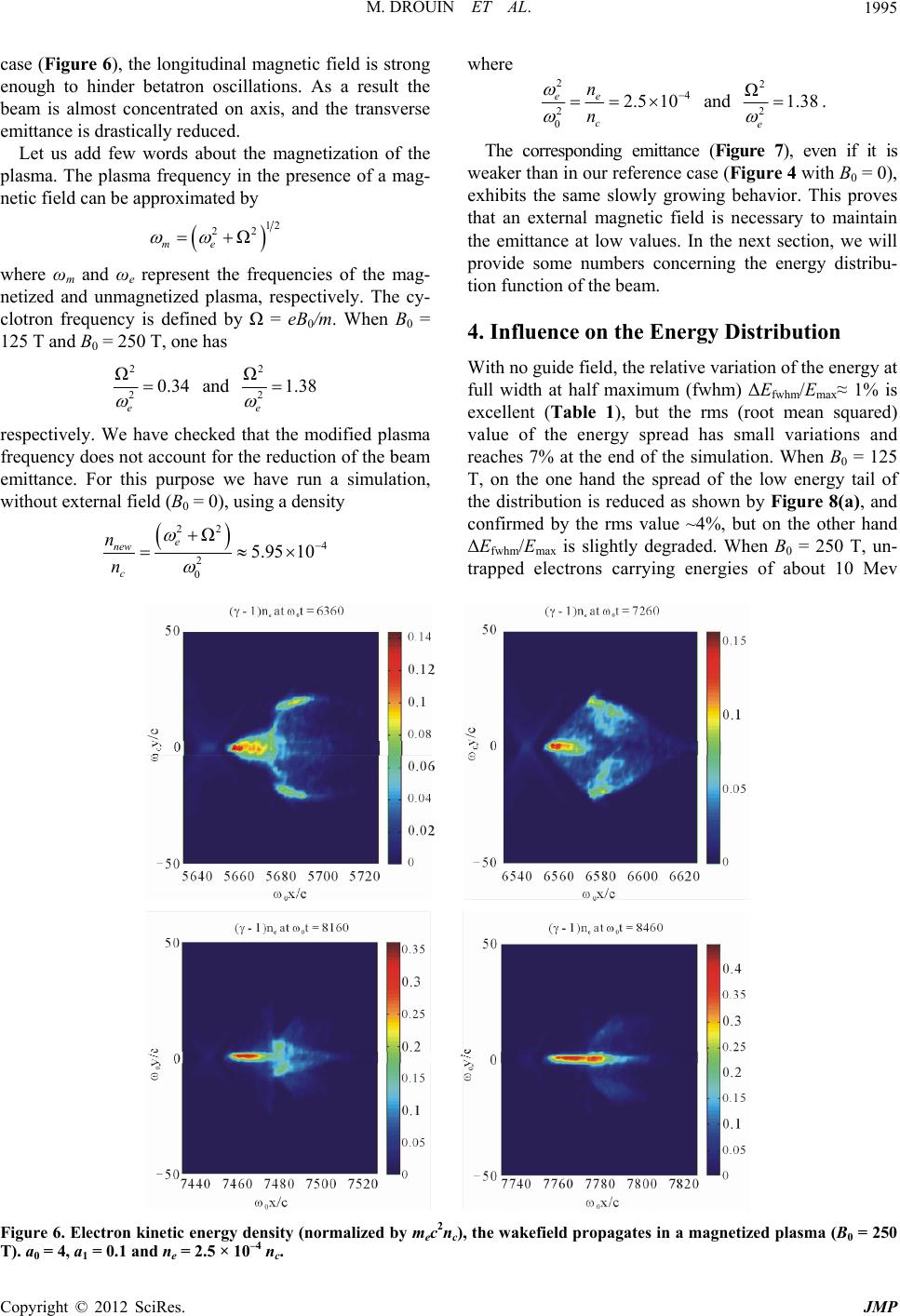 M. DROUIN ET AL. 1995 case (Figure 6), the longitudinal magnetic field is strong enough to hinder betatron oscillations. As a result the beam is almost concentrated on axis, and the transverse emittance is drastically reduced. Let us add few words about the magnetization of the plasma. The plasma frequency in the presence of a mag- netic field can be approximated by 212 2 Ω me where ωm and ωe represent the frequencies of the mag- netized and unmagnetized plasma, respectively. The cy- clotron frequency is defined by Ω = eB0/m. When B0 = 125 T and B0 = 250 T, one has 2 20.34 e Ω and 2 2 Ω1.38 e respectively. We have checked that the modified plasma frequency does not account for the reduction of the beam emittance. For this purpose we have run a simulation, without external field (B0 = 0), using a density 22 2 0 Ω e new c n n where 4 5.95 10 2 4 2 0 2.5 10 ee c n n and 2 2 Ω1.38 e . The corresponding emittance (Figure 7), even if it is weaker than in our reference case (Figure 4 with B0 = 0), exhibits the same slowly growing behavior. This proves that an external magnetic field is necessary to maintain the emittance at low values. In the next section, we will provide some numbers concerning the energy distribu- tion function of the beam. 4. Influence on the Energy Distribution With no guide field, the relative variation of the energy at full width at half maximum (fwhm) ΔEfwhm/Emax≈ 1% is excellent (Table 1), but the rms (root mean squared) value of the energy spread has small variations and reaches 7% at the end of the simulation. When B0 = 125 T, on the one hand the spread of the low energy tail of the distribution is reduced as shown by Figure 8(a), and confirmed by the rms value ~4%, but on the other hand ΔEfwhm/Emax is slightly degraded. When B0 = 250 T, un- trapped electrons carrying energies of about 10 Mev Figure 6. Electron kinetic energy density (normalized by mec2nc), the wakefield propagates in a magnetized plasma (B0 = 250 ). a0 = 4, a1 = 0.1 and ne = 2.5 × 10⁻⁴ nc. T Copyright © 2012 SciRes. JMP 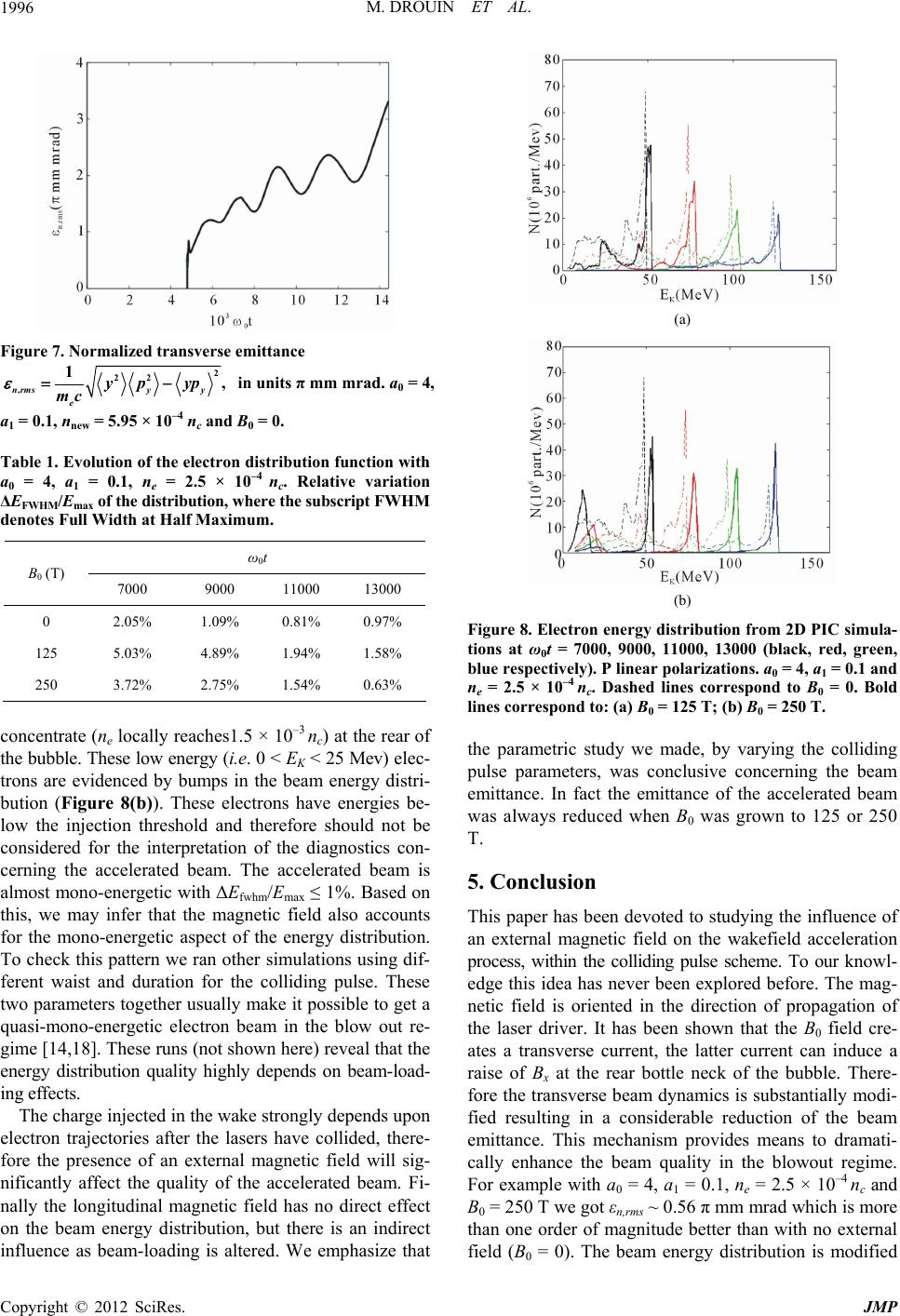 M. DROUIN ET AL. 1996 Figure 7. Normalized transverse emittance nrms e mc , 1 y y yp yp 2 22 , in units π mm mrad. a0 = 4, a1 = 0.1, nnew = 5.95 × 10⁻⁴ nc and B0 = 0. Table 1. Evolution of the electron distribution function with a0 = 4, a1 = 0.1, ne = 2.5 × 10⁻⁴ nc. Relative variation ΔEFWHM/Emax of the distribution, where the subscript FWHM denotes Full Width at Half Maximum. ω0t B0 (T) 7000 9000 11000 13000 0 2.05% 1.09% 0.81% 0.97% 125 5.03% 4.89% 1.94% 1.58% 250 3.72% 2.75% 1.54% 0.63% concentrate (ne locally reaches1.5 × 10–3 nc) at the rear of the bubble. These low energy (i.e. 0 < EK < 25 Mev) elec- trons are evidenced by bumps in the beam energy distri- bution (Figure 8(b)). These electrons have energies be- low the injection threshold and therefore should not be considered for the interpretation of the diagnostics con- cerning the accelerated beam. The accelerated beam is almost mono-energetic with ΔEfwhm/Emax ≤ 1%. Based on this, we may infer that the magnetic field also accounts for the mono-energetic aspect of the energy distribution. To check this pattern we ran other simulations using dif- ferent waist and duration for the colliding pulse. These two parameters together usually make it possible to get a quasi-mono-energetic electron beam in the blow out re- gime [14,18]. These runs (not shown here) reveal that the energy distribution quality highly depends on beam-load- ing effects. The charge injected in the wake strongly depends upon electron trajectories after the lasers have collided, there- fore the presence of an external magnetic field will sig- nificantly affect the quality of the accelerated beam. Fi- nally the longitudinal magnetic field has no direct effect on the beam energy distribution, but there is an indirect influence as beam-loading is altered. We emphasize that (a) (b) Figure 8. Electron energy distribution from 2D PIC simula- tions at ω0t = 7000, 9000, 11000, 13000 (black, red, green, blue respectively). P linear polarizations. a0 = 4, a1 = 0.1 and ne = 2.5 × 10⁻⁴ nc. Dashed lines correspond to B0 = 0. Bold lines correspond to: (a) B0 = 125 T; (b) B0 = 250 T. the parametric study we made, by varying the colliding pulse parameters, was conclusive concerning the beam emittance. In fact the emittance of the accelerated beam was always reduced when B0 was grown to 125 or 250 T. 5. Conclusion This paper has been devoted to studying the influence of an external magnetic field on the wakefield acceleration process, within the colliding pulse scheme. To our knowl- edge this idea has never been explored before. The mag- netic field is oriented in the direction of propagation of the laser driver. It has been shown that the B0 field cre- ates a transverse current, the latter current can induce a raise of Bx at the rear bottle neck of the bubble. There- fore the transverse beam dynamics is substantially modi- fied resulting in a considerable reduction of the beam emittance. This mechanism provides means to dramati- cally enhance the beam quality in the blowout regime. For example with a0 = 4, a1 = 0.1, ne = 2.5 × 10⁻⁴ nc and B0 = 250 T we got εn,rms ~ 0.56 π mm mrad which is more than one order of magnitude better than with no external field (B0 = 0). The beam energy distribution is modified Copyright © 2012 SciRes. JMP 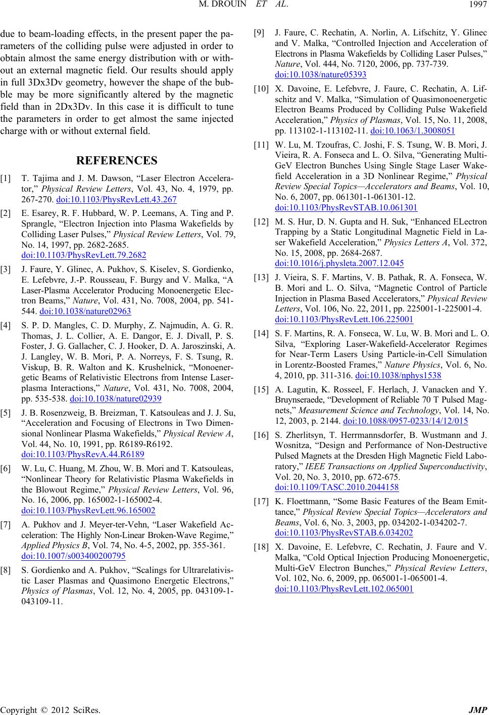 M. DROUIN ET AL. 1997 due to beam-loading effects, in the present paper the pa- rameters of the colliding pulse were adjusted in order to obtain almost the same energy distribution with or with- out an external magnetic field. Our results should apply in full 3Dx3Dv geometry, however the shape of the bub- ble may be more significantly altered by the magnetic field than in 2Dx3Dv. In this case it is difficult to tune the parameters in order to get almost the same injected charge with or without external field. REFERENCES [1] T. Tajima and J. M. Dawson, “Laser Electron Accelera- tor,” Physical Review Letters, Vol. 43, No. 4, 1979, pp. 267-270. doi:10.1103/PhysRevLett.43.267 [2] E. Esarey, R. F. Hubbard, W. P. Leemans, A. Ting and P. Sprangle, “Electron Injection into Plasma Wakefields by Colliding Laser Pulses,” Physical Review Letters, Vol. 79, No. 14, 1997, pp. 2682-2685. doi:10.1103/PhysRevLett.79.2682 [3] J. Faure, Y. Glinec, A. Pukhov, S. Kiselev, S. Gordienko, E. Lefebvre, J.-P. Rousseau, F. Burgy and V. Malka, “A Laser-Plasma Accelerator Producing Monoenergetic Elec- tron Beams,” Nature, Vol. 431, No. 7008, 2004, pp. 541- 544. doi:10.1038/nature02963 [4] S. P. D. Mangles, C. D. Murphy, Z. Najmudin, A. G. R. Thomas, J. L. Collier, A. E. Dangor, E. J. Divall, P. S. Foster, J. G. Gallacher, C. J. Hooker, D. A. Jaroszinski, A. J. Langley, W. B. Mori, P. A. Norreys, F. S. Tsung, R. Viskup, B. R. Walton and K. Krushelnick, “Monoener- getic Beams of Relativistic Electrons from Intense Laser- plasma Interactions,” Nature, Vol. 431, No. 7008, 2004, pp. 535-538. doi:10.1038/nature02939 [5] J. B. Rosenzweig, B. Breizman, T. Katsouleas and J. J. Su, “Acceleration and Focusing of Electrons in Two Dimen- sional Nonlinear Plasma Wakefields,” Physical Review A, Vol. 44, No. 10, 1991, pp. R6189-R6192. doi:10.1103/PhysRevA.44.R6189 [6] W. Lu, C. Huang, M. Zhou, W. B. Mori and T. Katsouleas, “Nonlinear Theory for Relativistic Plasma Wakefields in the Blowout Regime,” Physical Review Letters, Vol. 96, No. 16, 2006, pp. 165002-1-165002-4. doi:10.1103/PhysRevLett.96.165002 [7] A. Pukhov and J. Meyer-ter-Vehn, “Laser Wakefield Ac- celeration: The Highly Non-Linear Broken-Wave Regime,” Applied Physics B, Vol. 74, No. 4-5, 2002, pp. 355-361. doi:10.1007/s003400200795 [8] S. Gordienko and A. Pukhov, “Scalings for Ultrarelativis- tic Laser Plasmas and Quasimono Energetic Electrons,” Physics of Plasmas, Vol. 12, No. 4, 2005, pp. 043109-1- 043109-11. [9] J. Faure, C. Rechatin, A. Norlin, A. Lifschitz, Y. Glinec and V. Malka, “Controlled Injection and Acceleration of Electrons in Plasma Wakefields by Colliding Laser Pulses,” Nature, Vol. 444, No. 7120, 2006, pp. 737-739. doi:10.1038/nature05393 [10] X. Davoine, E. Lefebvre, J. Faure, C. Rechatin, A. Lif- schitz and V. Malka, “Simulation of Quasimonoenergetic Electron Beams Produced by Colliding Pulse Wakefield Acceleration,” Physics of Plasmas, Vol. 15, No. 11, 2008, pp. 113102-1-113102-11. doi:10.1063/1.3008051 [11] W. Lu, M. Tzoufras, C. Joshi, F. S. Tsung, W. B. Mori, J. Vieira, R. A. Fonseca and L. O. Silva, “Generating Multi- GeV Electron Bunches Using Single Stage Laser Wake- field Acceleration in a 3D Nonlinear Regime,” Physical Review Special Topics—Accelerators and Beams, Vol. 10, No. 6, 2007, pp. 061301-1-061301-12. doi:10.1103/PhysRevSTAB.10.061301 [12] M. S. Hur, D. N. Gupta and H. Suk, “Enhanced ELectron Trapping by a Static Longitudinal Magnetic Field in La- ser Wakefield Acceleration,” Physics Letters A, Vol. 372, No. 15, 2008, pp. 2684-2687. doi:10.1016/j.physleta.2007.12.045 [13] J. Vieira, S. F. Martins, V. B. Pathak, R. A. Fonseca, W. B. Mori and L. O. Silva, “Magnetic Control of Particle Injection in Plasma Based Accelerators,” Physical Review Letters, Vol. 106, No. 22, 2011, pp. 225001-1-225001-4. doi:10.1103/PhysRevLett.106.225001 [14] S. F. Martins, R. A. Fonseca, W. Lu, W. B. Mori and L. O. Silva, “Exploring Laser-Wakefield-Accelerator Regimes for Near-Term Lasers Using Particle-in-Cell Simulation in Lorentz-Boosted Frames,” Nature Physics, Vol. 6, No. 4, 2010, pp. 311-316. doi:10.1038/nphys1538 [15] A. Lagutin, K. Rosseel, F. Herlach, J. Vanacken and Y. Bruynseraede, “Development of Reliable 70 T Pulsed Mag- nets,” Measurement Science and Technology, Vol. 14, No. 12, 2003, p. 2144. doi:10.1088/0957-0233/14/12/015 [16] S. Zherlitsyn, T. Herrmannsdorfer, B. Wustmann and J. Wosnitza, “Design and Performance of Non-Destructive Pulsed Magnets at the Dresden High Magnetic Field Labo- ratory,” IEEE Transactions on Applied Superconductivity, Vol. 20, No. 3, 2010, pp. 672-675. doi:10.1109/TASC.2010.2044158 [17] K. Floettmann, “Some Basic Features of the Beam Emit- tance,” Physical Review Special Topics—Accelerators and Beams, Vol. 6, No. 3, 2003, pp. 034202-1-034202-7. doi:10.1103/PhysRevSTAB.6.034202 [18] X. Davoine, E. Lefebvre, C. Rechatin, J. Faure and V. Malka, “Cold Optical Injection Producing Monoenergetic, Multi-GeV Electron Bunches,” Physical Review Letters, Vol. 102, No. 6, 2009, pp. 065001-1-065001-4. doi:10.1103/PhysRevLett.102.065001 Copyright © 2012 SciRes. JMP |