

Paper Menu >>
Journal Menu >>
 Optics and Photonics Journal, 2012, 2, 318-325 http://dx.doi.org/10.4236/opj.2012.24039 Published Online December 2012 (http://www.SciRP.org/journal/opj) Propagation of Modified Bessel-Gaussian Beams in a Misaligned Optical System Lahcen Ez-Zariy1, Hamid Nebdi1, El Hassane Bentefour2, Abdelmajid Belafhal1* 1Laboratoire de Physique Nucléaire, Atomique et Moléculaire Département de Physique, Faculté des Sciences, Université Chouaïb Doukkali, El Jadida, Morocco 2LigthOnKnowledge Foundation, Chicago, USA Email: *[email protected] Received August 15, 2012; revised September 15, 2012; accepted September 30, 2012 ABSTRACT The formalism of generalized diffraction integral for paraxial misaligned optical systems is used to investigate the propagation of the Modified Bessel-Gaussian (MBG) beam through a misaligned thin lens. The properties of the propagation of MBG beam traveling through this misaligned ABCD optical system are discussed. A special case of misaligned circular thin lens is illustrated analytically and numerically. The shape of the MBG beam at the exit of the misaligned optical system is unchanged; however the center of the beam is shifted from the propagation axis in corre- lated manner with the design parameters of the optical system. Keywords: Generalized Diffraction Integral; Modified Bessel-Gaussian Beams; Propagation; Misaligned ABCD Optical Systems; Circular Thin Lens 1. Introduction Modified optical beams, such as zero central intensity beams and vortex beams, gained increasing importance in the recent years [1,2]. Among their applications are the guiding and manipulating of particle beam such as in atoms interferometry, atoms trapping and cooling, and in wireless Tera-bite-speed information transport. Particular attention is given to the propagation of Bessel and Modi- fied Bessel beams, which their apodization by a Gaussian transmittance leads to the so called, in literature, Modi- fied Bessel-Gaussian beams (referred in the follows as MBG beams). Several studies have examined the propagation of MBG beams through a turbulent atmosphere [3,4], and through aligned optical systems [5-11]. These studies and others [12-21] intend to comprehend practical matters such as the impact of imperfections in the optical systems on the propagation of the MBG beams. Such imperfec- tions, which translate into misalignment of the optical systems, may be due in one hand to the design and manufacturing mishaps and in other hand due to external perturbations such as thermally induced deformations and or the accumulation of dust and fingerprints, etc. In this perspective, the propagation of nondiffracting and pseudo-nondiffracting Laser beams through misaligned optical systems is of great interest. Recently, Zhao et al. [17] have used the generalized diffraction integral to derive a generalized formula for high-order Bessel-Gaussian beams through a misaligned first order ABCD optical system. In 2009, Chafiq et al. [19] have applied the generalized diffraction integral to develop an analytical formalism for generalized Mathieu- Gauss beams passing through an aperture misaligned optical system. Moreover, in a recent work, Belafhal et al. [20] have studied the propagation of truncated Bessel modulated Gaussian (QBG) beams traveling any mis- aligned ABCD optical system using the generalized dif- fraction integral formalism. To our knowledge, the propagation of MBG beams through misaligned optical systems has not been studied yet. In this paper, we use the generalized diffraction in- tegral introduced by Wang and Ronchi [22], and all our previous work, in this field, to develop the analytical solution of the propagation of MBG beams traveling through any misaligned optical system. For illustration, we apply our solution to the particular case of the propa- gation of MBG beams through a misaligned lens. More interestingly, we demonstrate that our analytical result is a generated formalism which allows for retrieving the solution of the propagation of pure Bessel, Gaussian and of Bessel-Gaussian beams through a misaligned optical system [17] as particular cases. The paper is organized as follows: in Section 2, we calculate the analytical equation of MBG beams passing *Corresponding author. C opyright © 2012 SciRes. OPJ  L. EZ-ZARIY ET AL. 319 through any misaligned optical system ABCD. Then, from this equation, we derive the solutions for the special cases of the Bessel, Gaussian and Bessel-Gaussian beams propagating through the same optical system. In Section 3, we use the main expression of Section 2 to perform detailed analysis of the propagation of MBG through a misaligned thin lens analytically and numerically. 2. Propagation of MBG Beams through Misaligned Paraxial Optical System MBG beams are solutions of the 3D Helmholtz equation in cylindrical coordinates. These beams are the general- ized Modified Bessel beams modulated by Gaussian transmittance. The field distribution of MBG beams in the source plane situated at z = 0 is composed by the product of a Gaussian function part and a summation over the modified Bessel functions of different ampli- tudes An. This field is expressed by [11] 00 2 00 ,,0 expexp i, N nn n Er krAn Iar 0B (1) where n denotes the order of modified Bessel function In, aB is the width parameter, 2π k is the wave number with being the wavelength, 2 1i 2 s s F k , where s and s F respectively refer to radial Gaussian source and focusing parameter, i1. In Figure 1, we present the plots of the incident single and multiple MBG beams intensity at different orders and with various amplitude coefficients. Figure 1(a) shows a single modified Bessel-Gaussian beam of order 10 which can be obtained from summation in Equation (1) by setting n = N = 10. The diagram of the considered figure shows the single modified Bessel beam of order 10 which is a doughnut beam (this observation holds true for any single beam of order n > 0). Figure 1(b) displays an example of a superposition of the modified Bessel- Gaussian beams for different odd orders, n, and with various amplitudes, An. From this figure, it appears that the beam is a dark hollow beam, and the plot presents two principal lobes surrounded by secondary lobes. In addition, we note that the considered figure presents a (a) (b) Figure 1. Normalized transverse irradiance distributions of input single and multiple MBG beams at various amplitude s: (a) ; (b) 10 10 n nA 1357 10.50.21 n nA . Copyright © 2012 SciRes. OPJ  L. EZ-ZARIY ET AL. 320 y O z z Misaligned MBG beam Input plane Output plane x Input MBG beam ε y ε y ε x ε z m RP 2 RP 1 RP 1 m RP 2 m A B CD O 2 m ε εʹ Figure 2. Schematic representation of MBG beams propagation trough a misaligned paraxial ABCD optical system. symmetry in the lobes, because the products of generate terms defining the azi- muthal intensity as 00 00 ,*,urqu rq 0 cos 2.nq Let us now consider a misaligned ABCD optical sys- tem illuminated by a MBG beam as shown in Figure 2. RP1,2 are the alignment reference planes, RP1m,2m are the misalignment reference planes, denotes the transverse offset and ' is the tilted angle. A, B, C and D are the ma- trix transfer elements of the aligned optical system. In a cylindrical coordinates system, the genera- lized diffraction integral formula between input electric field and output plane electric field 000 ,, 0Er z , ) z(,Er is given by [17] 2π 00 00 22 00 00 00 000 i ,,expi, ,0 2π i exp2 coscos 2 sincossind d k Er zkzErz B kArrrDr Er B FrGrHrr r 0 (2a) The misalignment parameters E, F, G, and H charac- terizing the optical system are given by 21 , x EAzB x (2b) 21 , y FAzB y (2c) 21 21 x , x GBCDA BDDzB (2d) 21 21 y y HBCDA BDDzB (2e) where x , x , y and y denote the two-dimen- sional misalignment parameters. x and y are the displacement element in x and y direction, respectively. x and y are the tilting angle of the element in x and y direction, respectively. The parameters x and y are given by cos x , (2f) and sin y . (2g) Here is the misaligned azimuth angle of the opti- cal elements in a cylindrical coordinates system. Also x and y are given by sinarctancostan' , yx (2h) and arctansintan' . x (2i) Substituting Equation (1) into Equation (2a), we get i2 2 00 0 2π 00 0 0000 000 ,, ii e expcossin 2π2 i exp 2 i exp iexp2cos 2 cossindd. kz N nnB n Er z kk DrG rHr BB k AAkrIar B k nrr B ErFrr r 0 (3) For solving the double integral of Equation (3), one introduce a new parametric angle and a new radial coordinate which satisfy the following relations 22 cos 2 cos cos2 sin2 rE rErF , (4a) 22 sin 2 sin cos2 sin2 rF rErF , (4b) and Copyright © 2012 SciRes. OPJ  L. EZ-ZARIY ET AL. 321 22 cos2 sin2rErF . (4c) After a tedious calculations and with help of the below integral formulae [23], 2π 0 exp icosid 2πiexp i mm xm mJx (5a) and 222 0 1 edexpwithRe0,Re1 , 242 x xIxJxx J (5b) the receiver electric field of a MBG beam passing by any misaligned ABCD optical system, is expressed by i2 22 ii ,,e expcossin 2i 2 1π expexpi (), 242 2 kz N nn n kk ErzDr GrHr kB kAB An J (6) where i2 kA kB , (7a) k B , (7b) and B a . (7c) Taking in account the expression of quation (6) can be written as i2 22 2 2 2 22 ii ,,e expcossin 2i 2 2cos 2sin exp 4i16 i 22 2cos 2sin π exp i24i 2 kz B NB nn n kk Er zDr GrHr kB kAB krE rF a kA kA kBk BB ka rErF An JkA Bk B . (8) This formula is the general analytical equation of out- put electric field of a MBG beam traveling a misaligned paraxial ABCD optical system and it’s the main result of this paper. From Equations (4c) and (8), we can easily deduce that the beam obtained at the misaligned plane after the optical system becomes decentered. The posi- tion of the center of the output beam is shifted from the center of emitted plane beam by E/2 in x-direction and by F/2 in y-direction. The validity of the present work withstands the gener- alized formalism obtained in the previous investigations about propagating of pure Bessel beams, pure Gaussian beams and Bessel-Gaussian beams through a misaligned optical system [20]. Taking in account the following variables changing Nn, (9a) 0 in n A E , (9b) i B Z a , (9c) 2 1 kw , (9d) Equation (1) becomes 00 2 0 00 0 2 0 ,,0 expexp i, nZ Er r EJ rn w (10) that is the high order Bessel-Gaussian beam which is the incident electric field expressed by Equation (7) of Ref. [17]. By substituting Equations (9) in Equation (8) of our nvestigation, we obtain i Copyright © 2012 SciRes. OPJ 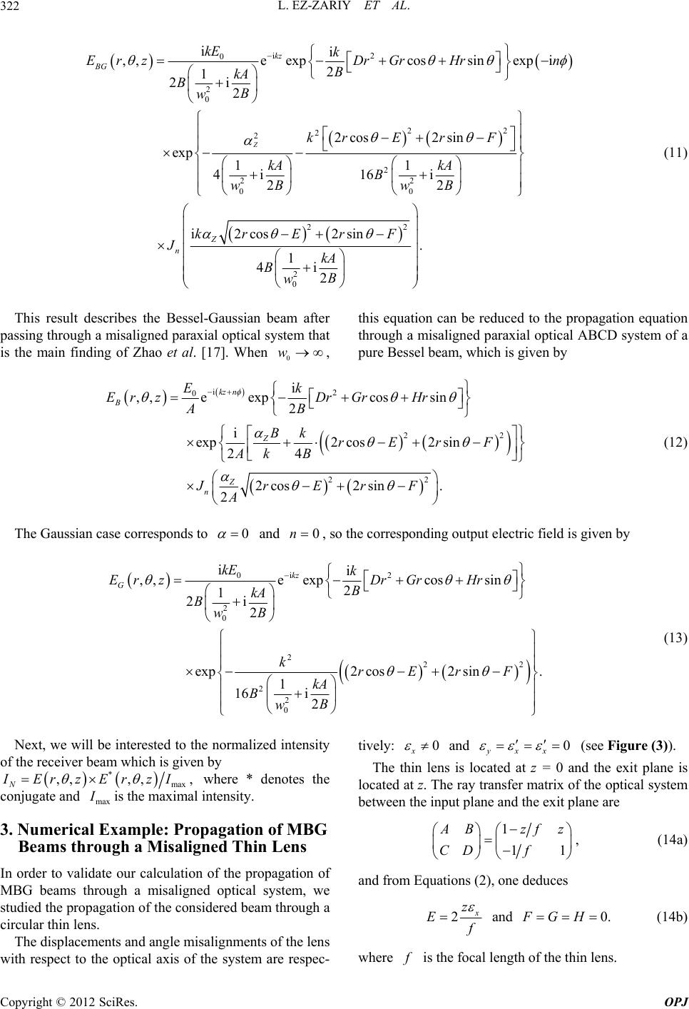 L. EZ-ZARIY ET AL. 322 i2 0 2 0 22 2 2 2 22 00 22 2 0 ii , ,eexpcossinexpi 2 1 2i 2 2cos 2sin exp 11 4i16 i 22 i2cos 2sin 1 4i 2 Z kz BG Z n kE k ErzDrGrHrn B kA BB w krE rF kA kA B BB ww kr ErF JkA Bw . B (11) This result describes the Bessel-Gaussian beam after passing through a misaligned paraxial optical system that is the main finding of Zhao et al. [17]. When 0 w, this equation can be reduced to the propagation equation through a misaligned paraxial optical ABCD system of a pure Bessel beam, which is given by i2 0 2 22 i ,,eexpcossin 2 i exp2 cos2 sin 24 2cos2sin . 2 kz n B Z Z n Ek Er zDr GrHr AB BkrErF Ak B JrErF A 2 (12) The Gaussian case corresponds to 0 and 0 n, so the corresponding output electric field is given by i2 0 2 0 222 2 2 0 ii ,,eexpcossin 2 1 2i 2 exp2 cos2 sin. 1 16i 2 kz G kE k Er zDrGrHr B kA BB w krErF kA BB w (13) Next, we will be interested to the normalized intensity of the receiver beam which is given by * max ,,,, , N IErzErzI where * denotes the conjugate and max I is the maximal intensity. 3. Numerical Example: Propagation of MBG Beams through a Misaligned Thin Lens In order to validate our calculation of the propagation of MBG beams through a misaligned optical system, we studied the propagation of the considered beam through a circular thin lens. The displacements and angle misalignments of the lens with respect to the optical axis of the system are respec- tively: 0 x and 0 yxx (see Figure (3)). The thin lens is located at z = 0 and the exit plane is located at z. The ray transfer matrix of the optical system between the input plane and the exit plane are 1 11 A Bzf CD f z , (14a) and from Equations (2), one deduces 2 x z E f and (14b) 0.FGH where f is the focal length of the thin lens. Copyright © 2012 SciRes. OPJ 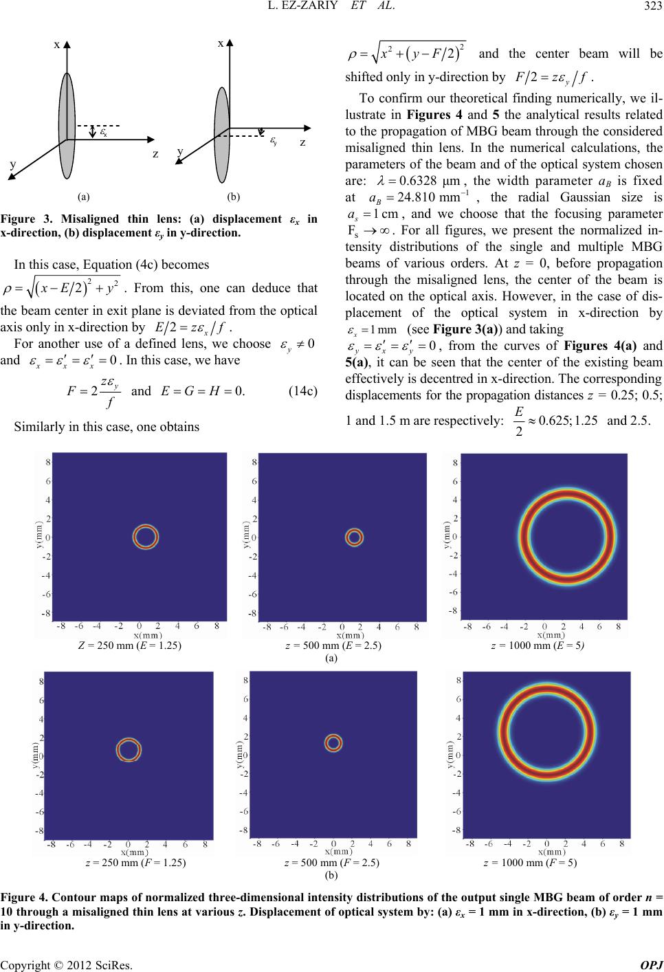 L. EZ-ZARIY ET AL. 323 z x y z x y (a) (b) Figure 3. Misaligned thin lens: (a) displacement εx in x-direction, (b) displacement εy in y-direction. In this case, Equation (4c) becomes 22 2 x E y. From this, one can deduce that the beam center in exit plane is deviated from the optical axis only in x-direction by 2x Ezf . For another use of a defined lens, we choose 0 y and 0 xxx . In this case, we have 2y z F f and 0.EGH (14c) Similarly in this case, one obtains 2 22xyF and the center beam will be shifted only in y-direction by 2y F zf . To confirm our theoretical finding numerically, we il- lustrate in Figures 4 and 5 the analytical results related to the propagation of MBG beam through the considered misaligned thin lens. In the numerical calculations, the parameters of the beam and of the optical system chosen are: 0.6328 μm , the width parameter aB is fixed at 1 24.810 mm B a 1cm , the radial Gaussian size is s a , and we choose that the focusing parameter s. For all figures, we present the normalized in- tensity distributions of the single and multiple MBG beams of various orders. At z = 0, before propagation through the misaligned lens, the center of the beam is located on the optical axis. However, in the case of dis- placement of the optical system in x-direction by F x1mm (see Figure 3(a)) and taking 0 yxy , from the curves of Figures 4(a) and 5(a), it can be seen that the center of the existing beam effectively is decentred in x-direction. The corresponding displacements for the propagation distances z = 0.25; 0.5; 1 and 1.5 m are respectively: 0.625;1.25 2 E and 2.5. Z = 250 mm (E = 1.25) z = 500 mm (E = 2.5) z = 1000 mm (E = 5) (a) z = 250 mm (F = 1.25) z = 500 mm (F = 2.5) z = 1000 mm (F = 5) (b) Figure 4. Contour maps of normalized three-dimensional intensity distributions of the output single MBG beam of order n = 10 through a misaligned thin lens at various z. Displacement of optical system by: (a) εx = 1 mm in x-direction, (b) εy = 1 mm in y-direction. Copyright © 2012 SciRes. OPJ 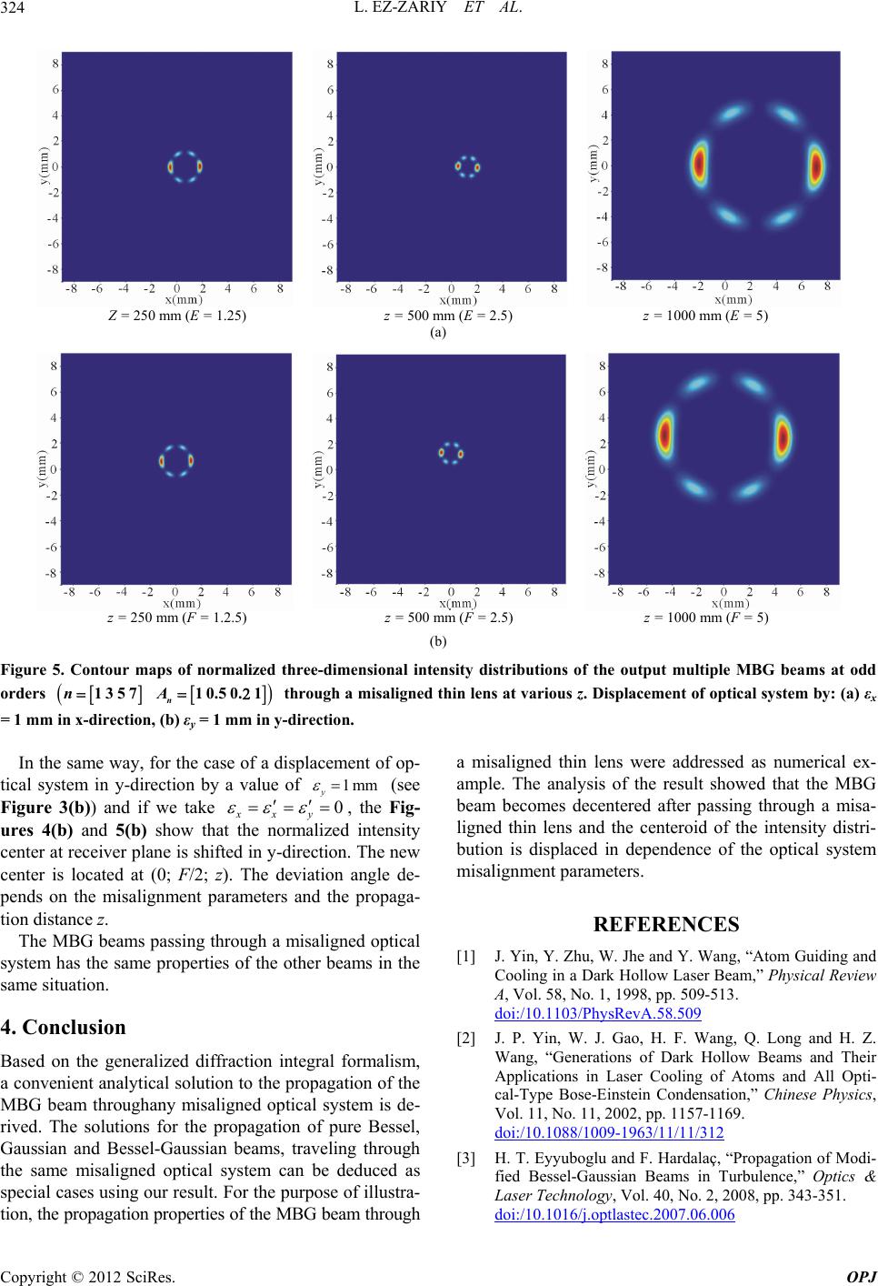 L. EZ-ZARIY ET AL. 324 Z = 250 mm (E = 1.25) z = 500 mm (E = 2.5) z = 1000 mm (E = 5) (a) z = 250 mm (F = 1.2.5) z = 500 mm (F = 2.5) z = 1000 mm (F = 5) (b) Figure 5. Contour maps of normalized three-dimensional intensity distributions of the output multiple MBG beams at odd orders 135710.50. 1 n nA through a misaligned thin lens at various z. Displacement of optical system by: (a) εx = 1 mm in x-direction, (b) εy = 1 mm in y-direction. In the same way, for the case of a displacement of op- tical system in y-direction by a value of 1mm y 0 (see Figure 3(b)) and if we take xxy , the Fig- ures 4(b) and 5(b) show that the normalized intensity center at receiver plane is shifted in y-direction. The new center is located at (0; F/2; z). The deviation angle de- pends on the misalignment parameters and the propaga- tion distance z. The MBG beams passing through a misaligned optical system has the same properties of the other beams in the same situation. 4. Conclusion Based on the generalized diffraction integral formalism, a convenient analytical solution to the propagation of the MBG beam throughany misaligned optical system is de- rived. The solutions for the propagation of pure Bessel, Gaussian and Bessel-Gaussian beams, traveling through the same misaligned optical system can be deduced as special cases using our result. For the purpose of illustra- tion, the propagation properties of the MBG beam through a misaligned thin lens were addressed as numerical ex- ample. The analysis of the result showed that the MBG beam becomes decentered after passing through a misa- ligned thin lens and the centeroid of the intensity distri- bution is displaced in dependence of the optical system misalignment parameters. REFERENCES [1] J. Yin, Y. Zhu, W. Jhe and Y. Wang, “Atom Guiding and Cooling in a Dark Hollow Laser Beam,” Physical Review A, Vol. 58, No. 1, 1998, pp. 509-513. doi:/10.1103/PhysRevA.58.509 [2] J. P. Yin, W. J. Gao, H. F. Wang, Q. Long and H. Z. Wang, “Generations of Dark Hollow Beams and Their Applications in Laser Cooling of Atoms and All Opti- cal-Type Bose-Einstein Condensation,” Chinese Physics, Vol. 11, No. 11, 2002, pp. 1157-1169. doi:/10.1088/1009-1963/11/11/312 [3] H. T. Eyyuboglu and F. Hardalaç, “Propagation of Modi- fied Bessel-Gaussian Beams in Turbulence,” Optics & Laser Technology, Vol. 40, No. 2, 2008, pp. 343-351. doi:/10.1016/j.optlastec.2007.06.006 Copyright © 2012 SciRes. OPJ 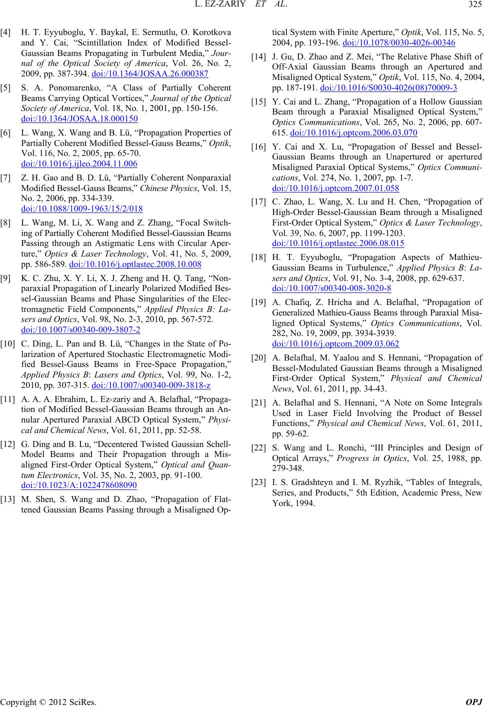 L. EZ-ZARIY ET AL. 325 [4] H. T. Eyyuboglu, Y. Baykal, E. Sermutlu, O. Korotkova and Y. Cai, “Scintillation Index of Modified Bessel- Gaussian Beams Propagating in Turbulent Media,” Jour- nal of the Optical Society of America, Vol. 26, No. 2, 2009, pp. 387-394. doi:/10.1364/JOSAA.26.000387 [5] S. A. Ponomarenko, “A Class of Partially Coherent Beams Carrying Optical Vortices,” Journal of the Optical Society of America, Vol. 18, No. 1, 2001, pp. 150-156. doi:/10.1364/JOSAA.18.000150 [6] L. Wang, X. Wang and B. Lü, “Propagation Properties of Partially Coherent Modified Bessel-Gauss Beams,” Optik, Vol. 116, No. 2, 2005, pp. 65-70. doi:/10.1016/j.ijleo.2004.11.006 [7] Z. H. Gao and B. D. Lü, “Partially Coherent Nonparaxial Modified Bessel-Gauss Beams,” Chinese Physics, Vol. 15, No. 2, 2006, pp. 334-339. doi:/10.1088/1009-1963/15/2/018 [8] L. Wang, M. Li, X. Wang and Z. Zhang, “Focal Switch- ing of Partially Coherent Modified Bessel-Gaussian Beams Passing through an Astigmatic Lens with Circular Aper- ture,” Optics & Laser Technology, Vol. 41, No. 5, 2009, pp. 586-589. doi:/10.1016/j.optlastec.2008.10.008 [9] K. C. Zhu, X. Y. Li, X. J. Zheng and H. Q. Tang, “Non- paraxial Propagation of Linearly Polarized Modified Bes- sel-Gaussian Beams and Phase Singularities of the Elec- tromagnetic Field Components,” Applied Physics B: La- sers and Optics, Vol. 98, No. 2-3, 2010, pp. 567-572. doi:/10.1007/s00340-009-3807-2 [10] C. Ding, L. Pan and B. Lü, “Changes in the State of Po- larization of Apertured Stochastic Electromagnetic Modi- fied Bessel-Gauss Beams in Free-Space Propagation,” Applied Physics B: Lasers and Optics, Vol. 99, No. 1-2, 2010, pp. 307-315. doi:/10.1007/s00340-009-3818-z [11] A. A. A. Ebrahim, L. Ez-zariy and A. Belafhal, “Propaga- tion of Modified Bessel-Gaussian Beams through an An- nular Apertured Paraxial ABCD Optical System,” Physi- cal and Chemical News, Vol. 61, 2011, pp. 52-58. [12] G. Ding and B. Lu, “Decentered Twisted Gaussian Schell- Model Beams and Their Propagation through a Mis- aligned First-Order Optical System,” Optical and Quan- tum Electronics, Vol. 35, No. 2, 2003, pp. 91-100. doi:/10.1023/A:1022478608090 [13] M. Shen, S. Wang and D. Zhao, “Propagation of Flat- tened Gaussian Beams Passing through a Misaligned Op- tical System with Finite Aperture,” Optik, Vol. 115, No. 5, 2004, pp. 193-196. doi:/10.1078/0030-4026-00346 [14] J. Gu, D. Zhao and Z. Mei, “The Relative Phase Shift of Off-Axial Gaussian Beams through an Apertured and Misaligned Optical System,” Optik, Vol. 115, No. 4, 2004, pp. 187-191. doi:/10.1016/S0030-4026(08)70009-3 [15] Y. Cai and L. Zhang, “Propagation of a Hollow Gaussian Beam through a Paraxial Misaligned Optical System,” Optics Communications, Vol. 265, No. 2, 2006, pp. 607- 615. doi:/10.1016/j.optcom.2006.03.070 [16] Y. Cai and X. Lu, “Propagation of Bessel and Bessel- Gaussian Beams through an Unapertured or apertured Misaligned Paraxial Optical Systems,” Optics Communi- cations, Vol. 274, No. 1, 2007, pp. 1-7. doi:/10.1016/j.optcom.2007.01.058 [17] C. Zhao, L. Wang, X. Lu and H. Chen, “Propagation of High-Order Bessel-Gaussian Beam through a Misaligned First-Order Optical System,” Optics & Laser Technology, Vol. 39, No. 6, 2007, pp. 1199-1203. doi:/10.1016/j.optlastec.2006.08.015 [18] H. T. Eyyuboglu, “Propagation Aspects of Mathieu- Gaussian Beams in Turbulence,” Applied Physics B: La- sers and Optics, Vol. 91, No. 3-4, 2008, pp. 629-637. doi:/10.1007/s00340-008-3020-8 [19] A. Chafiq, Z. Hricha and A. Belafhal, “Propagation of Generalized Mathieu-Gauss Beams through Paraxial Misa- ligned Optical Systems,” Optics Communications, Vol. 282, No. 19, 2009, pp. 3934-3939. doi:/10.1016/j.optcom.2009.03.062 [20] A. Belafhal, M. Yaalou and S. Hennani, “Propagation of Bessel-Modulated Gaussian Beams through a Misaligned First-Order Optical System,” Physical and Chemical News, Vol. 61, 2011, pp. 34-43. [21] A. Belafhal and S. Hennani, “A Note on Some Integrals Used in Laser Field Involving the Product of Bessel Functions,” Physical and Chemical News, Vol. 61, 2011, pp. 59-62. [22] S. Wang and L. Ronchi, “III Principles and Design of Optical Arrays,” Progress in Optics, Vol. 25, 1988, pp. 279-348. [23] I. S. Gradshteyn and I. M. Ryzhik, “Tables of Integrals, Series, and Products,” 5th Edition, Academic Press, New York, 1994. Copyright © 2012 SciRes. OPJ |