

Paper Menu >>
Journal Menu >>
 Optics and Photonics Journal, 2012, 2, 270-277 http://dx.doi.org/10.4236/opj.2012.24033 Published Online December 2012 (http://www.SciRP.org/journal/opj) Studies of Optical Properties of Symmetrical Quasi-Periodic Photonic Crystals Jihene Zaghdoudi, Nadia Maaloul, Mounir Kanzari Photovoltaic and Semiconductor Materials Laboratory, Ecole National d’Ingénieurs de Tunis, Tunis, Tunisia Email: [email protected] Received August 12, 2012; revised September 14, 2012; accepted September 28, 2012 ABSTRACT Using the transfer matrix method approach (TMM), the present paper attempts to determine the optical properties of quasi-periodic symmetric one-dimensional photonic systems. In addition, it studies hybrid hetero-structure systems constructed by using periodic and quasi-periodic multilayer systems. The effect of symmetry applied to symmetric mul- tilayer systems results in the appearance of optical windows at the photonic band gaps (PBG) of the system. The use of hybrid symmetric systems, at normal incidence in the visible range, show that the complete photonic band gap is the sum of bands from individual systems. The results show also that the width of the PBG depends on the parameters and nature of the built system. Keywords: Symmetrical Quasi-Periodic Photonic Crystals; Hybrid Photonic Crystals; Photonic Band Gap 1. Introduction Unlike electrical materials, today photonic crystals offer the prospect of controlling the flow of photons in the dielectric or metallic materials due to their periodic structure [1]. The speed at which light moves, and the fact that pho- tons do not tend to interact with transparent matter, is of enormous benefit to us. It allows us to transmit data over long distances. The advent of research into slow light is anticipated to bring in a wealth of applications, especially in the fields of telecommunications and optical data processing. Using light smartly offers many opportunities. Slow light promotes stronger light-matter interaction, it offers additional control over the spectral bandwidth of this interaction and it allows us to delay and temporarily store light in optical memories [2,3]. Quasi-periodic photonic crystals are dielectric struc- tures with non-periodic modulations of the refractive index. These systems can be considered as suitable mod- els to describe the transition from the perfect periodic structure to the random structure [4]. In this work, we have investigated the optical properties of the quasi-pe- riodic one-dimensional multilayer by using the symmet- ric structure. In the first part, we have evaluated the effect of apply- ing symmetry in quasi-periodic systems. In the second part, we have studied the reflection prop- erties of one-dimensional hybrid systems formed by combinations of periodic and quasi-periodic multilayer. The quasi-periodic photonic crystals (PCs) used in these hybrid structures are the symmetric Fibonacci sequence and the Thue-Morse sequence. The numerical results are presented in the visible spectral range [0.3, 1] µm for normal incidence. 2. Problem Formulation and Quasi-Periodic Models The method used to calculate the optical response of symmetric quasiperiodic systems in one-dimensional (1D) photonic crystals is the transfer matrix method (TMM) described by Yeh [5]. This method is widely applied for calculating the transmission and reflection spectra of lay- ered structures because it is quite simple and at the same time, it is a very powerful tool for simulation of light propagation through the layered structures and for calcu- lating the matrix product very quickly. TMM method consists in the calculation of the back- ward E− and the forward E+ propagating electric field components. This method shows that the relation be- tween the amplitudes of the electric fields between two different planes including a stratified medium is given by the following matrix product: 01 123 1 01 m m m EE CCC C EE where j C represent the product of the propagation ma- C opyright © 2012 SciRes. OPJ 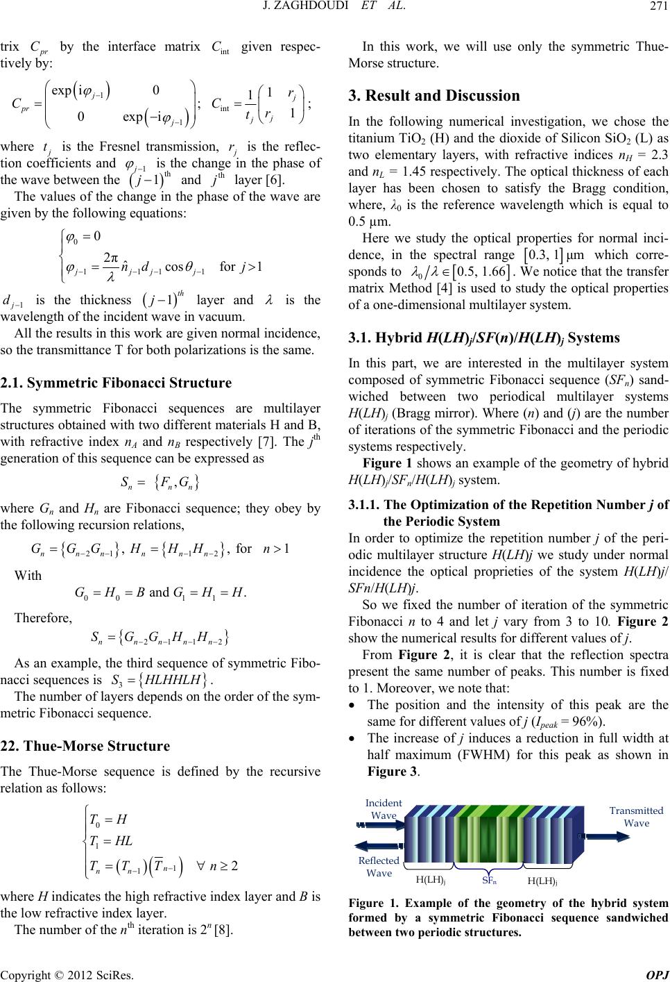 J. ZAGHDOUDI ET AL. 271 trix p r by the interface matrix given respec- tively by: Cint C 1 int 1 exp i01 1 ;1 0expi j j pr j j j r CC r t ; where j t is the Fresnel transmission, j r is the reflec- tion coefficients and 1 j j is the change in the phase of the wave between the and layer [6]. th 1th j The values of the change in the phase of the wave are given by the following equations: 0 1111 for j 0 2πˆcos 1 jjj nd j 1 j d is the thickness layer and 1th j is the wavelength of the incident wave in vacuum. All the results in this work are given normal incidence, so the transmittance T for both polarizations is the same. 2.1. Symmetric Fibonacci Structure The symmetric Fibonacci sequences are multilayer structures obtained with two different materials H and B, with refractive index nA and nB respectively [7]. The jth generation of this sequence can be expressed as , nn SFGn 2 , , n H 1 H 2 H where Gn and Hn are Fibonacci sequence; they obey by the following recursion relations, 211 for1 nnnn n GGGH Hn With 00 1 and .GHB GH Therefore, 21 1n nnnn SGGH As an example, the third sequence of symmetric Fibo- nacci sequences is . S HLHHLH 3 The number of layers depends on the order of the sym- metric Fibonacci sequence. 22. Thue-Morse Structure The Thue-Morse sequence is defined by the recursive relation as follows: 0 1 1 12 n n nn TH THL TTT where H indicates the high refractive index layer and B is the low refractive index layer. The number of the nth iteration is 2n [8]. In this work, we will use only the symmetric Thue- Morse structure. 3. Result and Discussion In the following numerical investigation, we chose the titanium TiO2 (H) and the dioxide of Silicon SiO2 (L) as two elementary layers, with refractive indices nH = 2.3 and nL = 1.45 respectively. The optical thickness of each layer has been chosen to satisfy the Bragg condition, where, λ0 is the reference wavelength which is equal to 0.5 µm. Here we study the optical properties for normal inci- dence, in the spectral range 0.3, 1μm which corre- sponds to 00.5, 1.66 . We notice that the transfer matrix Method [4] is used to study the optical properties of a one-dimensional multilayer system. 3.1. Hybrid H(LH)j/SF(n)/H(LH)j Systems In this part, we are interested in the multilayer system composed of symmetric Fibonacci sequence (SFn) sand- wiched between two periodical multilayer systems H(LH)j (Bragg mirror). Where (n) and (j) are the number of iterations of the symmetric Fibonacci and the periodic systems respectively. Figure 1 shows an example of the geometry of hybrid H(LH)j/SFn/H(LH)j system. 3.1.1. The Optimization of the Repetition Number j of the Periodic System In order to optimize the repetition number j of the peri- odic multilayer structure H(LH)j we study under normal incidence the optical proprieties of the system H(LH)j/ SFn/H(LH)j. So we fixed the number of iteration of the symmetric Fibonacci n to 4 and let j vary from 3 to 10. Figure 2 show the numerical results for different values of j. From Figure 2, it is clear that the reflection spectra present the same number of peaks. This number is fixed to 1. Moreover, we note that: The position and the intensity of this peak are the same for different values of j (Ipeak = 96%). The increase of j induces a reduction in full width at half maximum (FWHM) for this peak as shown in Figure 3. Transmitted Wave Reflected Wave Incident Wave H(LH) j SF n H(LH) j Figure 1. Example of the geometry of the hybrid system formed by a symmetric Fibonacci sequence sandwiched etween two periodic structures. b Copyright © 2012 SciRes. OPJ 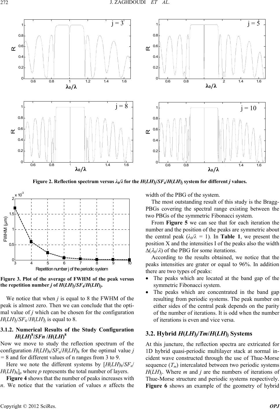 J. ZAGHDOUDI ET AL. Copyright © 2012 SciRes. OPJ 272 0.6 0.811.2 1.4 1.6 0 0.2 0.4 0.6 0.8 1 R 0/ j = 3 λ0/λ 0.6 0.811.2 1.41.6 0 0.2 0.4 0.6 0.8 1 R 0/ j = 5 λ 0 / λ 0.6 0.811.2 1.4 1.6 0 0.2 0.4 0.6 0.8 1 R 0/ j = 8 λ 0 / λ 0.6 0.8 11.21.4 1.6 0 0.2 0.4 0.6 0.8 1 R 0/ j = 10 λ0/λ Figure 2. Reflection spectrum versus λ0/λ for the H(LH)j/SF4/H(LH)j system for different j values. 345678910 0 0.5 1 1.5 2x 1 0 -3 Repetition number j of the periodic system FWHM (µm) Figure 3. Plot of the average of FWHM of the peak versus the repetition number j of H(LH)j/SF4/H(LH)j. We notice that when j is equal to 8 the FWHM of the peak is almost zero. Then we can conclude that the opti- mal value of j which can be chosen for the configuration H(LH)j/SF4 /H(LH)j is equal to 8. 3.1.2. Numerical Results of the Study Configuration H(LH)8/SFn /H(LH)8 Now we move to study the reflection spectrum of the configuration H(LH )8/SFn/H(LH)8 for the optimal value j = 8 and for different values of n ranges from 3 to 9. Here we note the different systems by [H(LH)8/SFn/ H(LH)8]p where p represents the total number of layers. Figure 4 shows that the number of peaks increases with n. We notice that the variation of values n affects the width of the PBG of the system. The most outstanding result of this study is the Bragg- PBGs covering the spectral range existing between the two PBGs of the symmetric Fibonacci system. From Figure 5 we can see that for each iteration the number and the position of the peaks are symmetric about the central peak (λ0/λ = 1). In Table 1, we present the position X and the intensities I of the peaks also the width ( 0/ ) of the PBG for some iterations. According to the results obtained, we notice that the peaks intensities are grater or equal to 96%. In addition there are two types of peaks: The peaks which are located at the band gap of the symmetric Fibonacci system. The peaks which are concentrated in the band gap resulting from periodic systems. The peak number on either sides of the central peak depends on the parity of the number of iterations. It is odd when the number of iterations is even and vice versa. 3.2. Hybrid H(LH)j/Tm/H(LH)j Systems At this juncture, the reflection spectra are extricated for 1D hybrid quasi-periodic multilayer stack at normal in- cident wave constructed through the use of Thue-Morse sequence (Tm) intercalated between two periodic systems H(LH)j. Where m and j are the numbers of iterations of Thue-Morse structure and periodic systems respectively. Figure 6 shows an example of the geometry of hybrid 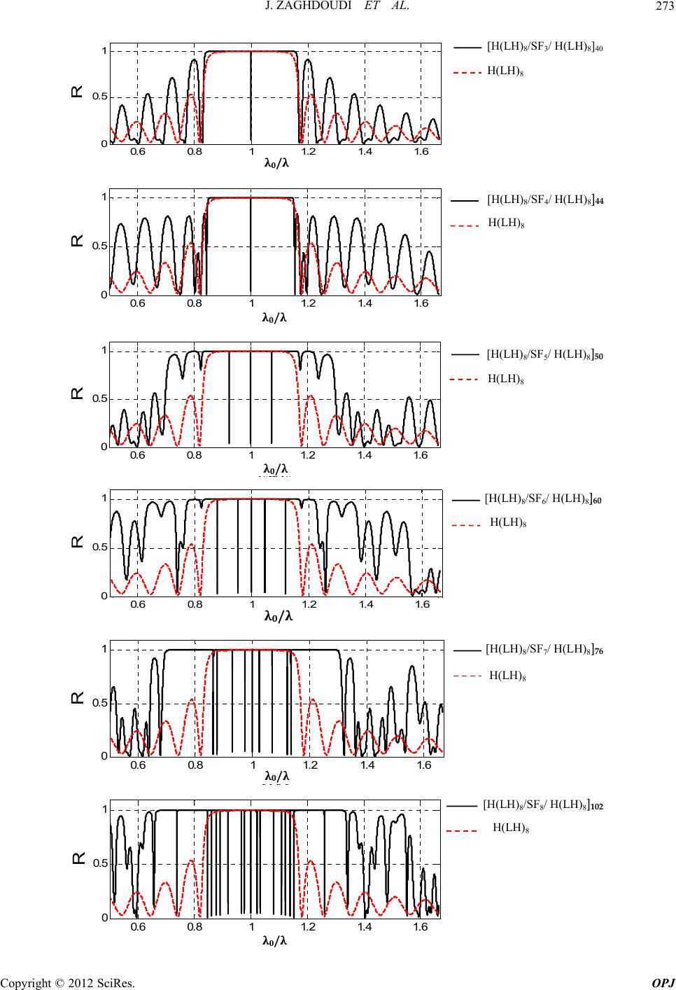 J. ZAGHDOUDI ET AL. 273 0.6 0.811.21.4 1.6 0 0.5 1 R 0/ H(LH) 8 [H(LH) 8 /SF 3 / H(LH) 8 ] 40 λ 0 /λ 0.6 0.811.21.4 1.6 0 0.5 1 R 0/ H(LH) 8 [H(LH) 8 /SF 4 / H(LH) 8 ] 44 λ 0 /λ 0.6 0.8 11.2 1.4 1.6 0 0.5 1 R 0/ H(LH) 8 [H(LH) 8 /SF 5 / H(LH) 8] 50 λ 0 /λ 0.6 0.811.21.4 1.6 0 0.5 1 R 0/ H(LH) 8 [H(LH) 8 /SF 6 / H(LH) 8 ] 60 λ 0 /λ 0.6 0.811.2 1.41.6 0 0.5 1 R 0/ H(LH) 8 [H(LH) 8 /SF 7 / H(LH) 8] 76 λ 0 /λ 0.6 0.811.21.4 1.6 0 0.5 1 R 0/ λ 0 / λ H(LH) 8 [H(LH) 8 /SF 8 / H(LH) 8 ] 102 Copyright © 2012 SciRes. OPJ 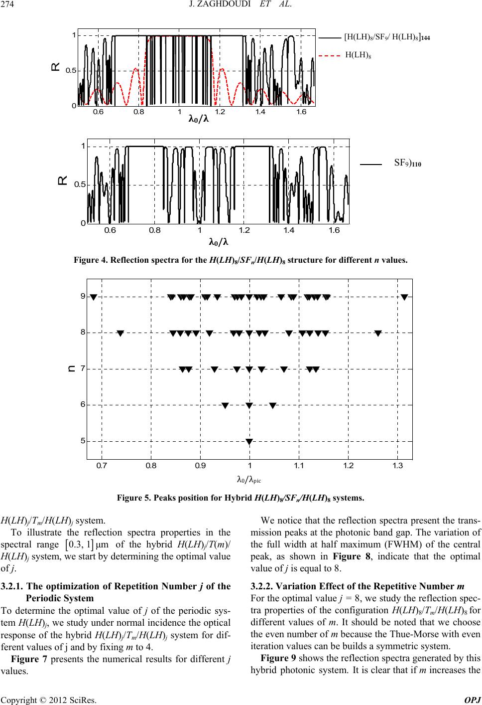 J. ZAGHDOUDI ET AL. 274 0.6 0.811.2 1.4 1.6 0 0.5 1 R 0/ λ 0 /λ H(LH) 8 [H(LH) 8 /SF 9 / H(LH) 8 ] 144 0.6 0.8 11.2 1.4 1.6 0 0.5 1 R 0/ SF 9 ) 110 λ 0 / λ Figure 4. Reflection spectra for the H(LH)8/SFn/H(LH)8 structure for different n values. 0.7 0.8 0.911.1 1.2 1.3 5 6 7 8 9 n 0/pic λ0/λpic Figure 5. Peaks position for Hybrid H(LH)8/SFn/H(LH)8 systems. H(LH)j/Tm/H(LH)j system. To illustrate the reflection spectra properties in the spectral range 0.3, 1μm of the hybrid H(LH)j/T(m)/ H(LH)j system, we start by determining the optimal value of j. 3.2.1. The optimization of Repetition Number j of the Periodic System To determine the optimal value of j of the periodic sys- tem H(LH)j, we study under normal incidence the optical response of the hybrid H(LH)j/Tm/H(LH)j system for dif- ferent values of j and by fixing m to 4. Figure 7 presents the numerical results for different j values. We notice that the reflection spectra present the trans- mission peaks at the photonic band gap. The variation of the full width at half maximum (FWHM) of the central peak, as shown in Figure 8, indicate that the optimal value of j is equal to 8. 3.2.2. Variation Effect of the Repetitive Number m For the optimal value j = 8, we study the reflection spec- tra properties of the configuration H(LH)8/Tm/H(LH)8 for different values of m. It should be noted that we choose the even number of m because the Thue-Morse with even iteration values can be builds a symmetric system. Figure 9 shows the reflection spectra generated by this hybrid photonic system. It is clear that if m increases the Copyright © 2012 SciRes. OPJ 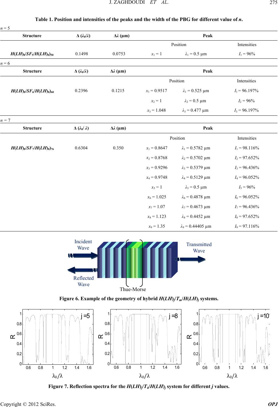 J. ZAGHDOUDI ET AL. 275 Table 1. Position and intensities of the peaks and the width of the PBG for different value of n. n = 5 Structure Δ (λ0/λ) Δλ (µm) Peak Position Intensities H(LH)8/SF5/H(LH)8)50 0.1498 0.0753 x1 = 1 λ1 = 0.5 µm I1 = 96% n = 6 Structure Δ (λ0/λ) Δλ (µm) Peak Position Intensities H(LH)8/SF6/H(LH)8)60 0.2396 0.1215 x1 = 0.9517 λ1 = 0.525 µm I1 = 96.197% x2 = 1 λ2 = 0.5 µm I2 = 96% x3 = 1.048 λ3 = 0.477 µm I3 = 96.197% n = 7 Structure Δ (λ0/ λ) Δλ (µm) Peak Position Intensities H(LH)8/SF7/H(LH)8)76 0.6304 0.350 x1 = 0.8647 λ1 = 0.5782 µm I1 = 98.116% x2 = 0.8768 λ2 = 0.5702 µm I2 = 97.652% x3 = 0.9296 λ3 = 0.5379 µm I3 = 96.436% x4 = 0.9748 λ4 = 0.5129 µm I4 = 96.052% x5 = 1 λ5 = 0.5 µm I5 = 96% x6 = 1.025 λ6 = 0.4878 µm I6 = 96.052% x7 = 1.07 λ7 = 0.4673 µm I7 = 96.436% x8 = 1.123 λ8 = 0.4452 µm I8 = 97.652% x9 = 1.35 λ9 = 0.44405 µm I9 = 97.116% Transmitted Wave Reflected Wave Incident Wave Thue-Morse Figure 6. Example of the geometry of hybrid H(LH)j/Tm/H(LH)j systems. 0.6 0.811.2 1.4 1.6 0 0.2 0.4 0.6 0.8 1 R 0/ j = 1 0 0.6 0.811.2 1.4 1.6 0 0.2 0.4 0.6 0.8 1 R 0/ j = 8 0.6 0.811.2 1.4 1.6 0 0.2 0.4 0.6 0.8 1 R 0/ j = 5 λ 0 /λ λ 0 /λ λ 0 /λ Figure 7. Reflection spectra for the H(LH)j/T4/H(LH)j system for different j values. Copyright © 2012 SciRes. OPJ 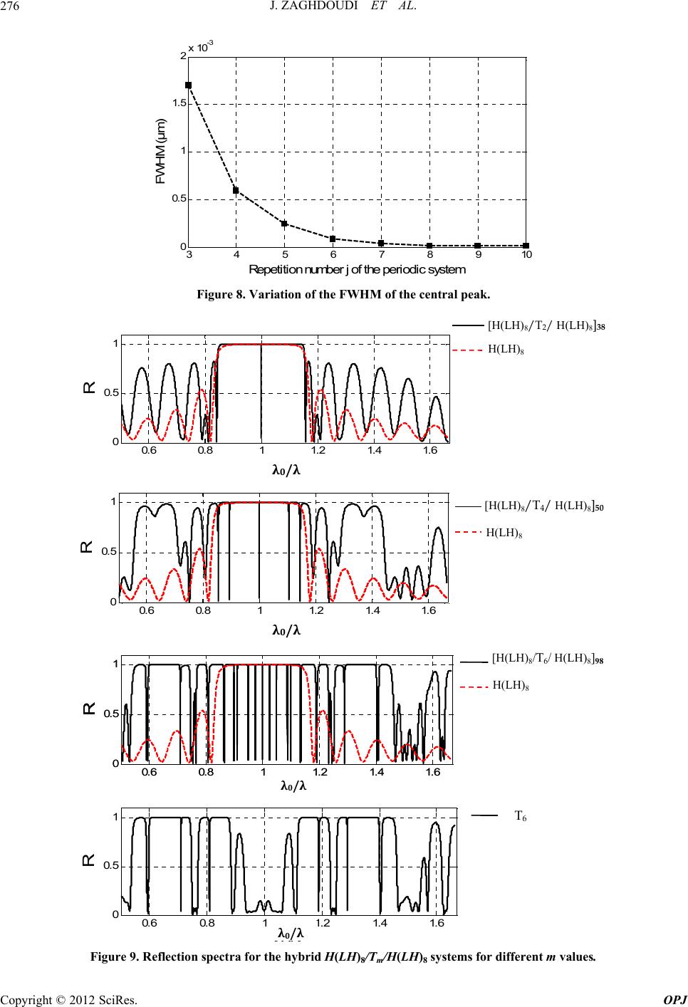 J. ZAGHDOUDI ET AL. 276 345678910 0 0.5 1 1.5 2x 10⁻³ R epetition n um ber j of the periodic system FW HM (µm ) Figure 8. Variation of the FWHM of the central peak. 0.6 0.811.2 1.4 1.6 0 0.5 1 R 0/ λ 0 /λ H(LH) 8 [H(LH) 8 /T 2 / H(LH) 8] 38 0.6 0.811.21.4 1.6 0 0.5 1 R 0/ λ 0 /λ H(LH)8 [H(LH)8 /T 4 / H(LH)8 ] 50 0.6 0.811.21.4 1.6 0 0.5 1 R 0/ 0.6 0.811.21.4 1.6 0 0.5 1 R 0/ λ 0 /λ H(LH) 8 [H(LH) 8 /T 6 / H(LH) 8 ] 98 0.6 0.811.21.4 1.6 0 0.5 1 R 0/ T 6 λ 0 /λ Figure 9. Reflection spectra for the hybrid H(LH)8/Tm/H(LH)8 systems for different m values. Copyright © 2012 SciRes. OPJ 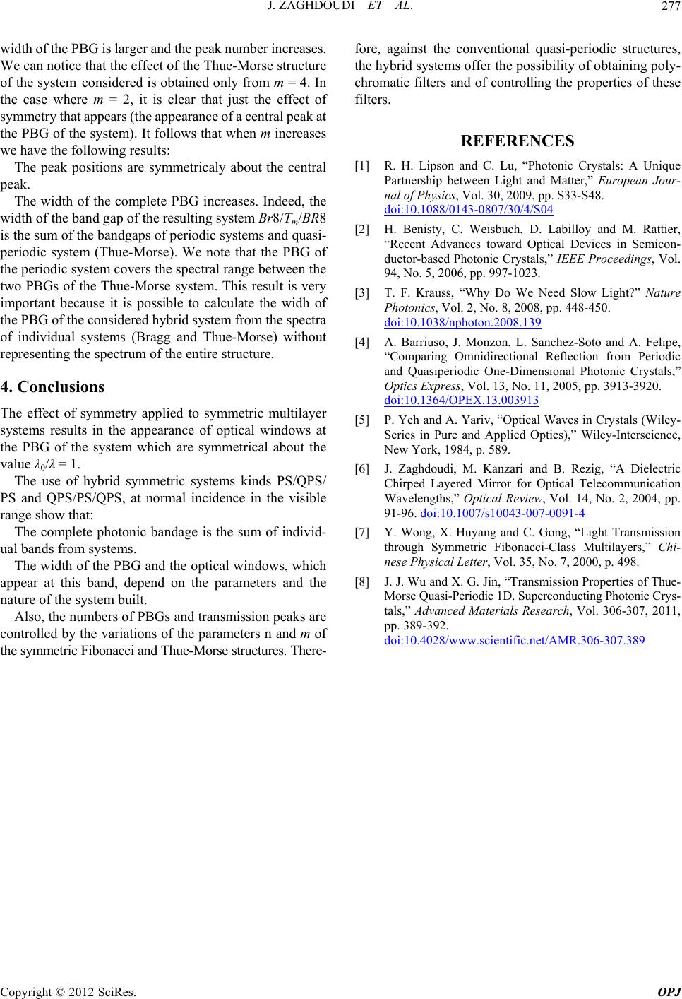 J. ZAGHDOUDI ET AL. Copyright © 2012 SciRes. OPJ 277 width of the PBG is larger and the peak number increases. We can notice that the effect of the Thue-Morse structure of the system considered is obtained only from m = 4. In the case where m = 2, it is clear that just the effect of symmetry that appears (the appearance of a central peak at the PBG of the system). It follows that when m increases we have the following results: The peak positions are symmetricaly about the central peak. The width of the complete PBG increases. Indeed, the width of the band gap of the resulting system Br8/Tm/BR8 is the sum of the bandgaps of periodic systems and quasi- periodic system (Thue-Morse). We note that the PBG of the periodic system covers the spectral range between the two PBGs of the Thue-Morse system. This result is very important because it is possible to calculate the widh of the PBG of the considered hybrid system from the spectra of individual systems (Bragg and Thue-Morse) without representing the spectrum of the entire structure. 4. Conclusions The effect of symmetry applied to symmetric multilayer systems results in the appearance of optical windows at the PBG of the system which are symmetrical about the value λ0/λ = 1. The use of hybrid symmetric systems kinds PS/QPS/ PS and QPS/PS/QPS, at normal incidence in the visible range show that: The complete photonic bandage is the sum of individ- ual bands from systems. The width of the PBG and the optical windows, which appear at this band, depend on the parameters and the nature of the system built. Also, the numbers of PBGs and transmission peaks are controlled by the variations of the parameters n and m of the symmetric Fibonacci and Thue-Morse structures. There- fore, against the conventional quasi-periodic structures, the hybrid systems offer the possibility of obtaining poly- chromatic filters and of controlling the properties of these filters. REFERENCES [1] R. H. Lipson and C. Lu, “Photonic Crystals: A Unique Partnership between Light and Matter,” European Jour- nal of Physics, Vol. 30, 2009, pp. S33-S48. doi:10.1088/0143-0807/30/4/S04 [2] H. Benisty, C. Weisbuch, D. Labilloy and M. Rattier, “Recent Advances toward Optical Devices in Semicon- ductor-based Photonic Crystals,” IEEE Proceedings, Vol. 94, No. 5, 2006, pp. 997-1023. [3] T. F. Krauss, “Why Do We Need Slow Light?” Nature Photonics, Vol. 2, No. 8, 2008, pp. 448-450. doi:10.1038/nphoton.2008.139 [4] A. Barriuso, J. Monzon, L. Sanchez-Soto and A. Felipe, “Comparing Omnidirectional Reflection from Periodic and Quasiperiodic One-Dimensional Photonic Crystals,” Optics Express, Vol. 13, No. 11, 2005, pp. 3913-3920. doi:10.1364/OPEX.13.003913 [5] P. Yeh and A. Yariv, “Optical Waves in Crystals (Wiley- Series in Pure and Applied Optics),” Wiley-Interscience, New York, 1984, p. 589. [6] J. Zaghdoudi, M. Kanzari and B. Rezig, “A Dielectric Chirped Layered Mirror for Optical Telecommunication Wavelengths,” Optical Review, Vol. 14, No. 2, 2004, pp. 91-96. doi:10.1007/s10043-007-0091-4 [7] Y. Wong, X. Huyang and C. Gong, “Light Transmission through Symmetric Fibonacci-Class Multilayers,” Chi- nese Physical Letter, Vol. 35, No. 7, 2000, p. 498. [8] J. J. Wu and X. G. Jin, “Transmission Properties of Thue- Morse Quasi-Periodic 1D. Superconducting Photonic Crys- tals,” Advanced Materials Research, Vol. 306-307, 2011, pp. 389-392. doi:10.4028/www.scientific.net/AMR.306-307.389 |