

Paper Menu >>
Journal Menu >>
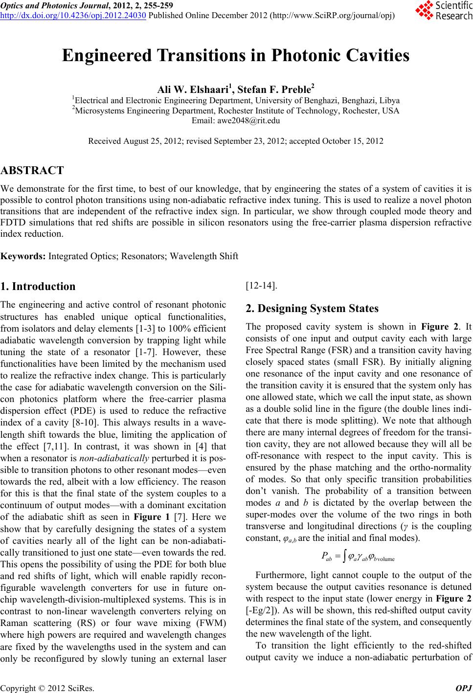 Optics and Photonics Journal, 2012, 2, 255-259 http://dx.doi.org/10.4236/opj.2012.24030 Published Online December 2012 (http://www.SciRP.org/journal/opj) Engineered Transitions in Photonic Cavities Ali W. Elshaari1, Stefan F. Preble2 1Electrical and Electronic Engineering Department, University of Benghazi, Benghazi, Libya 2Microsystems Engineering Department, Rochester Institute of Technology, Rochester, USA Email: [email protected] Received August 25, 2012; revised September 23, 2012; accepted October 15, 2012 ABSTRACT We demonstrate for the first time, to best of our knowledge, that by engineering the states of a system of cavities it is possible to control photon transitions using non-adiabatic refractive index tuning. This is used to realize a novel photon transitions that are independent of the refractive index sign. In particular, we show through coupled mode theory and FDTD simulations that red shifts are possible in silicon resonators using the free-carrier plasma dispersion refractive index reduction. Keywords: Integrated Optics; Resonators; Wavelength Shift 1. Introduction The engineering and active control of resonant photonic structures has enabled unique optical functionalities, from isolators and delay elements [1-3] to 100% efficient adiabatic wavelength conversion by trapping light while tuning the state of a resonator [1-7]. However, these functionalities have been limited by the mechanism used to realize the refractive index change. This is particularly the case for adiabatic wavelength conversion on the Sili- con photonics platform where the free-carrier plasma dispersion effect (PDE) is used to reduce the refractive index of a cavity [8-10]. This always results in a wave- length shift towards the blue, limiting the application of the effect [7,11]. In contrast, it was shown in [4] that when a resonator is non-adiabatically perturbed it is pos- sible to transition photons to other resonant modes—even towards the red, albeit with a low efficiency. The reason for this is that the final state of the system couples to a continuum of output modes—with a dominant excitation of the adiabatic shift as seen in Figure 1 [7]. Here we show that by carefully designing the states of a system of cavities nearly all of the light can be non-adiabati- cally transitioned to just one state—even towards the red. This opens the possibility of using the PDE for both blue and red shifts of light, which will enable rapidly recon- figurable wavelength converters for use in future on- chip wavelength-division-multiplexed systems. This is in contrast to non-linear wavelength converters relying on Raman scattering (RS) or four wave mixing (FWM) where high powers are required and wavelength changes are fixed by the wavelengths used in the system and can only be reconfigured by slowly tuning an external laser [12-14]. 2. Designing System States The proposed cavity system is shown in Figure 2. It consists of one input and output cavity each with large Free Spectral Range (FSR) and a transition cavity having closely spaced states (small FSR). By initially aligning one resonance of the input cavity and one resonance of the transition cavity it is ensured that the system only has one allowed state, which we call the input state, as shown as a double solid line in the figure (the double lines indi- cate that there is mode splitting). We note that although there are many internal degrees of freedom for the transi- tion cavity, they are not allowed because they will all be off-resonance with respect to the input cavity. This is ensured by the phase matching and the ortho-normality of modes. So that only specific transition probabilities don’t vanish. The probability of a transition between modes a and b is dictated by the overlap between the super-modes over the volume of the two rings in both transverse and longitudinal directions (γ is the coupling constant, φa,b are the initial and final modes). volumeaba ab b P Furthermore, light cannot couple to the output of the system because the output cavities resonance is detuned with respect to the input state (lower energy in Figure 2 [-Eg/2]). As will be shown, this red-shifted output cavity determines the final state of the system, and consequently the new wavelength of the light. To transition the light efficiently to the red-shifted ouput cavity we induce a non-adiabatic perturbation of t C opyright © 2012 SciRes. OPJ 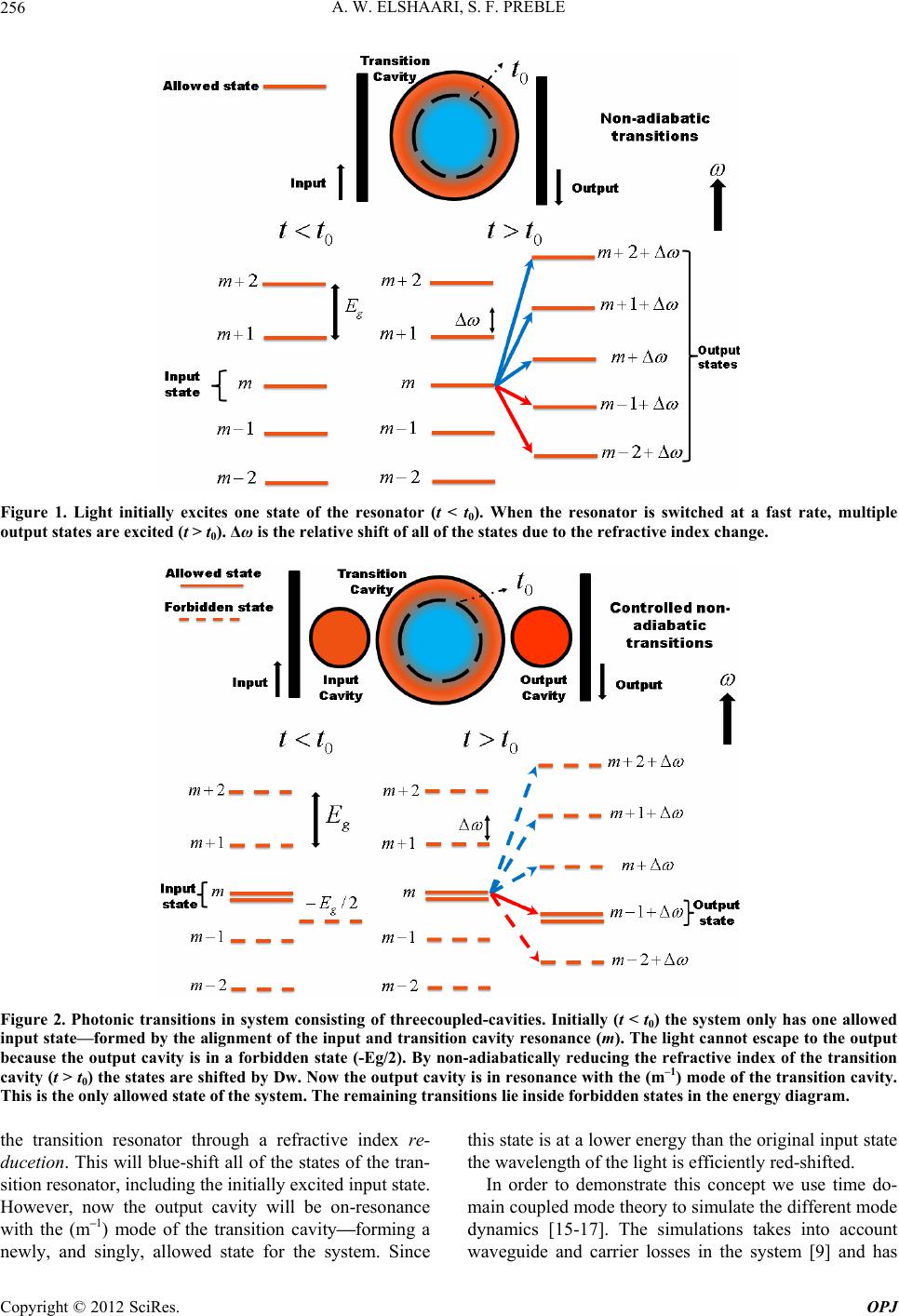 A. W. ELSHAARI, S. F. PREBLE 256 Figure 1. Light initially excites one state of the resonator (t < t0). When the resonator is switched at a fast rate, multiple output states are excited (t > t0). Δω is the relative shift of all of the states due to the refractive index change. Figure 2. Photonic transitions in system consisting of threecoupled-cavities. Initially (t < t0) the system only has one allowed input state—formed by the alignment of the input and transition cavity resonance (m). The light cannot escape to the output because the output cavity is in a forbidden state (-Eg/2). By non-adiabatically reducing the refractive index of the transition cavity (t > t0) the states are shifted by Dw. Now the output cavity is in resonance with the (m–1) mode of the transition cavity. This is the only allowed state of the system. The remaining transitions lie inside forbidden states in the energy diagram. the transition resonator through a refractive index re- ducetion. This will blue-shift all of the states of the tran- sition resonator, including the initially excited input state. However, now the output cavity will be on-resonance with the (m–1) mode of the transition cavity—forming a newly, and singly, allowed state for the system. Since this state is at a lower energy than the original input state the wavelength of the light is efficiently red-shifted. In order to demonstrate this concept we use time do- main coupled mode theory to simulate the different mode dynamics [15-17]. The simulations takes into account waveguide and carrier losses in the system [9] and has Copyright © 2012 SciRes. OPJ 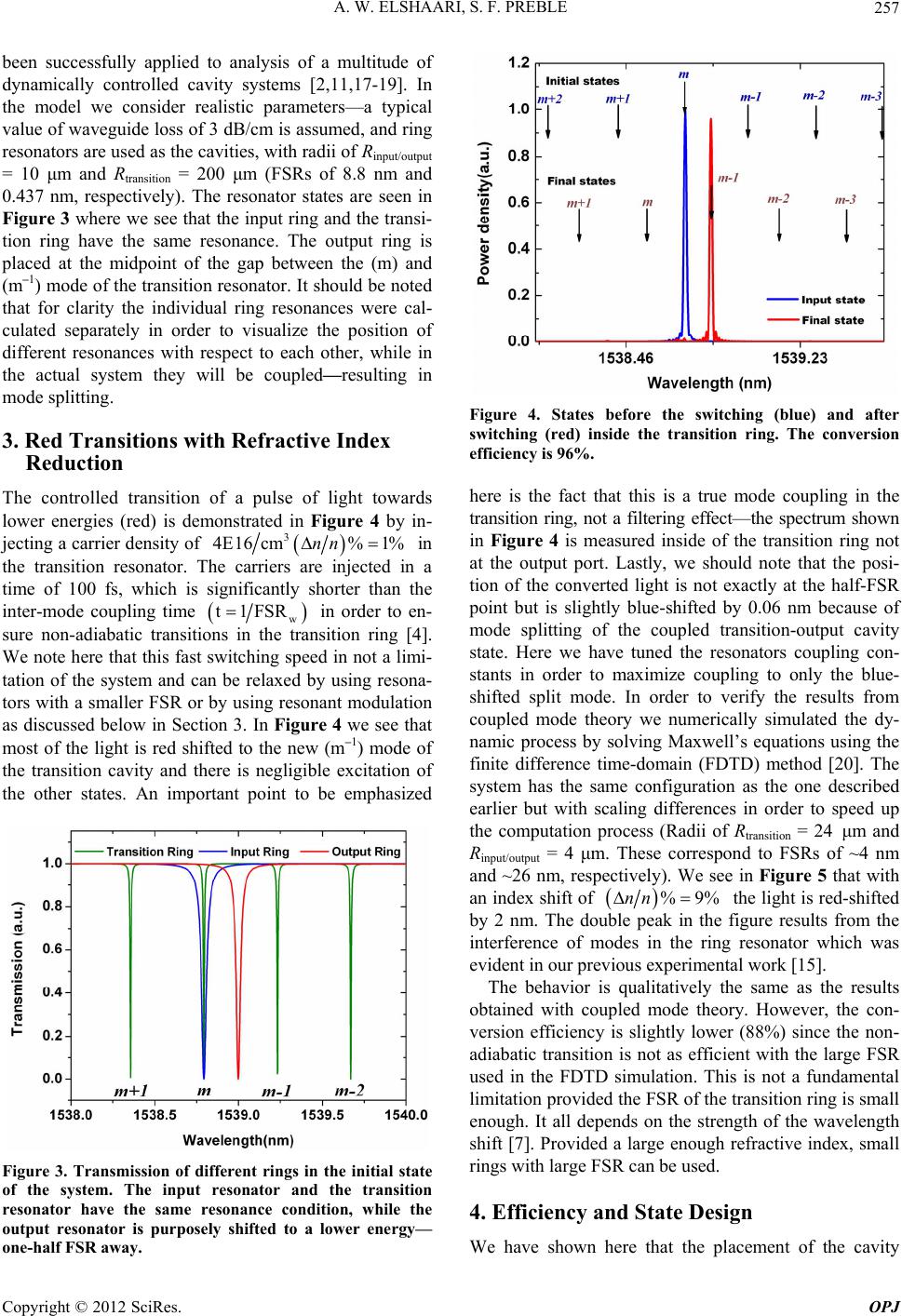 A. W. ELSHAARI, S. F. PREBLE 257 been successfully applied to analysis of a multitude of dynamically controlled cavity systems [2,11,17-19]. In the model we consider realistic parameters—a typical value of waveguide loss of 3 dB/cm is assumed, and ring resonators are used as the cavities, with radii of Rinput/output = 10 μm and Rtransition = 200 μm (FSRs of 8.8 nm and 0.437 nm, respectively). The resonator states are seen in Figure 3 where we see that the input ring and the transi- tion ring have the same resonance. The output ring is placed at the midpoint of the gap between the (m) and (m–1) mode of the transition resonator. It should be noted that for clarity the individual ring resonances were cal- culated separately in order to visualize the position of different resonances with respect to each other, while in the actual system they will be coupled—resulting in mode splitting. 3. Red Transitions with Refractive Index Reduction The controlled transition of a pulse of light towards lower energies (red) is demonstrated in Figure 4 by in- jecting a carrier density of 3 4E16 cm%1%nn in the transition resonator. The carriers are injected in a time of 100 fs, which is significantly shorter than the inter-mode coupling time w t1FSR in order to en- sure non-adiabatic transitions in the transition ring [4]. We note here that this fast switching speed in not a limi- tation of the system and can be relaxed by using resona- tors with a smaller FSR or by using resonant modulation as discussed below in Section 3. In Figure 4 we see that most of the light is red shifted to the new (m–1) mode of the transition cavity and there is negligible excitation of the other states. An important point to be emphasized Figure 3. Transmission of different rings in the initial state of the system. The input resonator and the transition resonator have the same resonance condition, while the output resonator is purposely shifted to a lower energy— one-half FSR away. Figure 4. States before the switching (blue) and after switching (red) inside the transition ring. The conversion efficiency is 96%. here is the fact that this is a true mode coupling in the transition ring, not a filtering effect—the spectrum shown in Figure 4 is measured inside of the transition ring not at the output port. Lastly, we should note that the posi- tion of the converted light is not exactly at the half-FSR point but is slightly blue-shifted by 0.06 nm because of mode splitting of the coupled transition-output cavity state. Here we have tuned the resonators coupling con- stants in order to maximize coupling to only the blue- shifted split mode. In order to verify the results from coupled mode theory we numerically simulated the dy- namic process by solving Maxwell’s equations using the finite difference time-domain (FDTD) method [20]. The system has the same configuration as the one described earlier but with scaling differences in order to speed up the computation process (Radii of Rtransition = 24 μm and Rinput/output = 4 μm. These correspond to FSRs of ~4 nm and ~26 nm, respectively). We see in Figure 5 that with an index shift of %9%nn the light is red-shifted by 2 nm. The double peak in the figure results from the interference of modes in the ring resonator which was evident in our previous experimental work [15]. The behavior is qualitatively the same as the results obtained with coupled mode theory. However, the con- version efficiency is slightly lower (88%) since the non- adiabatic transition is not as efficient with the large FSR used in the FDTD simulation. This is not a fundamental limitation provided the FSR of the transition ring is small enough. It all depends on the strength of the wavelength shift [7]. Provided a large enough refractive index, small rings with large FSR can be used. 4. Efficiency and State Design We have shown here that the placement of the cavity Copyright © 2012 SciRes. OPJ 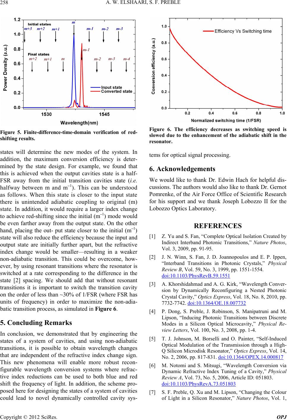 A. W. ELSHAARI, S. F. PREBLE 258 Figure 5. Finite-difference-time-domain verification of red- shifting results. states will determine the new modes of the system. In addition, the maximum conversion efficiency is deter- mined by the state design. For example, we found that this is achieved when the output cavities state is a half- FSR away from the initial transition cavities state (i.e. halfway between m and m–1). This can be understood as follows. When this state is closer to the input state there is unintended adiabatic coupling to original (m) state. In addition, it would require a larger index change to achieve red-shifting since the initial (m–1) mode would be even farther away from the output state. On the other hand, placing the out- put state closer to the initial (m–1) state will also reduce the efficiency because the input and output state are initially further apart, but the refractive index change would be smaller—resulting in a weaker non-adiabatic transition. This could be overcome, how- ever, by using resonant transitions where the resonator is switched at a rate corresponding to the difference in the state [2] spacing. We should add that without resonant transitions it is important to switch the transition cavity on the order of less than ~30% of 1/FSR (where FSR has units of frequency) in order to maximize the non-adia- batic transition process, as simulated in Figure 6. 5. Concluding Remarks In conclusion, we demonstrated that by engineering the states of a system of cavities, and using non-adiabatic transitions, it is possible to obtain wavelength changes that are independent of the refractive index change sign. This new phenomena will enable more robust recon- figurable wavelength conversion systems where refrac- tive index reductions can be used to both blue and red shift the frequency of light. In addition, the scheme pro- posed here for designing the states of a system of cavities could lead to novel dynamically controlled cavity sys- Figure 6. The efficiency decreases as switching speed is slowed due to the enhancement of the adiabatic shift in the resonator. tems for optical signal processing. 6. Acknowledgements We would like to thank Dr. Edwin Hach for helpful dis- cussions. The authors would also like to thank Dr. Gernot Pomrenke, of the Air Force Office of Scientific Research for his support and we thank Joseph Lobozzo II for the Lobozzo Optics Laboratory. REFERENCES [1] Z. Yu and S. Fan, “Complete Optical Isolation Created by Indirect Interband Photonic Transitions,” Nature Photos, Vol. 3, 2009, pp. 91-95. [2] J. N. Winn, S. Fan, J. D. Joannopoulos and E. P. Ippen, “Interband Transitions in Photonic Crystals,” Physical Review B, Vol. 59, No. 3, 1999, pp. 1551-1554. doi:10.1103/PhysRevB.59.1551 [3] A. Khorshidahmad and A. G. Kirk, “Wavelength Conver- sion by Dynamically Reconfiguring a Nested Photonic Crystal Cavity,” Optics Express, Vol. 18, No. 8, 2010, pp. 7732-7742. doi:10.1364/OE.18.007732 [4] P. Dong, S. Preble, J. Robinson, S. Manipatruni and M. Lipson, “Inducing Photonic Transitions between Discrete Modes in a Silicon Optical Microcavity,” Physical Re- view Letters, Vol. 100, No. 3, 2008, pp. 1-4. [5] T. J. Johnson, M. Borselli and O. Painter, “Self-Induced Optical Modulation of the Transmission through a High- Q Silicon Microdisk Resonator,” Optics Express, Vol. 14, No. 2, 2006, pp. 817-831. doi:10.1364/OPEX.14.000817 [6] M. Notomi and S. Mitsugi, “Wavelength Conversion via Dynamic Refractive Index Tuning of a Cavity,” Physical Review A, Vol. 73, No. 5, 2006, Article ID: 051803. doi:10.1103/PhysRevA.73.051803 [7] S. F. Preble, Q. Xu and M. Lipson, “Changing the Colour of Light in a Silicon Resonator,” Nature Photos, Vol. 1, Copyright © 2012 SciRes. OPJ  A. W. ELSHAARI, S. F. PREBLE Copyright © 2012 SciRes. OPJ 259 No. 5, 2007, pp. 293-296. doi:10.1038/nphoton.2007.72 [8] W. M. Green, M. J. Rooks, L. Sekaric and Y. A Vlasov, “Ultra-Compact, Low RF Power, 10 Gb/s Silicon Mach- Zehnder Modulator,” Optics Express, Vol. 15, No. 25, 2007, pp. 17106-17113. doi:10.1364/OE.15.017106 [9] R. A. Soref and B. R. Bennett, “Kramers-Kronig Analysis of E-O Switching in Silicon,” SPIE Integrated Optical Circuit Engineering, Vol. 704, 1986, pp. 32-37. [10] A. Liu, L. Liao, D. Rubin, H. Nguyen, B. Ciftcioglu, Y. Chetrit, N. Izhaky and M. Paniccia, “High-Speed Optical Modulation Based on Carrier Depletion in a Silicon Wave- guide,” Optics Express, Vol. 15, No. 2, 2007, pp. 660-668. doi:10.1364/OE.15.000660 [11] G. A. B. Daniel and D. Maywar, “Dynamic Mode Theory of Optical Resonators Undergoing Refractive-Index Changes,” Journal of the Optical Society of America B, 2011, in Press. [12] G. P. A. I. D. Rukhlenko, M. Premaratne and C. Dis- sanayake, “Continuous-Wave Raman Amplification in Silicon Waveguides: Beyond the Undepleted Pump Ap- proximation,” Optics Express, Vol. 34, No. 4, 2009, 536 Pages. [13] H. Fukuda, K. Yamada, T. Shoji, M. Takahashi, T. Tsu- chizawa, T. Watanabe, J.-I. Takahashi and S.-I. Itabashi, “Four-Wave Mixing in Silicon Wire Waveguides,” Optics Express, Vol. 13, No. 12, 2005, pp. 4629-4637. doi:10.1364/OPEX.13.004629 [14] M. A. Foster, A. C. Turner, J. E. Sharping, B. S. Schmidt, M. Lipson and A. L. Gaeta, “Broad-Band Optical Para- metric Gain on a Silicon Photonic Chip,” Nature, Vol. 441, No. 7096, 2006, pp. 960-963. doi:10.1038/nature04932 [15] A. W. Elshaari, A. Aboketaf and S. F. Preble, “Controlled Storage of Light in Silicon Cavities,” Optics Express, Vol. 18, No. 3, 2010, pp. 3014-3022. doi:10.1364/OE.18.003014 [16] C. Manolatou, M. J. Khan, S. Fan, P. R. Villeneuve, H. A. Haus and J. D. Joannopoulos, “Coupling of Modes Analysis of Resonant Channel Add-Drop Filters,” Quan- tum Electron, Vol. 35, No. 9, 1999, pp. 1322-1331. doi:10.1109/3.784592 [17] S. Fan, M. F. Yanik, Z. Wang, S. Sandhu and M. L. Povinelli, “Advances in Theory of Photonic Crystals,” Journal of Lightwave Technology, Vol. 24, No. 12, 2004, pp. 4493-4501. doi:10.1109/JLT.2006.886061 [18] Q. F. Xu, P. Dong and M. Lipson, “Breaking the De- lay-Bandwidth Limit in a Photonic Structure,” Nature Physics, Vol. 3, No. 6, 2007, pp. 406-410. doi:10.1038/nphys600 [19] C. R. Otey, M. L. Povinelli, S. Fan and S. Member, “Completely Capturing Light Pulses in a Few Dynami- cally Tuned Microcavities,” IEEE Journal of Lightwave Technology, Vol. 26, No. 23, 2006, pp. 3784-3793. doi:10.1109/JLT.2008.2005511 [20] A. Taflove and S. Hagness, “Computational Electrody- namics: The Finite-Difference Time-Domain Method,” Artech House Publishers, London, 2000. |