

Paper Menu >>
Journal Menu >>
 World Journal of Mechanics, 2012, 2, 325-333 doi:10.4236/wjm.2012.26038 Published Online December 2012 (http://www.SciRP.org/journal/wjm) Copyright © 2012 SciRes. WJM A Time History Method for Analysing Operational Piping Vibrations Subrata Saha Department of Piping, Reliance Ports & Terminals Ltd.—Engineering Division, Reliance Refinery, Jamnagar, India Email: [email protected] Received October 2, 2012; revised November 4, 2012; accepted November 16, 2012 ABSTRACT Vibration failure of piping is a serious problem and a matter of concern for safety and reliability of plant operations. Fatigue is the main cause of such failures. Due to the complexity of the phenomenon no closed form design solutions are available. In our study an analytical technique based on the theory of vibrations in the time domain has been pre- sented. Using the inverse theory, the problem has been reduced to a system of Volterra Integral equations to be solved simultaneously at every time step. The solution of the inverse problem may be used in the conventional method to cal- culate stresses and end reactions which are important from the perspective of engineering design and condition moni- toring. The method is robust, simple and can b e easily adopted by practicing engineers. Keywords: Vibration; Inverse Problem; Direct Problem; Time History; Fatigue Failure; Vibration Screening Criterion; Integral Equation; Frequency; Damping 1. Introduction Piping witnesses various vibratory loads throughout its life cycle. These vibrations if not controlled will lead to fatigue failures at points of high stress intensity or could even damage the supports. All these could lead to plant outage or even have more severe consequences like fire and loss of human lives [1]. Thus it is imperativ e that the piping system is to be safeguarded against s uc h h aza rd s. For the standpoint of engineering design adequacy check, dynamic analysis has to be carried out for the piping system for which the forcing function has to be known. This is the conventional method of analysis, which is also termed mathematically as the direct prob- lem [2-4]. But the major difficulty in the dealing with the vibration problems lies in the estimation of the forcing function. If the exciting forces can be quantified pre- cisely, the system response can be determined with great accuracy by the existing analytical methods. Thus the estimation of the forcing function is essential for carrying out the dynamic analysis and subsequent engineering design check. Unfortunately this is not readily possible in most cases since the vibrations in an operating pipeline are flow in- duced. The complexity of flow patterns and the mecha- nism of force coupling render the determination of the forcing function extremely difficult. In such a scenario data in the form of field vibration measurements in con- junction with some analytical methods can provide a basis for estimating the dynamic force and stress [5-9]. The theory of Inverse Problems [2-4] invariably forms the basic theoretical framework for such studies. Inverse Theory has found wide applications in the fields of engi- neering and mathematics. It has become indispensible where the problems are ill-posed in absence of data. In this sense Inverse Theory has got tremendous practical value. The vibration problems can be studied in both the fre- quency and the time domains. In the frequency domain the frequency response of the system is studied for the determination of various parameters of interest [7-10]. For a recent work in the frequency domain for a closely related application, one may refer to [8]. In the time do- main the response time history of different points in the form of observations are taken as the input for the study. Some good amount of work has been done in the ap- plication of inverse problems in the field of hyperbolic partial differential equations or wave equations [5,11- 14]. The determination of point sources from observa- tions has been the main theme of their studies. The pre- sent study may be considered as a special case of such applications. However there are some major differences. Concentrated forces in the form of point loads at interior points in the domain have been considered in the previ- ous works, whereas in our case the point sources are the end moments at the boundaries. Also we have considered damping in the system which simulates the real case and thus the treatment is to a great extent different from the  S. SAHA Copyright © 2012 SciRes. WJM 326 previous ones. According to us such study in the time domain has not been done. A few references [7] can be found wherein dynamic stresses have been computed from displacement measurements in the time domain. The method for computing stresses from the displace- ment measurements has been shown. However the me t hod of force estimation is not provided. Also the topics on existence and uniqueness of the solution which are the key issues for inverse problems have not been addressed. In our paper we shall present the theory in the time domain and also the numerical scheme for the problem. The numerical algorithm is simple and it can be easily built into any of the common spreadsheet programs with the help of macros. This we be lieve will find wide appli- cation amongst the practicing engineers. 2. Current Practice—Vibration Screening Criteria The current practice is the vibration screening criteria method. In this method the vibration response parameters like velocity or displacements are measured in situ and compared against some acceptance criteria. These are in the form of graphs known vibration severity charts [15]. For refinery and petrochemical industries, these charts are being extensively used. They are normally found to be conservative. Another widely used criterion is of ASME OM Code [16] a standard followed for nuclear piping. Here the vibration velocity for a piping span between nodes is the criterion. The limiting valu e of the ve locity is d etermined by the empirical relationship involving coefficients which depend on several parameters like weld arrangements, mass lumping etc. When the peak value of velocity is less that 12.7 mm/sec, it may be assumed that the piping has sufficient dynamic capacity. If the vibration exceeds this level, the guide recommends reviewing the same with more information on the potential reasons of vibra- tions and improving the vibration levels. It is seen that all the above methods are conservative and provide a cook book or a go/no-go approach. They only tell us whether the vibrations are within the accept- able levels or not. It is not possible to have a quantitative estimation of the forcing function and the actual stress levels which are essential fo r a design check. In our work this problem has been studied on the framework of In- verse Theory as mentioned earlier. 3. Mathematical Background It has been shown that for a simply supported pipe [vide Figure 1] the response at any location in the span may be determined by the vibration measurements at two distinct points in the span. For the straight span, the excitation source is through moments from the adjoining segments as there are no points of excitation by forces in the span. A distinguishing feature of this method is that no infor- mation is required on the natural B.C’s. This is remark- able since in the direct formulation, the B.C’s govern the solution, whereas in th is case they are not playing a role. This is also significant for the fact that practically it is impossible to measure the B.C’s. 3.1. Notations In this section we will describe the notations used in the sequel. Please refer to Table 1. 3.2. Problem Formulation The basic configuration is shown in Figure 1 in which the simply supported pipe is excited by moments () 0 M t and () L M t at the ends. The length of the span is L. Considering Bernoulli-Euler formulation and viscous damping, the dynamic equation of motion in the time domain [17,18] is as follows: () ()() 4 ,, ,0 cEI u xtu xtDu xt mm ++ = (1) Table 1. Nomenclature. Symbol Description x Space variable. T Time variable. T Total time. L Length of the pipe span. Spatial derivative operator. f Time derivative of f (t). 0, L Υ Υ Shape functions. m Mass per un it leng th . c Viscous d ampi ng co effi cient . E Modulus of elasticity. I Moment of inertia. () ,uxtTotal displacement variable. () ,vxt Dynamic displacement variable. 0, L θθ Rotational accelerations. 0, L M MEn d mo me n t s . n ω Undamped natural frequency (nth mode) . dn ω Damped frequency (nth mode). n φ Mode shape (nth mode). n ξ Modal damping. () n qt Generalized modal displacement. 0, nnL ΓΓ Modal participation factors. [ ] 0,T Closed interval between 0 to T. [ ] 0,CT Space of continuous functions in [0, T]. u Acceleration measurement time history. 0, L K KKernel of the integral equation. TH. Time History.  S. SAHA Copyright © 2012 SciRes. WJM 327 Figure 1. Piping configuration. Boundary Conditions (B.C’s): ()( ) ;0, 0, 0ut uLt== (2) ()()( )() 22 0;0,, L EI utMtEI uLtMt==DD (3) Equation (1) pertains to vibrations without any exter- nal loading in the span. It is similar to the free vibration equation. However for our case the excitations are thro ugh end moments. This is shown in B.C’s (3). In absence of any forcing function in the span the sources of vibrations are through the ends. As mentioned earlier, this is a sig- nificant development, since in the earlier studies the point sources of excitation forces have been dealt with. Our study is aimed at the determination of the end mo- ments by observation of the response of some internal points. Then the response at any point in the span can be determined. It also assumed that the system starts from rest (i.e. it has zero initial conditions). We now express the total displacement function in terms of dynamic and quasi-static components as below. () ()() ,,,uxtvxt gxt=+ (4) The quasi-static part can be written in terms of the shape or pa rticipation f un ct i ons () 0 x Υ and () L x Υ as ()() ()()() 00 ,LL g xtx txt θθ =+ Υ Υ (5) The function () 0 x Υ (respectively) () L x Υ is de- fined as the displacement of the points in the span with a unit positive rotation at end at 0x= and x L= re- spectively. Since the system starts from rest we haves () () 000 00 L θθ == (6) () () 000 00 L θθ == (7) The following can be easily verified. ()( ) 0, 0, 0vt vLt== (8) ()( ) 0, 0, 0vt vLt==DD (9) () () 001 01 L == Υ Υ DD (10) () () 44 000 L xx== Υ Υ DD (11) () () ,0 0,0 0vx vx== (12) Using (7) to (10) we can recast (1) as follows: () ()() () () () () 4 00 ,, , , LL cEI vxtvxtDvxt mm c ttgxt m θθ ++ = +− − Υ Υ (13) It is customary to consider damping in terms of dy- namic displacements only and hence the last term in (13) may be dropped . Equation (13) represen ts a forced vi bra- tion problem with a distributed loading for a pipe with clamped ends. Equation (12) represents the initial condi- tions. However this being an inverse problem, the forcing function 0 θ and L θ (the rotational accelerations) be- come the unknown quantities which are to be determined. Once they are found out, the problem is transformed into a direct problem and is solvable using commonly used numerical methods. The modal superposition method will be the basis of our study in the sequel. In line with the modal superposition theory the dy- namic displacement may be expressed as the sum of modal components as below: () ()() 1 ,nn n vxtxq t φ ∞ = =; (14) Here () n x φ is the Eigen-function for the th n mode for the clamped pipe. () n x φ satisfies the B.C’s (7) and (8). In addition we have the orthonormal properties: 0 ord;f0 L nm x nm φφ =≠ (15) 0 d1 L nmx φφ = (16) Further we define : () () 00 0 d L nn x xx φ =Γ Υ (17) () () 0 d L Ln Ln x xx φ =Γ Υ (18) With the above properties we get modal equation from (12) as below: ()() () () () 2 00 2 nnnnnn nnLL qtqt qt tt ωξ ω θθ ++ =Γ +Γ (19) Equation (19) is the differential equation for the gen- eralized modal displacement () n qt . This is a second order differential in time variable. Two initial conditions are required for its solution. In our case we have zero displacement and zero velocity at time 0t=. The solu- tion for () n qt is:  S. SAHA Copyright © 2012 SciRes. WJM 328 () () () () () () () () () 00 0 1 expsin d t ndnnnLL nn dn qt tt ωθτθτ ξ ωτω ττ =Γ+Γ ⋅− −− (20) Here 2 1 dn nn ωω ξ =− . It is also known as the damped natural frequency. It is clearly seen that we need to get estimates of the rotational accelerations to obtain () n qt . The modal ac- celeration is obtained differentiating (20) twice and using the below identity: () ()() ,d, t ut utut τ ττ τ = =+ (21) We now de fin e the following te rms: ()() () 00nnLL h τθτθτ =Γ +Γ (22) () () () () 22 2 1,sin nnndndn ft t τ ξ ωωω τ =− − (23) ()( ) () 2,2 cos nnndn dn ft t τ ξ ωωω τ =−− (24) () () () () () () 12 ,e ,, nn t nnn th ftft ξω τ ψ ττττ −− =+ (25) 1 ndn αω = (26) The expression for generalized modal acceleration is ()( )() 0 ,d t nnn qttht αψττ =+ (27) ()()()() 10 ,,d t N nnn n vxtxt ht φαψττ = =+ (28) The total acceleration which is a sum of dynamic and quasi-static components can be written as () ()()()()() 00 ,, LL uxtvxtxtxt θθ =+ + Υ Υ (29) Substituting (19) in (20) for () ,vxt we have ()( )() () ()()()() 10 00 ,d , t N nnn n LL xtht x txtuxt φαψττ θθ = + ++ = Υ Υ (30) Equation (30) is the fundamental equation for our study. It is an integral equation of the second kind [11, 19]. The right hand side (RHS) quantity represents the acceleration which is the observation. The left hand side (LHS) contains the unknown forcing functions in form of rotational accelerations. Our study will focus on the method of solution for the unknown rotational accelera- tions. 4. Solution Method We will now address the aspects of exis tence and un ique - ness by means of the following propositions. 4.1. Proposition 1 For a system as defined by the governing differential Equations (13) with B.C’s (8), (9) and initial conditions (12), the respon se (i.e. displacement, velocity etc.) at any location x can be obtained from the measurement of ac- celeration time history at any two interior points. Proof: We begin with the assumption that () 0t θ and () Lt θ belong to the function space () 0,CT (i.e. the space of continuous functions). It is shown in Appendix A1 that (29) may be reduced to ()() ()()()() 0 00 00 ,d ,d L tt LL tt Kt Kt ϕϕ τ ϕ ττ τ ϕ ττ + =+ (31) It is seen that (31) represents a pair of Volterra Integral equations [11,19,20] (one for () 0t ϕ and the other for () Lt ϕ ). For the first part of the assertion we need to show that the trivial solution is the only solution. It has been proved in Appendix A2 that both the integral equations have unique fixed points. It is also seen that the trivial solution exists. Hence it is also the unique solution. As the existence and uniqueness of (31) has been es- tablished, we can solve for the individual forcing func- tions at any time t from the below system: ()()()()()() 11 0101 ,, LL uxt vxtxtxt θθ =+ + Υ Υ (32) ()() ()()()() 22020 2 ,, LL uxtvxtxtxt θθ =+ + Υ Υ (33) Equations 32 and 33 represent a system of integral equations. The numerical solution method for a single equation may be found in standard texts on numerical methods [20]. Thus Equations (32) and (33) may be ex- pressed in the matrix form as () ()() tt t AX U= (34) In an expanded form (34) can be written as () () () 11 1211 0 21 2222 t Lt t AA uh AA uh θ θ − = − (35) The elements of the matrix are as below () () 1 N ijnj niji n A xx φ = =Γ + Υ (36) () () () () () () () 0 1 12 ee ,,d nn nn Nttt ininjnj n nnn hx ft ft ξ ωτ ξ ωτ φαθτ τξτ τ −−−− = =Γ + (37) t iii Uuh=− (38) where 1, 2i= and 0,1j= and N is the number of  S. SAHA Copyright © 2012 SciRes. WJM 329 modes. The solution t X is obtained from (30) as be- low. () () () () 1 ttt X AU − = (39) ( () t U is the RHS vector of the measurements). From the existence of the solution we know that op- erator () t A is invertible and hence () t X is the unique solution. 4.2. Proposition 2 The response obtained at any point is unique and inde- pendent of the observation points. This means that if () 1,vxt is the response calculated on the basis of obser- vations for the set of points () 12 , x x and () 2,vxt be for the set () 34 , x x we have 12 vv=. Proof: From Proposition 1 we know that the rotational accelerations are determined uniquely. The response is calculated on the basis of the solution of the direct prob- lem (12) which is also unique. The forcing function is the same for all cases. Hence we have 12 vv=. 4.3. Numerical Method In this section we shall describe the numerical scheme for the calculation of acceleration forcing function. Let T be the total time interval for our study and T N the num- ber of time steps and N the number of modes. The objec- tive of the scheme is to obtain t X for all the time in- stants t1, t2,···etc. up to T. For convenien ce () i t X will be denoted as i X . The steps are described below: 1) Start with () () 00 XU= (40) 2) For any r t we define the following quantities () () () { () () () } 0 12 ,, e ,, nn rk rt ninjn jk k nrknn rk Hnij f tftt ξω τ φαθτ τξ τ −− = =Γ +Δ (41) () () ,N j injni n Cij x φ =+Γ Υ (42) The components of the matrix A in (35) is constructed as () , ij ij A Ai jC== (43) The RHS vector U is () 1 01 ,, N ii jn Uu Hnij == =− (44) (Here i = 1 and 2) 3) Solve for r X from (39). 4) Repeat Steps 2 to 3 till T rN= 4.4. Determination of Response Variables We obtain the rotational accelerations as a solution of the inverse problem. Now we can determine the forcing function completely. Thus the problem is transformed into a direct one, which may be solved using existing methods for determining various response quantities like displacement, velocity and stress time histories. For example, Bending Moment, Shear Force and the Bending Stress are calculated as below. () () 2 ,, M xtEIu xt= (45) () () 3 ,, F xtEIuxt= (46) Bendin g Stress M Z= (47) As a measure of structural integrity a mechanical de- sign check against fatigue is required to be carried out using the stress distribution. In the time domain it is cus- tomary to apply Rain-Flow Counting Method [21] to determine cumulative usage factor. The value of the us- age factor should be less than unity which indicates that the system is safe and no failures from fatigue are ex- pected to occur in its design life. A value of the factor greater than one is an indication of a possibility of failure due to fatigue. However as a crude estimate we may con- sider maximum zero to peak value of the stress and compare it with the endurance limit. It should be less than the endurance limit to designate a system as safe. The time histories of velocities and the end reactions can be computed through the direct problem. The end reaction forces should be used for checking mechanical design of the support structure. This will ensure integrity of the pipe supports thereby accounting for an important hazard of a vibrating piping system. The velocity at a point may be compared against the maximum permissible velocity as per common practices as mentioned earlier. However in view of our detailed analytical method they are not the essential parameters and may be taken as an additional piece of inform ation. 4.5. Numerical Simulation and Validation In order to validate the theory some numerical experi- ments have been carried out. The problem considered is as follows. A simply supported pipe is excited through end mo- ments. Two cases have been considered. In case 1 the excitation moment is applied at only one end. In case 2 excitation moments are applied at both ends. For sim- plicity the harmonic excitation comprising of sine and cosine terms for a few frequencies have been considered for the forcing functions. However any continuous time varying function is permissible. The total time T consid- ered is 200 seconds. The pipe material is steel, size 219 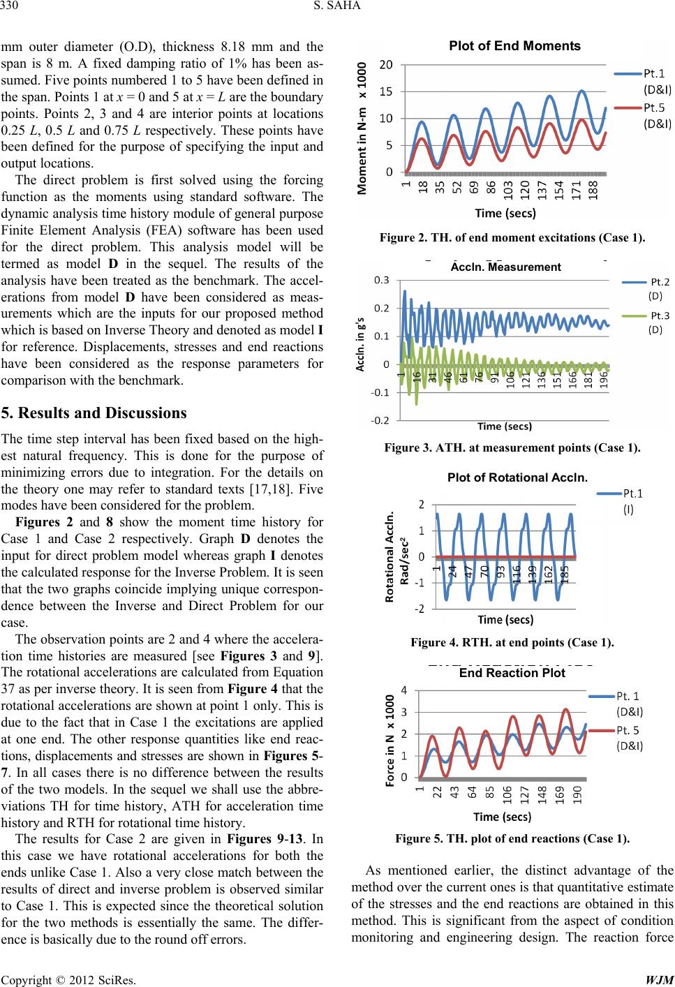 S. SAHA Copyright © 2012 SciRes. WJM 330 mm outer diameter (O.D), thickness 8.18 mm and the span is 8 m. A fixed damping ratio of 1% has been as- sumed. Five points numbered 1 to 5 have been defined in the span. Points 1 at x = 0 and 5 at x = L are the boundary points. Points 2, 3 and 4 are interior points at locations 0.25 L, 0.5 L and 0.75 L respectively. These points have been defined for the purpose of specifying the input and output locations. The direct problem is first solved using the forcing function as the moments using standard software. The dynamic analysis time history module of general purpose Finite Element Analysis (FEA) software has been used for the direct problem. This analysis model will be termed as model D in the sequel. The results of the analysis have been treated as the benchmark. The accel- erations from model D have been considered as meas- urements which are the inputs for our proposed method which is based on Inverse Theory and denoted as model I for reference. Displacements, stresses and end reactions have been considered as the response parameters for comparison with the benchmark. 5. Results and Discussions The time step interval has been fixed based on the high- est natural frequency. This is done for the purpose of minimizing errors due to integration. For the details on the theory one may refer to standard texts [17,18]. Five modes have been considered for the problem. Figures 2 and 8 show the moment time history for Case 1 and Case 2 respectively. Graph D denotes the input for direct problem model whereas graph I denotes the calculated response for the Inverse Problem. It is seen that the two graphs coincide implying unique correspon- dence between the Inverse and Direct Problem for our case. The observation points are 2 and 4 where the accelera- tion time histories are measured [see Figures 3 and 9]. The rotational accelerations are calculated from Equation 37 as per inverse theory. It is seen from Figure 4 that the rotational accelerations are shown at point 1 only. This is due to the fact that in Case 1 the excitations are applied at one end. The other response quantities like end reac- tions, displacements and stresses are shown in Figures 5- 7. In all cases there is no difference between the results of the two models. In the sequel we shall use the abbre- viations TH for time history, ATH for acceleration time history and RTH for rotational time history. The results for Case 2 are given in Figures 9-13. In this case we have rotational accelerations for both the ends unlike Case 1. Also a very close match between the results of direct and inverse problem is observed similar to Case 1. This is expected since the theoretical solution for the two methods is essentially the same. The differ- ence is basically due to the round off errors. Plot of End Moments Figure 2. TH. of end moment excitations (Case 1). A ccln. Measurement Figure 3. ATH. at measurement points (Case 1). Plot of Rotational Accln. 2 Figure 4. RTH. at end points (Case 1). End Reaction Plot Figure 5. TH. plot of end reactions (Case 1). As mentioned earlier, the distinct advantage of the method over the current ones is that quantitative estimate of the stresses and the end reactions are obtained in this method. This is significant from the aspect of condition monitoring and engineering design. The reaction force 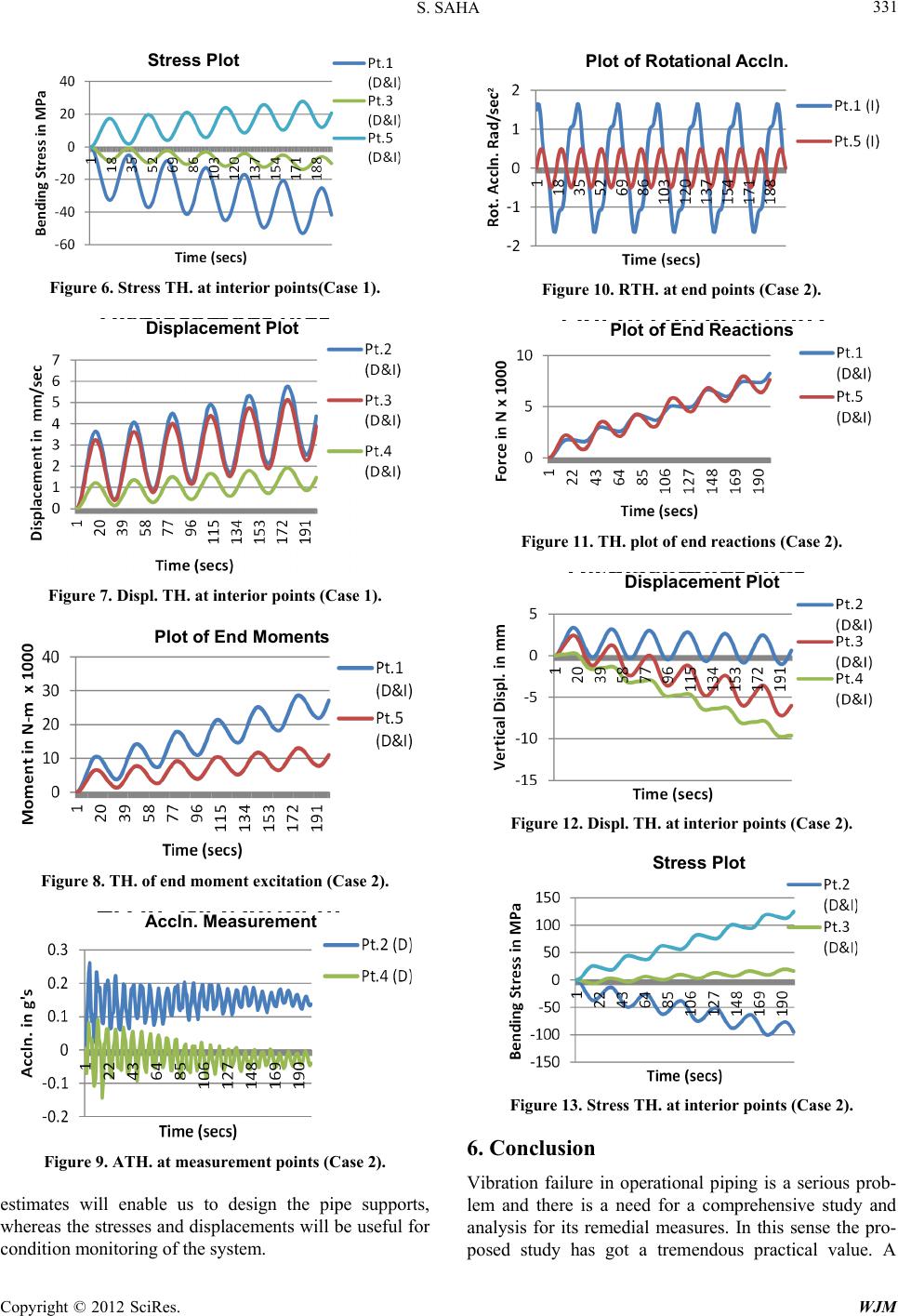 S. SAHA Copyright © 2012 SciRes. WJM 331 Stress Plot Figure 6. Stress TH. at interior points(Case 1). Displacement Plot Figure 7. Displ. TH. at interior points (Case 1). Plot of End Moments Figure 8. TH. of end moment excitation (Case 2). Accln. Measurement Figure 9. ATH. at measurement points (Case 2). estimates will enable us to design the pipe supports, whereas the stresses and displacements will be useful for condition monitoring of the system. Plot of Rotational Accln. 2 Figure 10. RTH. at end points (Case 2). Plot of End Reactions Figure 11. TH. plot of end reactions (Case 2). Displacement Plot Figure 12. Displ. TH. at interior points (Case 2). Stress Plot Figure 13. Stress TH. at interior points (Case 2). 6. Conclusion Vibration failure in operational piping is a serious prob- lem and there is a need for a comprehensive study and analysis for its remedial measures. In this sense the pro- posed study has got a tremendous practical value. A  S. SAHA Copyright © 2012 SciRes. WJM 332 quantitative method with proper mathematical basis has been provided in con trast to the cook book approach. By this method it is possible to quantify stresses, velocities and reaction forces. This gives us a basis for a proper engineering design. The method being simple can be easily adopted by engineers involved in trouble-shooting. Several improvements in the model are in line and planned for future work. These are like inclusion of lumped mass in the span or pipe bends. These will widen the range of application of the method and will be of greater practical use. REFERENCES [1] W. G. Garrison, “Major Fires and Explosions Analyzed for 30-Year Period,” Hydrocarbon Processing, Vol. 67, No. 9, 1988, pp. 115-122. [2] C. W. Groetsch, “Inverse Problems in Mathematical Sci- ences,” Vieweg Publishing, Wiesbaden, 1993. [3] V. Komornik and P. Loreti, “Fourier Series in Control Theory,” Springer Inc., New York, 2005. [4] D. D. Ang, R. Gorenflo, V. K. Le and D. D. Trong, “Mo- ment Theory and Some Inverse Problems in Heat Con- duction,” Springer Verlag, Hiedelberg, 2002. [5] S. Saha, “Estimation of Point Vibration Loads for Indus- trial Piping,” Journal of Pressure Vessel Technology, Vol. 131, No. 3, 2009, Article ID: 031205, 7 p. [6] W. A. Moussa and A. N. Abdel Hamid, “On the Evalua- tion of Dynamic Stresses in Pipelines Using Limited Vi- bration Measurements and FEA in the Time Domain,” Journal of Pressure Vessel Technology, Vol. 121, No. 1, 1999, pp. 241-245. doi:10.1115/1.2883665 [7] W. A. Moussa and A. N. Abdel Hamid, “On the Evalua- tion of Dynamic Stresses in Pipelines Using Limited Vi- bration Measurements and FEA in the Frequency Do- main,” Journal of Pressure Vessel Technology, Vol. 121, No. 1, 1999, pp. 37-41. [8] S. Saha, “A Technique for Estimation of Dynamic Stre- sses from Field Measurements for Operating Piping,” Proceedings for International Conference in Creep and Fatigue(CF-6), Kalpakkam, 22-25 January 2012, pp. 726- 733. [9] B. J. Dobson and E. Rider, “A Review of the Indirect Calculation of Excitation Forces from Measured Struc- tural Response Data,” Journal of Mechanical Engineering Science, Vol. 204, No. 2, 1990, pp. 69-75. [10] H. Goyder, “Method and Applications of Structural Mo- delling from Measured Structural Frequency Response Data,” Journal of Sound & Vibration, Vol. 68, No. 2, 1980, pp. 209-230. doi:10.1016/0022-460X(80)90466-6 [11] S. Nicaise and O. Zair, “Determination of Point Sources in Vibrating Beams by Boundary Measurements: Identi- fiability, Stability and Reconstruction Results,” Elec- tronic Journal of Differential Equations, Vol. 2004, No. 20, 2004, pp. 1-17. [12] G. Bruckner and M. Yamamoto, “Determination of Point Wave Sources by Point-Wise Observations: Stability and Reconstruction,” Inverse Problems, Vol. 16, No. 3, 2000, pp. 723-748. doi:10.1088/0266-5611/16/3/312 [13] M. Yamamoto, “Stability, Reconstruction Formula and Regularization for an Inverse Source Hyperbolic Problem by a Control Method,” Inverse Problems, Vol. 11, No. 2, 1995, pp. 481-496. doi:10.1088/0266-5611/11/2/013 [14] M. Yamamoto, “Determination of Forces in Vibrating Beams and Plates by Point-Wise and Line Observations by a Control Method,” Journal of Inverse and Ill-Posed Problems, Vol. 4, No. 5, pp. 437-457. [15] J. C. Wachel, “Piping Vi bration and Stress,” Proceedings of Machinery Vibration Monitoring & Analysis, Vibration Institute, New Orleans, 1981, pp. 1-20. [16] OM, “Code for Operation and Maintenance of Nuclear Power Plants,” ASME, New York, 2004. [17] L. Meirovitch, “Methods of Analytical Dynamics,” Dover Publications, New York, 2003. [18] R. R. Craig Jr., “Structural Dynamics,” John Wiley, Ho- boken, 1981. [19] E. Kreyszig, “Introductory Functional Analysis with App- lications,” John Wiley, Hoboken, 1978. [20] W. H. Press, S. A. Teukolsky, W. T. Vetterling and B. P. Flannery, “Numerical Recipes in C++,” Cambridge Uni- versity Press, Cambridge, 2002. [21] S. D. Downing and D. F. Socie, “Simple Rainflow Cou- nting Algorithms,” International Journal of Fatigue, Vol. 4, No. 1, 1982, pp. 31-40. 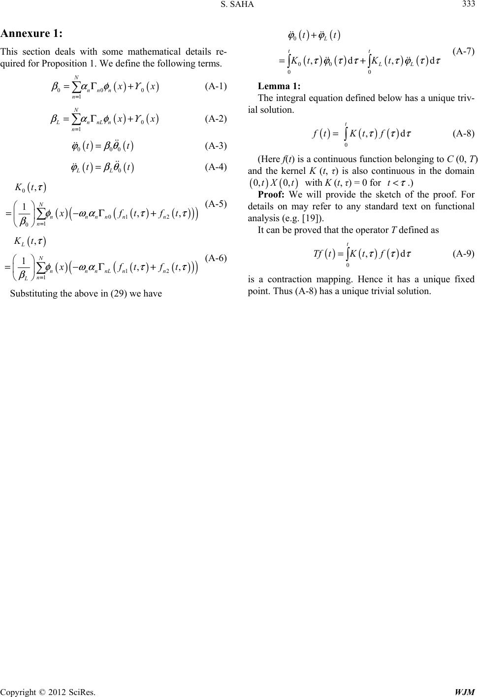 S. SAHA Copyright © 2012 SciRes. WJM 333 Annexure 1: This section deals with some mathematical details re- quired for Proposition 1. We define the following terms. () () 000 1 N nn n n x x βαφ = =Γ + Υ (A-1) ()() 0 1 N LnnLn n x x βαφ = =Γ + Υ (A-2) () () 000 tt ϕβθ = (A-3) () () 0LL tt ϕβθ = (A-4) () ()() () () () 0 01 2 1 0 , 1,, N nnnnn n n Kt xftft τ φ ωατ τ β = =−Γ+ (A-5) () ()() () () () 12 1 , 1,, L N nnnnLn n n L Kt xftft τ φ ωατ τ β = =−Γ+ (A-6) Substituting the above in (29) we have () () ()()()() 0 00 00 ,d ,d L tt LL tt Kt Kt ϕϕ τ ϕ ττ τ ϕ ττ + =+ (A-7) Lemma 1: The integral equation defined below has a unique triv- ial solution. ()()( ) 0 ,d t Ktfft τττ = (A-8) (Here f(t) is a continuous function belonging to C (0, T) and the kernel K (t, τ) is also continuous in the domain ()() 0, 0,tX t with K (t, τ) = 0 for t τ <.) Proof: We will provide the sketch of the proof. For details on may refer to any standard text on functional analysis (e.g. [19]). It can be proved that the operator T defined as ()()() 0 ,d t TftK tf τττ = (A-9) is a contraction mapping. Hence it has a unique fixed point. Thus (A-8) has a unique trivial solution. |